Table of Contents
Advertisement
Quick Links
Advertisement
Table of Contents

Related Manuals for Terasic CapSense CY8CMBR2016


Summary of Contents for Terasic CapSense CY8CMBR2016
-
Page 2: Table Of Contents
1.1 Features 1.2 About the KIT 1.3 Getting Help 1.4 Reference Documents 2.1 Layout and Components 2.2 Block Diagram 2.3 Kit Power 2.4 Default Switch and Jumper Settings 3.1 User Input/ Output 3.2 Host Communication Header 3.3 Sensor Module Header 3.4 Power Supply 4.1 LED Project Example 4.2 Jumper Configuration Example A... -
Page 3: Features
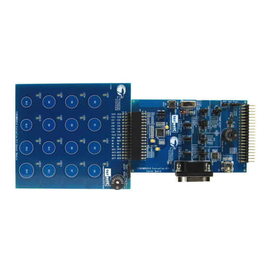
The kit contains 16 capacitive touch buttons organized in a matrix-style format appropriate for such as fire alarm control panels, security systems, and door locks. shows a photograph of the CapSense CY8CMBR2016 Evaluation kit. Figure 1-1... - Page 4 Key features of the evaluation kit include: 4x4 Matrix Solution o Simultaneous key press enabled o Mechanical matrix interface enabled for backwards compatibility Uses Cypress’s CY8CMBR2016-24LQXI CapSense Express controller SmartSense Auto-Tuning o Auto-tuning for PCB manufacturing variance o Adaptive Threshold Auto-tuning for different overlays o SNR Optimization to obtain robust performance Configurable o Pin configurable buttons...
-
Page 5: About The Kit
Portable Battery-Powered USB Charger (AA) Figure 1-2 shows the photograph of the Cypress CY8CMBR2016 EVK content. Figure 1-2 CY8CMBR2016 EVK Package Contents For support, please visit: CapSense Matrix Keypad Solution - From Terasic Technologies CY8CMBR2016 CapSense Design Guide CY8CMBR2016 Datasheet... -
Page 6: Layout And Components
This chapter covers the architecture of the kit including information on the components, how to power the kit, and default settings. Figure 2-1 indicates the locations of the connectors and key components. Figure 2-1 CY8CMBR2016 EVK with Component Diagram... -
Page 7: Block Diagram
Figure 2-2 shows the block diagram. Figure 2-2 Block Diagram of CY8CMBR2016 EVK... -
Page 8: Kit Power
The CY8CMBR2016 EVK comes with a preloaded factory configuration to demonstrate the features of the kit. The factory configurations allow you to quickly ensure that the kit is working properly. To power-up the board: 1. Connect the Sensor Module to the sensor module header (J20) of the Center Board. 2. -
Page 9: Default Switch And Jumper Settings
Figure 2-3 Jumper locations Table 2-1 describes the default jumper settings on the CY8CMBR2016 EVK and its description. Table 2-1 Default Jumper Setting and Description of Center Board Jumper Default Setting Description Buzz Select Select buzzer of Center Board or buzzer of Sensor (J2) Module. - Page 10 Configure the Scan Rate between High, Medium, Low, and Continuous. This jumper configures the Scan Rate rate at which the sensors are scanned – the higher (J4,J5,J6) the rate, faster the response and higher the power consumption. Configure the Sensitivity between High, Medium, Sensitivity and Low.
- Page 11 Power Select Select the power source from VCC5_HOST or VADJ_HOST or VCC3P3_HOST or VCC5_USB. (J21,J22,J23) Table 2-2 Default Jumper Setting and Description of Sensor Module Jumper Default Setting Description Enable/disable the buzzer of Sensor Module. Buzz ON/OFF (J2) Enable/disable the 16 LEDs of Sensor Module. ON/OFF (J3)
-
Page 12: User Input/ Output
This chapter provides detailed information on how to use the CY8CMBR2016 Evaluation kit. The user input/ output provides a versatile and reliable drop-in replacement for mechanical matrix buttons using an output truth table. The pins are connected to LEDs for demonstration purposes, the LED feature is not available in the CY8CMBR2016 device. - Page 13 Mechanical Matrix Truth Table Output The truth table for the 4x4 matrix solution is shown below. The dots indicate LED terminal connections between rows and columns. The button locations are shown in Figure 3-2. GPO_0 through GPO_3 share connections with LED-COL1 through LED-COL4, and GPO_4 through GPO_7 share connections with LED-ROW1 through LED-ROW4.
- Page 14 Figure 3-2 Button Location Reset Push-Button The CY8CMBR2016 EVK includes a reset push-button (SW1) to provide a system reset signal for designs loaded into the PSoC device. The push-button provides a high-logic level when it is pressed. Audio Beep Buzzer The CY8CMBR2016 EVK contains two audio beep buzzers.
- Page 15 4x4 Capacitive Button Matrix 16 CapSense buttons are laid out in a 4x4 matrix on the Sensor Module as shown in Figure 3-3. 12 are standard buttons marked with 0-9, *, and #. The remaining four buttons are unlabeled. Figure 3-3 CapSense Button Layout...
-
Page 16: Host Communication Header
The host communication header allows a host to control the kit. The header includes eight GPO interface pins for host communication plus one INT pin for generating an interrupt for the host controller. BUZZ_CENTER, SLEEP, and DEBUG signals are also on the header. Because this header shares a pin connection with the LED interface only one can be used. -
Page 17: Sensor Module Header
You can connect your own sensor module to the Center Board with the sensor module header. Power is provided through the USB Type mini-AB connector (5V) or from a host board through the host communication header (5V, 3.3V, or VADJ). The Power Selection jumper must match the power source you are using with the kit. -
Page 18: Led Project Example
This chapter introduces example projects and firmware features of the CY8CMBR2016 EVK. The first project example demonstrates how a PSoC device can integrate CapSense touch sensing and visual feedback. The CapSense buttons are configured so that when a button is touched the corresponding LED turns on. -
Page 19: Jumper Configuration Example B
Select Configure the Output Select to Factory LED (J14,J15,J16) Sensitivity Configure the Sensitivity to High (0.2pF) (J7,J8) Debug (J17) Disable the debug data out through the RS232 port Table 4-2 gives the jumper configuration for Project Example B Table 4-2 Jumper Configuration for Example B Jumper Default Setting Description... -
Page 20: Firmware Functionality
Select Configure the Output Select to Factory LED (J14,J15,J16) Sensitivity Configure the Sensitivity to Low (0.4pF) (J7,J8) Enable the debug data out through the RS232 port, Debug (J17) to use the UART port to see the debug data in Multi Chart Tool. The kit CD will include this tool. The LED project example firmware includes the following functions: SmartSense Auto-Tuning SmartSense Auto-Tuning automatically compensates for PCB variations, device process variations,... - Page 21 Scan Rate The firmware reads the resistor value on the Scan Rate pin and sets the scan rate of the CapSense device. The four possible scan rate configurations are: 1. Pin grounded – low 2. 1.5 K: (5%) to ground – medium 3.
-
Page 22: 4.5 Demonstration Setup
4.5 Demonstration Setup 1. Power on the board using an USB A to Mini-B cable. 2. Experiment with the project examples and features by adjusting the jumper settings. Note: Be careful not touch any connector or header pins during CapSense operation. It may add capacitance to the sensor lines and cause false triggering of the buttons. -
Page 23: Revision History
Version Change Log V1.0 Initial Version (Preliminary) Copyright © 2011 Terasic Technologies. All rights reserved. - Page 24 Mouser Electronics Authorized Distributor Click to View Pricing, Inventory, Delivery & Lifecycle Information: Terasic P0100...
Need help?
Do you have a question about the CapSense CY8CMBR2016 and is the answer not in the manual?
Questions and answers