
Related Manuals for TMG TMG-ST2031V


Summary of Contents for TMG TMG-ST2031V
- Page 1 ▶ W W W . T M G I N D U S T R I A L . C O M P 0 / 2 2 T o l l F r e e : 1 - 8 7 7 - 7 6 1 - 2 8 1 9...
-
Page 2: Main Specifications
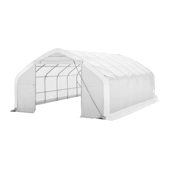
Main Specifications : Overall assembled size : W6 x L9 x H3.65 (m) / 19.68 x 29.52 x 11.97 (ft) Shoulder height : 2 (m) / 6.56 (ft) Front roll up door : 3 x 3 (m) / W9.84 x H9.84 (ft) Prior to assembly Please read the instructions carefully before installation. - Page 3 Keep the building surroundings clear at all times. TMG-ST2031V Part List Parts Graphical Description length code φ48xL1820mm Peak arch tube Upper rafter tube φ48xL1934mm (middle truss) Upper rafter tube φ48xL1934mm (front truss) Shoulder tube φ48xL1123mm (middle truss) Shoulder tube φ48xL1123mm (front and rear truss) φ48x1480mm...
- Page 4 Middle truss baseplate W200xL200mm Ratchet Door frame lower tube φ48xL1980mm (front and rear truss) Door frame upper tube φ48xL1405mm (front and rear truss) φ48xL1268mm Rear frame middle tube Door frame horizontal φ42xL1446mm tube (front and rear truss) Door frame horizontal φ42xL1450mm tube (rear truss) φ42xL1949mm...
- Page 5 Hex Bolt M10x70mm Hex Bolt M8x80mm Hex Bolt M10x30mm Hex Bolt M10x50mm φ8xL12m Nylon rope φ32mm Water plug Top cover Front cover panel Rear cover panel φ8xL180m Braided rope 1 bundle Ratchet straps W38xL800mm Scratch resistant tape ▶ W W W . T M G I N D U S T R I A L . C O M P 4 / 2 2 T o l l F r e e : 1 - 8 7 7 - 7 6 1 - 2 8 1 9...
- Page 6 Step 1 : Base plates installation. Installation diagram of expansion bolt. Part Part ▶ W W W . T M G I N D U S T R I A L . C O M P 5 / 2 2 T o l l F r e e : 1 - 8 7 7 - 7 6 1 - 2 8 1 9...
- Page 7 Step 2 : Install front truss. Part Part ▶ W W W . T M G I N D U S T R I A L . C O M P 6 / 2 2 T o l l F r e e : 1 - 8 7 7 - 7 6 1 - 2 8 1 9...
- Page 8 Step 3 : Install rear truss. Part Part ▶ W W W . T M G I N D U S T R I A L . C O M P 7 / 2 2 T o l l F r e e : 1 - 8 7 7 - 7 6 1 - 2 8 1 9...
- Page 9 Step 4 : Install the intermediate truss. Part Part ▶ W W W . T M G I N D U S T R I A L . C O M P 8 / 2 2 T o l l F r e e : 1 - 8 7 7 - 7 6 1 - 2 8 1 9...
- Page 10 Step 5 : Wrap (#26) around the sharp points of the joint to avoid friction between the fabric and the interface. Part ▶ W W W . T M G I N D U S T R I A L . C O M P 9 / 2 2 T o l l F r e e : 1 - 8 7 7 - 7 6 1 - 2 8 1 9...
- Page 11 Step 6 : Put up the front and rear truss and the intermediate truss. Part ▶ W W W . T M G I N D U S T R I A L . C O M P 1 0 / 2 2 T o l l F r e e : 1 - 8 7 7 - 7 6 1 - 2 8 1 9...
- Page 12 Step 7 : Install (#5) roof purlin. Part Part ▶ W W W . T M G I N D U S T R I A L . C O M P 1 1 / 2 2 T o l l F r e e : 1 - 8 7 7 - 7 6 1 - 2 8 1 9...
- Page 13 Step 8 : Install the diagonal bracing bars (#13). Part ▶ W W W . T M G I N D U S T R I A L . C O M P 1 2 / 2 2 T o l l F r e e : 1 - 8 7 7 - 7 6 1 - 2 8 1 9...
- Page 14 Step 9 : Install the remaining parts on the front truss. Part Part ▶ W W W . T M G I N D U S T R I A L . C O M P 1 3 / 2 2 T o l l F r e e : 1 - 8 7 7 - 7 6 1 - 2 8 1 9...
- Page 15 Step 10 : Install the remaining parts on the rear truss. Part Part ▶ W W W . T M G I N D U S T R I A L . C O M P 1 4 / 2 2 T o l l F r e e : 1 - 8 7 7 - 7 6 1 - 2 8 1 9...
- Page 16 Step 11 : Install front cover panel, what you see in this picture is the inside. Lift up (#23) cover panels, starting from the center point of the frame (highest ridge point) ,use ropes (#24) Center point through the grommets to tie the panel to the truss firmly.
- Page 17 What you see in this photo is outside The rope coming out from pulley11B must go through the upper wheel of pully 11A, then pull both ropes together slowly and start to lift the door cover. Tie both ropes to the corner baseplate. Now the door cover is up. When you drop down the door cover, do not let go too quick, otherwise it might get stuck and damage the fabric.
- Page 18 Step 12 : Install rear cover panel. Lift up (#23A) cover panels, starting from the center point of the frame (highest ridge point) ,use ropes (#24) Center point through the grommets to tie the panel to the truss firmly. Then continue from the middle to the sides to tie the panels to the arch pipe.
- Page 19 Step 13 : Install the top cover (#22) stretch and tighten top cover. Do not install the cover during windy weather! Stretch and adjust the cover from back and forth, to make sure it is square and centered. Unpack the top cover and place it along one of the long sides of the structure.
- Page 20 Part Part ▶ W W W . T M G I N D U S T R I A L . C O M P 1 9 / 2 2 T o l l F r e e : 1 - 8 7 7 - 7 6 1 - 2 8 1 9...
- Page 21 Step 14 : Tension the cover on the structure from both sides. Insert tension tubes (#14) slowly into the bottom groove pocket on both long sides. Add the water plug (#21) on the first tension tube to avoid tearing the fabric and add one to the end of last tube as well.
- Page 22 Step 15 : Install ratchet straps. Stretch and adjust the cover from left and right, to make sure it is square and centered. Cut the groove pocket where it aligns with ratchet (#7A), and use strap (#25) to pull tension tube (#14) toward the ratchet and tie it firmly there.
- Page 23 After the Installation Walk around and inspect the shelter periodically to make sure all components are still firmly secured and the whole shelter is well supported. Check all bolts and nuts as well as all connection points to make sure they are all in good position. Check the base plates, adjust the ropes and tie downs if required and clean the cover regularly.
Need help?
Do you have a question about the TMG-ST2031V and is the answer not in the manual?
Questions and answers