Advertisement
Quick Links
Advertisement

Related Manuals for TMG TMG-ST2041CV


Summary of Contents for TMG TMG-ST2041CV
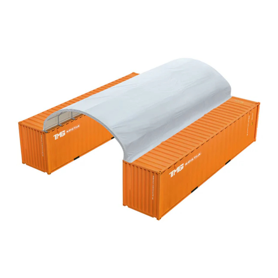
- Page 1 20' X 40' SINGLE TRUSS STORAGE CONTAINER SHELTER Main Specifications :...
-
Page 2: Main Specifications
Main Specifications : Overall assembled size : W6 x L12 x H2 (m) / 19.6 x 39.37 x 6.5(ft) Ridge Peak Height : 2 m / 6.5ft + container height Prior to assembly Please read the instructions carefully before installation. It is very important to follow your local safety regulations and industry standards during installation. - Page 3 TMG-ST2041CV Part List Parts Graphical Description length code φ48xL2192mm Dome arch pipe φ48xL1481mm Middle rafter tube φ48xL1428mm Shoulder tube Roof purlin φ42xL1148mm (horizontal tube) Middle truss connectors W50xL170mm Front and rear connectors W50xL111mm Middle truss baseplate W150xL200mm Left corner baseplate...
- Page 4 φ8x60m Braided rope 1 bundle Scratch resistant tape Half round head bolt M10x80mm Hex bolt M10x70mm φ32mm Water plug Self tapping screw #12x25mm ▶ W W W . T M G I N D U S T R I A L . C O M P 3 / 1 2 T o l l F r e e : 1 - 8 7 7 - 7 6 1 - 2 8 1 9...
- Page 5 Step 1 : Baseplate positioning and installation. Parts Graphical code ▶ W W W . T M G I N D U S T R I A L . C O M P 4 / 1 2 T o l l F r e e : 1 - 8 7 7 - 7 6 1 - 2 8 1 9...
- Page 6 Step 2 : Install 11 sets of trusses. Parts Graphical code 1x11 2x11 2x11 8x11 ▶ W W W . T M G I N D U S T R I A L . C O M P 5 / 1 2 T o l l F r e e : 1 - 8 7 7 - 7 6 1 - 2 8 1 9...
- Page 7 Step 3 : Wrap (#15) around the sharp points of the joint to avoid friction between the fabric and the interface. Parts Graphical code ▶ W W W . T M G I N D U S T R I A L . C O M P 6 / 1 2 T o l l F r e e : 1 - 8 7 7 - 7 6 1 - 2 8 1 9...
- Page 8 Step 4 : Put up all trusses. Parts Graphical code ▶ W W W . T M G I N D U S T R I A L . C O M P 7 / 1 2 T o l l F r e e : 1 - 8 7 7 - 7 6 1 - 2 8 1 9...
- Page 9 Step 5 : Installation of roof purlin. Parts Graphical code ▶ W W W . T M G I N D U S T R I A L . C O M P 8 / 1 2 T o l l F r e e : 1 - 8 7 7 - 7 6 1 - 2 8 1 9...
- Page 10 Step 6 : Install the cover. Parts Graphical code ▶ W W W . T M G I N D U S T R I A L . C O M P 9 / 1 2 T o l l F r e e : 1 - 8 7 7 - 7 6 1 - 2 8 1 9...
- Page 11 Step 7 : Install metal pipes on both sides. Parts Graphical code ▶ W W W . T M G I N D U S T R I A L . C O M P 1 0 / 1 2 T o l l F r e e : 1 - 8 7 7 - 7 6 1 - 2 8 1 9...
- Page 12 Step 8 : Tension the top cloth with tensioning device and braided rope. Parts Graphical code 1 bundle ▶ W W W . T M G I N D U S T R I A L . C O M P 1 1 / 1 2 T o l l F r e e : 1 - 8 7 7 - 7 6 1 - 2 8 1 9...
-
Page 13: After Installation
After Installation Walk around and inspect the building periodically to make sure the parts are firmly fixed and the whole building is well supported. Check all bolts and hardware connectors to make sure they are in place and tightened. Check the base plates, adjust the ropes if necessary and clean the cover regularly.
Need help?
Do you have a question about the TMG-ST2041CV and is the answer not in the manual?
Questions and answers