
Related Manuals for TMG TMG-ST2040C-1.0


Summary of Contents for TMG TMG-ST2040C-1.0
- Page 1 W W W . T M G I N D U S T R I A L . C O M P 0 / 9 T o l l F r e e : 1 - 8 7 7 - 7 6 1 - 2 8 1 9...
-
Page 2: Main Specifications
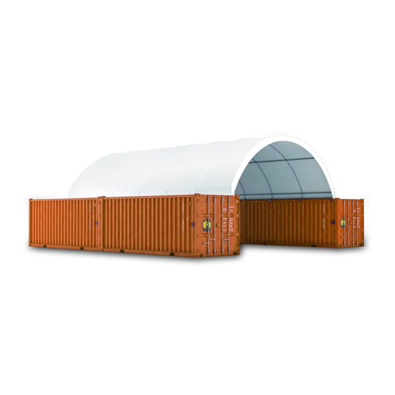
Main Specifications : Overall assembled size : W6 x L12 x H2 (m) / 20 x 40 x 6.5 (ft) Width : 6 m / 20ft Length : 12 m / 40 ft Ridge Peak Height : 2 m / 6.5 ft ... -
Page 3: Installation Steps
Be aware of the surrounding area. Do not set up the building near snowdrifts, open flames or exposed electrical wires. Do not keep heat sources near the fabric cover. Keep the building surroundings clear at all times. TMG-ST2040C-1.0 Part List Picture Description... - Page 4 Top cover tension tube Ratchets Tie down straps Hex bolt M10x70mm Locking bolt M10x80mm Top cover Water plug Braided rope Scratch resistant tape Step 2 : Place the containers making sure they are parallel and the correct width apart. Make sure there is a gap of about 3 feet around the building. the center point of the round pipe of the base is the reference point, and the diagonal X and Y must be equal.
- Page 5 Picture 1 Step 3 : Connect all trusses Layout all truss components on the ground in the correct configuration before bolting them together. Components are : (1x9) Peak arch tube (#1) (2x9) Middle rafter tube (#2) (2x9) Shoulder tube (#3) ...
- Page 6 There are total 9 trusses to build, use the hex bolt (#10) to connect all tubes together, wrap (#15) around truss joints (refer picture 2 as below) Picture 2 Step 4 : Put up all trusses Install each truss on the base tube.Use hex bolt (#10) to secure the truss to the truss baseplate.
- Page 7 Picture 3 Install purlin tubes (#4) and use locking bolts (#11) (refer picture 4 as below). Components are : (40) Purlin tube (#4) (45) Locking bolt (#11) Picture 4 Step 5 : Install the Ratchets. Install the ratchets on the bottom plates on both sides. (refer Picture 5 as below). Components are : (18)Ratchets (#8) ...
- Page 8 Picture 5 Overall structural inspection : check all components and trusses to ensure the entire structure is rectangular as specified in (picture 1). All trusses must be 90 degrees straight up from the container. Secure and tighten all bolts and nuts on this step. But do not over tie! Otherwise you might damage the tubes or components.
- Page 9 Components are : (12) Top cover tension tube A (#6) (2) Top cover tension tube B (#7) (18) Tie down straps (#9) (1) Top cover (#12) (4) Water plug (#13) (1) Braided rope (#14) Picture 6 W W W .
-
Page 10: After Installation
Picture 7 After Installation Walk around and inspect the building periodically to make sure the parts are firmly fixed and the whole building is well supported. Check all bolts and hardware connectors to make sure they are in place and tightened. Check the base plates, adjust the ropes if necessary and clean the cover regularly.
Need help?
Do you have a question about the TMG-ST2040C-1.0 and is the answer not in the manual?
Questions and answers