Assa Abloy SARGENT 80 Series Installation Instructions
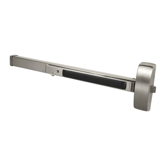
Exit device
Hide thumbs
Also See for SARGENT 80 Series:
- Installation instructions manual (40 pages) ,
- Installation instructions manual (44 pages)
Advertisement
Quick Links
Installation Instructions
80 Series Exit Device
57-Prefix Delayed Action
A. Mounting Instructions*
Use connectors allowed by
local code. Allow sufficient lead
length for removal of insert.
1. Mount exit device per instruction sheet provided.
2. Provide a 3/8" dia. min. raceway to allow insertion of electrical wires running between delayed action circuit board
and electrical hinge.
3. Wiring instructions (See wiring diagram for necessary info).
B. Operating Instructions
1. Delayed Egress (Start-up): Rotate key fully clockwise to initiate delayed egress mode. Reverse rotation of key to
remove it from cylinder. After approximately 5 seconds, the exit device will reset to the delayed egress mode. The
green indicator will illuminate. The auxiliary lock (electro-magnet) will become energized, and the exit device will
become armed. An attempt to egress by depressing the panic bar will initiate an irreversible process where an alarm
will sound intermittently, and the red indicator will flash. The auxiliary lock will stay energized for 15 seconds in
conformance with NFPA 101. In 15 seconds, the green indicator will extinguish, the red indicator will illuminate, and
the auxiliary lock will de-energize, allowing egress as in conventional panic bolt exit. This condition will continue
until it is reset by rotating the key clockwise to reset or initiate the delayed egress mode.
2. Maintained Egress Mode: Rotate key fully counterclockwise to initiate maintained egress mode. Reverse rotation of
key to remove it from cylinder. The red indicator will illuminate. The auxiliary lock (electro-magnet) will de-energize
indefinitely, and the exit device will function normally without triggering an alarm or requiring a delay period.
WARNING
This product can expose you to lead
which is known to the state of California
to cause cancer and birth defects or other
reproductive harm. For more information go
to www.P65warnings.ca.gov.
1-800-727-5477 • www.sargentlock.com
Copyright © 2009, 2022 SARGENT Manufacturing Company. All rights reserved. Reproduction in
whole or in part without the express written permission of SARGENT Manufacturing Company is
prohibited.
Increase
Time Delay
Decrease
Time Delay
Truss Head Screw
3. Momentary Egress: Rotate key fully clockwise to initiate momentary egress.
Reverse rotation of key to remove it from cylinder. The red indicator will illuminate.
The auxiliary lock (electro-magnet) will de-energize for approximately 5 seconds
and allow immediate egress. The exit device will automatically reset to the delayed
egress mode where the green indicator will illuminate. The momentary time delay
is factory-preset at approximately 5 seconds and is field-adjustable between 0-30
seconds (See Note above).
Note: To adjust momentary time delay,
turn potentiometer on circuit board.
3/8" dia. Holes for
Routing Wires
*Rail
*No field rail cutoff allowed.
Exit device must be ordered
for specific door width.
A6810G 8/22
Advertisement

Related Manuals for Assa Abloy SARGENT 80 Series


Summary of Contents for Assa Abloy SARGENT 80 Series
- Page 1 Installation Instructions 80 Series Exit Device 57-Prefix Delayed Action Note: To adjust momentary time delay, Increase A. Mounting Instructions* Time Delay turn potentiometer on circuit board. Use connectors allowed by Decrease local code. Allow sufficient lead Time Delay length for removal of insert. *Rail 3/8"...
- Page 2 The ASSA ABLOY Group is the global leader in access solutions. Every day we help people feel safe, secure and experience a more open world. 57 PREFIX DELAYED ACTION 80 SERIES EXIT DEVICE WIRING DIAGRAM 1. Exit device, 80 Series 57 Prefix Delayed Action 5.
Need help?
Do you have a question about the SARGENT 80 Series and is the answer not in the manual?
Questions and answers
Hello has there ever been an issue with the 80 series exit device and cold weather? my customer Says they have issues first thing in the morning with the door not completely unlocking they say it “ticks” And the receptionist has to get up and open the door. Any help will be great.