Table of Contents
Advertisement
Quick Links
Advertisement
Table of Contents

Related Manuals for Texas Instruments TUSB8040AEVM


Summary of Contents for Texas Instruments TUSB8040AEVM
- Page 1 TUSB8040A Evaluation Module User's Guide Literature Number: SLLU163 May 2012...
-
Page 2: Table Of Contents
Configuration Switches ....................Hardwired Configurations ........................SMBUS Support ........................EVM Installation ........................ Troubleshooting ......................Appendix A Schematics ................Appendix B TUSB8040AEVM Bill of Materials Table of Contents SLLU163 – May 2012 Submit Documentation Feedback Copyright © 2012, Texas Instruments Incorporated... -
Page 3: Introduction
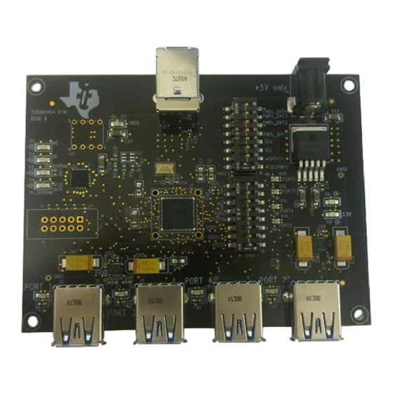
Note the EVM dimensions of 3” x 4” accommodates various lab test components, actual production implementations can be much smaller. Also, the TUSB8040AEVM is laid out to accept either a TUSB8040A unit or a socket. This socket functionality would not need to be duplicated on a production implementation. -
Page 4: Hardware Overview
3.0 jitter transfer function. USB Port Connectors The TUSB8040AEVM is equipped with 5 standard nine pin USB 3.0 port connectors. One of these five connectors, J1, is a Type B connector designed to interface with an upstream USB host or hub. The remaining connectors, J2-J5, are Type A connectors for connection to downstream devices or hubs. -
Page 5: Usb Port Connector - Noise Filtering
5 A because the hub must be able to source significant power on its downstream ports (900 mA per port). The TUSB8040AEVM uses a single channel LDO voltage regulator to drop 5 V to 3.3 V. The TPS7A4533, U20, is a 1.5-A output linear regulator (SLVS720). The 1.1-V core voltage required by the TUSB8040A is sourced by the 3.3-V rail to reduce unnecessary heat dissipation. -
Page 6: Optional Circuitry
ESD events are a concern, especially if the end equipment requirements exceed the device specifications (i.e. HBM 2000 kV, CDM 500 V) (SLVSAC2). The switches present on the TUSB8040AEVM are intended for TI lab evaluation only and are not required for production designs. -
Page 7: Hardware Set Up
Hardware Set Up Configuration Switches The TI TUSB8040AEVM has two sets of switches to facilitate configuration changes. Changing these switch settings without a complete understanding of the result is not recommended. Configuration inputs are only read by the TUSB8040A during power on reset, changing the switch settings while the EVM is powered on will have no effect. - Page 8 Port 3 are reported as removable by default. If the switch is set to the ON position, the terminal is pulled low and the TUSB8040A will report a device connected to Port 3 as non-removable. Hardware Set Up SLLU163 – May 2012 Submit Documentation Feedback Copyright © 2012, Texas Instruments Incorporated...
-
Page 9: Hardwired Configurations
Hardwired Configurations PORTINDz - The TUSB8040A has an internal pull up on this terminal, so port indicator LED support is not reported to the USB host by default. Since the TUSB8040AEVM has port indicator LEDs, this terminal has been pulled low. -
Page 10: Troubleshooting
If installed, remove the serial EEPROM from the EEPROM socket. The EVM does not require an EEPROM to operate. • In the case where a 12-V power supply has been attached to the EVM, the fault is non-recoverable. Hardware Set Up SLLU163 – May 2012 Submit Documentation Feedback Copyright © 2012, Texas Instruments Incorporated... -
Page 11: Appendix A Schematics
Appendix A Schematics The following pages contain schematics for the TUSB8040A. SLLU163 – May 2012 Schematics Submit Documentation Feedback Copyright © 2012, Texas Instruments Incorporated... - Page 12 0.001uF 0.01uF 0.1uF 0.001uF 0.01uF 0.1uF 0.001uF 0.01uF 0.1uF 0.001uF 0.01uF 0.1uF 10uF 0.001uF 0.01uF 0.1uF SIZE DWG NO: SCALE: NONE Thursday, January 19, 2012 Sheet Schematics SLLU163 – May 2012 Submit Documentation Feedback Copyright © 2012, Texas Instruments Incorporated...
- Page 13 TPD2EUSB30_NOPOP TPD2EUSB30_NOPOP USB_DM_DN1 USB_DM_DN3 USB_DP_DN1 USB_DP_DN3 TPD2EUSB30_NOPOP Optional ESD Protection Optional ESD Protection USB3 CONNECTORS TPD2EUSB30_NOPOP SIZE DWG NO: SCALE: NONE Thursday, January 19, 2012 Sheet SLLU163 – May 2012 Schematics Submit Documentation Feedback Copyright © 2012, Texas Instruments Incorporated...
- Page 14 FB2. If a ferrite bead with very low DC resistance is used, R82 should be populated with a 1.87K resistor. 1P1V_PG PAGE1 1P1V_PG POWER SIZE DWG NO: SCALE: NONE Thursday, January 19, 2012 Sheet Schematics SLLU163 – May 2012 Submit Documentation Feedback Copyright © 2012, Texas Instruments Incorporated...
-
Page 15: Appendix B Tusb8040Aevm Bill Of Materials
Appendix B TUSB8040AEVM Bill of Materials The following pages contain the BOM for TUSB8040AEVM. SLLU163 – May 2012 TUSB8040AEVM Bill of Materials Submit Documentation Feedback Copyright © 2012, Texas Instruments Incorporated... - Page 16 Vishay / Dale CRCW040237K4FKED 1.87K Vishay / Dale CRCW04021K87FKED 1.87K Vishay / Dale CRCW04024K99FKED TUSB8040A - USB 3.0 Hub Texas Instruments TUSB8040A 100QFN TUSB8040AEVM Bill of Materials SLLU163 – May 2012 Submit Documentation Feedback Copyright © 2012, Texas Instruments Incorporated...
- Page 17 Appendix B www.ti.com Table 1. TUSB8040AEVM BOM (continued) Item Quantity Reference Part Manufacturer Part Number Package TPS3808G33DBV - Voltage Supervisor Texas Instruments TPS3808G33DBV 6DBV AT24C04A-10PU-1.8 / AT24C04 / SOCKET - I2C EEPROM Atmel / Tyco 8DIP / 8SOIC SOCKET 2-641260-1...
- Page 18 TUSB8040AEVM Bill of Materials SLLU163 – May 2012 Submit Documentation Feedback...
- Page 19 Any exceptions to this are strictly prohibited and unauthorized by Texas Instruments unless user has obtained appropriate experimental/development licenses from local regulatory authorities, which is responsibility of user including its acceptable authorization.
- Page 20 FCC Interference Statement for Class B EVM devices This equipment has been tested and found to comply with the limits for a Class B digital device, pursuant to part 15 of the FCC Rules. These limits are designed to provide reasonable protection against harmful interference in a residential installation. This equipment generates, uses and can radiate radio frequency energy and, if not installed and used in accordance with the instructions, may cause harmful interference to radio communications.
- Page 21 Also, please do not transfer this product, unless you give the same notice above to the transferee. Please note that if you could not follow the instructions above, you will be subject to penalties of Radio Law of Japan. Texas Instruments Japan Limited (address) 24-1, Nishi-Shinjuku 6 chome, Shinjuku-ku, Tokyo, Japan http://www.tij.co.jp...
- Page 22 FDA Class III or similar classification, then you must specifically notify TI of such intent and enter into a separate Assurance and Indemnity Agreement. Mailing Address: Texas Instruments, Post Office Box 655303, Dallas, Texas 75265 Copyright © 2012, Texas Instruments Incorporated...
- Page 23 Any exceptions to this are strictly prohibited and unauthorized by Texas Instruments unless user has obtained appropriate experimental/development licenses from local regulatory authorities, which is responsibility of user including its acceptable authorization.
- Page 24 FCC Interference Statement for Class B EVM devices This equipment has been tested and found to comply with the limits for a Class B digital device, pursuant to part 15 of the FCC Rules. These limits are designed to provide reasonable protection against harmful interference in a residential installation. This equipment generates, uses and can radiate radio frequency energy and, if not installed and used in accordance with the instructions, may cause harmful interference to radio communications.
- Page 25 Also, please do not transfer this product, unless you give the same notice above to the transferee. Please note that if you could not follow the instructions above, you will be subject to penalties of Radio Law of Japan. Texas Instruments Japan Limited (address) 24-1, Nishi-Shinjuku 6 chome, Shinjuku-ku, Tokyo, Japan http://www.tij.co.jp...
- Page 26 FDA Class III or similar classification, then you must specifically notify TI of such intent and enter into a separate Assurance and Indemnity Agreement. Mailing Address: Texas Instruments, Post Office Box 655303, Dallas, Texas 75265 Copyright © 2012, Texas Instruments Incorporated...
- Page 27 IMPORTANT NOTICE Texas Instruments Incorporated and its subsidiaries (TI) reserve the right to make corrections, enhancements, improvements and other changes to its semiconductor products and services per JESD46, latest issue, and to discontinue any product or service per JESD48, latest issue.
- Page 28 Mouser Electronics Authorized Distributor Click to View Pricing, Inventory, Delivery & Lifecycle Information: Texas Instruments TUSB8040AEVM...
Need help?
Do you have a question about the TUSB8040AEVM and is the answer not in the manual?
Questions and answers