
Related Manuals for Texas Instruments TUSB7340


Summary of Contents for Texas Instruments TUSB7340
- Page 1 TUSB7320/TUSB7340 EVM User's Guide User's Guide Literature Number: SLLU146B May 2011 – Revised August 2012...
-
Page 2: Table Of Contents
Contents ........................Introduction ......................... EVM Board ................TUSB7320 and TUSB7340 DEMO Boards ........................Hardware Setup ........................Headers ........................VBUS ....................PCI Express Slot Options ..........................Bringup ......................WAKE Testing Setup ........................SMI Support ........................Schematics ................TUSB7320 DEMO EVM REVB Schematics ................ - Page 3 List of Figures .................... TUSB7320 DEMO EVM REVB .................... TUSB7340 DEMO EVM REVB ..............SMI via Location for TUSB7340 DEMO EVM REVB List of Tables ..................TUSB7320 DEMO REVB BOM ..................TUSB7340 DEMO REVB BOM SLLU146B – May 2011 – Revised August 2012...
- Page 4 This guide is intended to describe the necessary information needed to operate either the TUSB7320 DEMO EVM REVB or TUSB7340 DEMO EVM REVB boards. In this document you will find how to setup and use the EVM boards. The schematics and bill of materials are also detailed at the end of the document.
-
Page 5: Introduction
SLLU146B – May 2011 – Revised August 2012 Introduction The TUSB7340 is a USB 3.0 xHCI 0.96 compliant host controller that supports up to four downstream ports. The TUSB7320 supports up to two downstream ports. The TUSB73x0 interfaces to the host system via a PCIe x1 Gen 2 interface and provides SuperSpeed, High-speed, Full-speed, or Low-speed connections on the downstream USB ports. -
Page 6: Evm Board
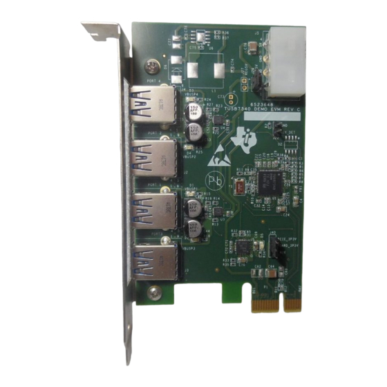
EVM Board TUSB7320 and TUSB7340 DEMO Boards The TUSB7320 and TUSB7340 DEMO boards are both PCI Express X1 Standard Height cards. The dimensions of both boards are 4.376 inches by 2.571 inches. The two figures below depict how the boards look. - Page 7 TUSB7320 and TUSB7340 DEMO Boards www.ti.com PORT4 PORT2 PORT1 PORT3 Figure 2. TUSB7340 DEMO EVM REVB SLLU146B – May 2011 – Revised August 2012 EVM Board Submit Documentation Feedback Copyright © 2011–2012, Texas Instruments Incorporated...
-
Page 8: Hardware Setup
AUX_DET will be high. If a jumper shunt is placed over J22, the AUX_DET will be low. The J26 header is used to route 5 V from the IDE Power Connector (J5) to the Texas Instruments TPS2560 USB power switch. This header should always have a Jumper Shunt populated. For more information on the Texas Instruments TPS2560, please visit www.ti.com. -
Page 9: Bringup
PC, then you can proceed step 8. Otherwise, you will need to install the xHCI driver by running the TI xHCI driver setup utility. 8. You can now insert devices into the USB ports. SLLU146B – May 2011 – Revised August 2012 Bringup Submit Documentation Feedback Copyright © 2011–2012, Texas Instruments Incorporated... -
Page 10: Wake Testing Setup
NOTE: For some motherboards, WAKE from a PCIe slot is not supported or is only supported on PCIE X1 slots. Please make sure to use a motherboard that supports WAKE from any PCIe slot. WAKE Testing Setup SLLU146B – May 2011 – Revised August 2012 Submit Documentation Feedback Copyright © 2011–2012, Texas Instruments Incorporated... -
Page 11: Smi Support
The SMI pin from the TUSB7320 is brought out to a header labeled SMI. This header is located to the left of J22. The SMI pin from the TUSB7340 is brought out to a via located on the bottom of board near U1. The via is located between C10 and C34 and just above C31. -
Page 12: Schematics
SLLU146B – May 2011 – Revised August 2012 Schematics The following pages contain schematics for the TUSB7320 and TUSB7340. Schematics SLLU146B – May 2011 – Revised August 2012 Submit Documentation Feedback Copyright © 2011–2012, Texas Instruments Incorporated... -
Page 13: Tusb7320 Demo Evm Revb Schematics
- PCIE_RXP/N within 5mils - PCIE_REFCLKP/N within 25mils. RX/TX PCIE CONNECTOR TUSB7320 DEMO REVB SIZE DWG NO: SCALE: NONE Sheet Tuesday, March 08, 2011 SLLU146B – May 2011 – Revised August 2012 Schematics Submit Documentation Feedback Copyright © 2011–2012, Texas Instruments Incorporated... - Page 14 0.1uF 0.1uF 0.1uF TUSB7320 0.01uF 0.1uF 0.1uF 0.01uF 0.1uF 0.1uF 0.01uF 0.1uF SIZE DWG NO: SCALE: NONE Tuesday, March 22, 2011 Sheet Schematics SLLU146B – May 2011 – Revised August 2012 Submit Documentation Feedback Copyright © 2011–2012, Texas Instruments Incorporated...
- Page 15 PCIE CEM SPEC MAX VALUES: USB3 AND PCIE CONNECTORS PCIE_3P3V: 3 AMPS. VAUX: 375mA SIZE DWG NO: SCALE: NONE Monday, March 21, 2011 Sheet SLLU146B – May 2011 – Revised August 2012 Schematics Submit Documentation Feedback Copyright © 2011–2012, Texas Instruments Incorporated...
- Page 16 NOTE: USE LOW ESR CAP VSENSE 22uF_NF TPS5450_NF 0.01uF_NF 3.16K_NF POWER SIZE DWG NO: NOTE: ONLY POPULATE ONE OPTION SCALE: NONE Tuesday, March 22, 2011 Sheet Schematics SLLU146B – May 2011 – Revised August 2012 Submit Documentation Feedback Copyright © 2011–2012, Texas Instruments Incorporated...
-
Page 17: Tusb7340 Demo Evm Revb Schematics
TUSB7340 DEMO EVM REVB Schematics www.ti.com TUSB7340 DEMO EVM REVB Schematics EPROM VIA AND TRACE REQUIREMENTS: - MIN VIA PAD SIZE 20mils - MIN spacing between trace and pad is 5mils DP/DM - MIN spacing between VIA and pad is 5mils... - Page 18 TUSB7340 DEMO EVM REVB Schematics www.ti.com BOARD_3P3V POPULATE R2 FOR WAKE SUPPORT. JUMPER J22 FOR NO WAKE SUPPORT 0402 HDR2X1 M .1 NOPOP 0402 BOARD_3P3V BOARD_3P3V BOARD_1P1V BOARD_3P3V VDDA3P3V BOARD_3P3V 0.1uF NOPOP NOPOP 0402 0402 NOPOP NOPOP NOPOP NOPOP 0402...
- Page 19 TUSB7340 DEMO EVM REVB Schematics www.ti.com BOARD_3P3V TDK_TCE_1210 USB_DM_DN1 pg2 BOARD_5V USB_DP_DN1 pg2 DS1_VBUS VBUS IND_USB_DM_DN1 DOWNSTREAM TPD2EUSB30_NF 0402 IND_USB_DP_DN1 0402 PORT1 USB_SSRXP_DN1 0.1uF USB_SSRXP_DN1 SSRXN USB_SSRXN_DN1 SSRXP USB_SSRXN_DN1 DS3_VBUS OUT1 IND_DS_TXP1 SSTXN OVERCUR3Z FAULT1Z SSTXP CAPDSTXP1 0.1uF PWRON3Z SHIELD0...
- Page 20 TUSB7340 DEMO EVM REVB Schematics www.ti.com 1.1V REGULATOR BOARD_1P1V BOARD_3P3V BOARD_3P3V 0402 OUTPUT 1.13K 4.53K 1.0V GRSTZ 1.37K 4.42K 1.05V 1.87K 4.99K 1.1V (DEFAULT) LED Green 0805 10uF 4.7K BIAS 0.1uF 0402 2.49K 4.99K 1.2V 1.87K EN1P1 0402 FB_1PT1V 22uF SS1P1 0.01uF...
-
Page 21: Appendix A Bill Of Materials
MH_125mil PCIe x1 Edge PCIe_X1 R1,R3,R4,R5,R6,R7, NOPOP R8,R9, R18,R20 R2,R13,R14,R31 9.09K R11,R32 4.7K R12,R17,R21 R15,R16,R34 30.9K 1.87K 4.99K 10K_NF 3.16K_NF SLLU146B – May 2011 – Revised August 2012 Bill of Materials Submit Documentation Feedback Copyright © 2011–2012, Texas Instruments Incorporated... - Page 22 Jump Shunt Tyco 881545-2 The below table is the bill of materials for the TUSB7340 DEMO EVM REVB board. The rows marked in yellow are components that are not populated on the EVM board. Table 2. TUSB7340 DEMO REVB BOM...
- Page 23 Appendix A www.ti.com Table 2. TUSB7340 DEMO REVB BOM (continued) Item Quantity Reference Part Footprint Tolerance Manufacturer Manufacturer PN 15µH_NF DR127 Coiltronics DR127-150-R L2,L4,L5,L7,L8,L10, TCE_1210_900_ TDK_TCE_1210 TDK_TCE_1210 L11, L13 2P_T MH1,MH2 PLATED_MH MH_125mil PCI Express x1 Edge PCIe_X1 R1,R3,R4,R5,R6,R7, NOPOP...
- Page 24 Any exceptions to this are strictly prohibited and unauthorized by Texas Instruments unless user has obtained appropriate experimental/development licenses from local regulatory authorities, which is responsibility of user including its acceptable authorization.
- Page 25 FCC Interference Statement for Class B EVM devices This equipment has been tested and found to comply with the limits for a Class B digital device, pursuant to part 15 of the FCC Rules. These limits are designed to provide reasonable protection against harmful interference in a residential installation. This equipment generates, uses and can radiate radio frequency energy and, if not installed and used in accordance with the instructions, may cause harmful interference to radio communications.
- Page 26 Also, please do not transfer this product, unless you give the same notice above to the transferee. Please note that if you could not follow the instructions above, you will be subject to penalties of Radio Law of Japan. Texas Instruments Japan Limited (address) 24-1, Nishi-Shinjuku 6 chome, Shinjuku-ku, Tokyo, Japan http://www.tij.co.jp...
- Page 27 FDA Class III or similar classification, then you must specifically notify TI of such intent and enter into a separate Assurance and Indemnity Agreement. Mailing Address: Texas Instruments, Post Office Box 655303, Dallas, Texas 75265 Copyright © 2012, Texas Instruments Incorporated...
- Page 28 IMPORTANT NOTICE Texas Instruments Incorporated and its subsidiaries (TI) reserve the right to make corrections, enhancements, improvements and other changes to its semiconductor products and services per JESD46C and to discontinue any product or service per JESD48B. Buyers should obtain the latest relevant information before placing orders and should verify that such information is current and complete. All semiconductor products (also referred to herein as “components”) are sold subject to TI’s terms and conditions of sale supplied at the time...
Need help?
Do you have a question about the TUSB7340 and is the answer not in the manual?
Questions and answers