Advertisement
Quick Links
OPERATION MANUAL
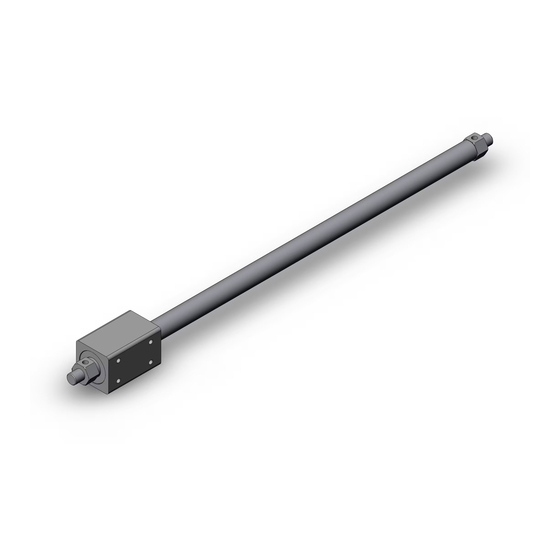
TITLE: Rodless Cylinder
○Read this manual thoroughly before mounting and
operation.
○Especially,carefully read the description concerning
safety.
○Keep this manual where accessible when necessary.
SMC CORPORATION
N o .
CY3B Series
C Y * B - O M 0 0 0 1 H - A
FORMAT No.FOM007-2
1 / 1 4
Advertisement

Related Manuals for SMC Networks CY3B Series


Summary of Contents for SMC Networks CY3B Series
- Page 1 N o . C Y * B - O M 0 0 0 1 H - A 1 / 1 4 OPERATION MANUAL TITLE: Rodless Cylinder CY3B Series ○Read this manual thoroughly before mounting and operation. ○Especially,carefully read the description concerning safety....
- Page 2 INDEX 1.Installation to Application 3 2.Actuating Force and Moment 9 3.Vertical Operation 10 4.Immediate Stop 11 5.Operating Air and Piping 12 6.Disassembly and Maintenance 12 7.Other Cautions for Operation 13 8.Made to Order 13 9.Internal Construction and Parts List 14...
-
Page 3: Safety Instructions
付表 3A Safety Instructions These safety instructions are intended to prevent hazardous situations and/or equipment damage. These instructions indicate the level of potential hazard with the labels of “Caution,” “Warning” or “Danger.” They are all important notes for safety and must be followed in addition to International Standards (ISO/IEC) , and other safety regulations. -
Page 4: Limited Warranty And Disclaimer/Compliance Requirements
付表 3A Safety Instructions Caution 1. The product is provided for use in manufacturing industries. The product herein described is basically provided for peaceful use in manufacturing industries. If considering using the product in other industries, consult SMC beforehand and exchange specifications or a contract if necessary. - Page 5 1.Installation to Application The rodless cylinder presented in this manual is not equipped with non-rotation device and allows external slider to rotate. Also, the rod less cylinder can’t resist direct large load and needs another axis (LM guide etc.) as a guide to support the load. 1-1) Installation of cylinder body Before installation of cylinder body, be sure to fix head covers at its both ends.
- Page 6 1-2) Installation of external slider and load Consider the following two points for mounting of external slider and load. Ⅰ-a) The cylinder is deflected by self-weight as shown on Fig. 2. This means longer stroke produces larger displacement of alignment. Fig.
- Page 7 Ⅰ-b) The misalignment between cylinder body and guide (orbit) may be caused depending on machining accuracy of the space for mounting. Therefore, the installation must be performed to compensate the misalignment. The following two show the example with or without concern about misalignment respectively.
- Page 8 Bearing Load base ide shaft Cylinder tube External slider Detail of A Wrong example Correct example View A Load base Load base External slider Spacer External slider Clearance Detail of B Detail of B By tightening of the bolt, the load base and Insert the spacer to keep flexibility in cylinder body cylinder body are in the state similar to direct and load base even after the bolt is tightened.
- Page 9 Wrong example Correct example Center of axis Guide shaft Cylinder body Guide by LM guide Bracket Load Load Since the cylinder is subject to direct moment The load is supported by guide shaft and the of load, guide shaft can work as only clearance is provided to compensate misalignment.
- Page 10 The misalignment can be checked by the following procedure. 1) After installation of cylinder to application, increase pressure of regulator gradually before checking operation of cylinder at operating pressure, and then calculate Adjust to minimize this increase min. pressure which enables smooth operation of cylinder over full stroke.
- Page 11 2.Actuating force and moment 2-1) Actuating force The actuating force of rodless cylinder is ideally equal to thrust at center of axis of piston but normally, as shown on Fig. 5-1, it is taken as FnN at the part away from the Recommended center by Lo cm.
-
Page 12: Vertical Operation
2-2) Moment at stroke end 3.Vertical Operation If the rodless cylinder is used for the load If the cylinder is operated in vertical direction, with large inertia, the following operating consider the same points as section 2. failures may be caused at stroke end. As shown on Fig. -
Page 13: Intermediate Stop
4.Intermediate Stop 4-1) Consider the following point to stop the load on the way of stroke by external stopper etc. a) Operating pressure Table 2 Operating pressure limit Keep operating pressure below the limit for intermediate stop shown on Table 2. The operation at higher pressure may cause thrust over holding Cylinder Operating... - Page 14 5.Operating Air and Piping 5-1) Install air filter. The rodless cylinder is non-lubrication type. Install air filter to upstream near the valve and adjust pneumatic pressure decreased to desired set pressure by regulator. 5-2) Lubrication to compressed air The rodless cylinder can be operated only by initial lubrication at shipment. But if the lubrication needs to be added due to specifications, use Turbin oil class 1 (no additive) ISO VG32.
- Page 15 7.Other Cautions for Operation 7-1) Some of internal components of cylinder is made of iron. Protect them from direct splash of water etc. If such a situation can’t be avoided, contact SMC separately. 7-2) Before piping, perform flashing inside the piping to prevent intrusion of dust and cutting chip inside the cylinder.
- Page 16 9.Internal Construction and Parts List...
- Page 17 Revision 4-14-1, Sotokanda, Chiyoda-ku, Tokyo 101-0021 JAPAN Tel: + 81 3 5207 8249 Fax: +81 3 5298 5362 http://www.smcworld.com Note: Specifications are subject to change without prior notice and any obligation on the part of the manufacturer. © 2011 SMC Corporation All Rights Reserved...
Need help?
Do you have a question about the CY3B Series and is the answer not in the manual?
Questions and answers