Table of Contents
Advertisement
Quick Links
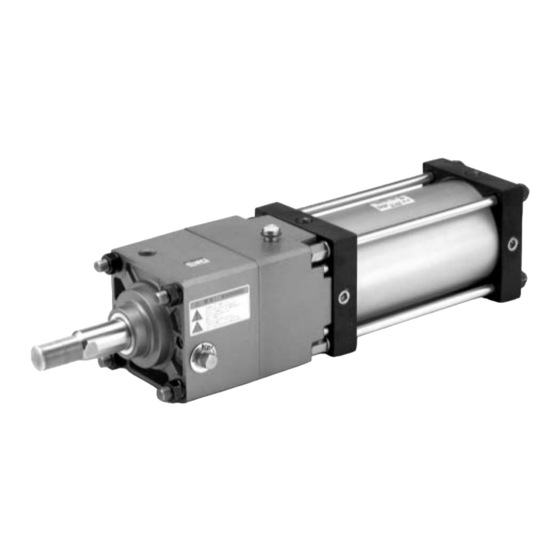
Cylinder with Lock
Double Acting, Single Rod
Series
ø125, ø140, ø160
CNS
Without
auto switch
CDNS
With auto switch
Built-in magnet
Mounting style
B
Basic style
L
Foot style
F
Rod side flange style
G
Head side flange style
∗ Auto switches are not
C
Single clevis style
D
Double clevis style
T
Center trunnion style
Bore size
125
125 mm
140
140 mm
160
160 mm
Built-in Magnet Cylinder Model
In the case of built-in magnet without auto
switch, the symbol for auto switch is "Nil".
(Example) CDNSL140-100
CNS
How to Order
L
125
125
L
Tubing material
Nil
Aluminum tube
∗
F
Steel tube
available
with
steel
tube.
Cylinder stroke (mm)
Refer to "Maximum Stroke"
100
D
100
D
Locking
direction
D
Both directions
With rod boot/cushion
Nil
With cushion in both ends
N
Without cushion
Cushion
R
With rod bumper
H
With head bumper
∗ In the case of one side, it is in the lock side.
∗∗ When the symbols are two or more, indicate
them alphabetically.
- X1166
- X1166
G Porting
Advertisement
Table of Contents

Related Manuals for SMC Networks CNS Series


Summary of Contents for SMC Networks CNS Series
- Page 1 Cylinder with Lock Double Acting, Single Rod Series ø125, ø140, ø160 How to Order - X1166 Without auto switch - X1166 CDNS With auto switch Built-in magnet Mounting style Basic style Tubing material G Porting Locking Foot style Aluminum tube direction Rod side flange style ∗...
- Page 2 Cylinder with Lock Series Double Acting, Single Rod Model Series Type Action Bore size (mm) Lock operation „ Double Non-lube 125, 140, 160 Spring locking acting „ CDNS Cylinder Specifications Type Non-lube Fluid Proof pressure 1.46 MPa Max. operating pressure 0.97 MPa Min.
- Page 3 Series Mounting Bracket Part No. Bore size (mm) Foot CS1-L12 CS1-L14 CS1-L16 Flange CS1-F12 CS1-F14 CS1-F16 Single clevis CS1-C12 CS1-C14 CS1-C16 Double clevis CS1-D12 CS1-D14 CS1-D16 Note 1) When ordering foot bracket, order 2 pieces per cylinder. Note 2) ø125 to ø160 rod side flange styles use Series CS1 long stroke flanges.
- Page 4 Series Dimensions Basic style (B): CNSB 2-MA Thread effective depth R Rc BQ plug with breathing hole BC element FA GB G BP 2-G P Width across flats Unlocking port Cylinder port S + Stroke ZZ + Stroke Bore size Stroke range (mm) (mm)
- Page 5 Cylinder with Lock Series Double Acting, Single Rod Foot style (L): CNSL Rc BQ plug with breathing hole 2-MA BC element Thread effective depth R Rc BP 2-Rc P (For NPT port) Unlocking port Cylinder port 4-øLD Width across flats S + Stroke LS + Stroke ZZ + Stroke...
- Page 6 Series Dimensions Rod side flange style (F): CNSF Rc BQ plug with breathing hole BC element Rc BP Width across GL GR 2-Rc P 4-øFD flats KA Unlocking port Cylinder port S + Stroke ZZ + Stroke Long stroke Rc BQ plug with breathing hole BC element Width across flats GL GR...
- Page 7 Cylinder with Lock Series Double Acting, Single Rod Head side flange style (G): CNSG 2-MA Rc BQ plug with breathing hole Thread effective BC element depth R G BP 2-G P 4-øFD Unlocking port Cylinder port Width across flats S + Stroke ZZ + Stroke Bore size Stroke range...
- Page 8 Series Dimensions Single clevis style (C): CNSC Rc BQ plug with breathing hole øCD hole H10 BC element Shaft d9 G BP 2-G P Unlocking port Width across flats Cylinder port S + Stroke Z + Stroke ZZ + Stroke 2-MA Thread effective depth R GR GL...
- Page 9 Cylinder with Lock Series Double Acting, Single Rod Double clevis style (D): CNSD øCD hole H10 Rc BQ plug with breathing hole (For NPT port) Shaft d9 BC element Rc BP 2-Rc P Width across flats Unlocking port Cylinder port S + Stroke Z + Stroke ZZ + Stroke...
- Page 11 Series Accessory Bracket Dimensions Y Type Double Knuckle Joint ∗ Pin and snap ring are shipped together with double clevis and double knuckle joint. Hole H10 øND Material: Cast iron Shaft d9 Applicable bore Part no. size (mm) Y-12 +0.084 +0.3 –0.1 M30 x 1.5...
- Page 12 Series Accessory Bracket Dimensions Single/Double Knuckle Joint Mounting Applicable knuckle joint part no. Symbol Bore Y type double knuckle I type single knuckle size (mm) Y-12 156.5 I-12 161.5 I-14 Y-14 170.5 I-16 Y-16 A, H Dimensions When Mounting a Single/Double Knuckle Joint together with a Rod End Nut Bore size (mm) ∗...
-
Page 13: Specific Product Precautions
Series Specific Product Precautions 1 Be sure to read before handling. Design of Equipment and Machinery Selection Warning Warning 1. Construct so that the human body will not come into 3. In order to further improve stopping accuracy, the direct contact with driven objects or the moving time from the stop signal to the operation of the parts of the cylinders with lock. - Page 14 Series Specific Product Precautions 2 Be sure to read before handling. Mounting Pneumatic Circuit Caution Warning 1. Precautions when using the base unit and when 1. Be certain to use an pneumatic circuit which will changing bracket positions, etc. apply balancing pressure to both sides of the piston The lock unit and cylinder rod cover are assembled as shown when in a locked stop.
-
Page 15: Pneumatic Circuit
Series Specific Product Precautions 3 Be sure to read before handling. Pneumatic Circuit Manually Unlocking Caution Warning 1. A 3 position pressure center solenoid valve and regulator with 1. Never operate the unlocking cam until safety has check valve can be replaced with two 3 port normally open been confirmed. -
Page 16: Maintenance
Series Specific Product Precautions 4 Be sure to read before handling. Maintenance Caution 3) Similarly, apply 0.3 MPa or more of compressed air to the 1. Lock units for Series CNS are replaceable. unlocking port of the new lock unit, and replace the new lock To order replacement lock units for Series CNS, use the unit’s temporary axis with the previous piston rod assembly. -
Page 17: Model Selection
Series Model Selection Step (1) Precautions on Model Selection Find the maximum load speed V. Find the maximum load speed: V (mm/s) from the load movement Caution time: t (s) and the movement distance: st (mm). 1. In order that the originally selected maximum speed is not exceeded, be certain to use a speed controller to adjust the total movement distance of the load so that movement takes Graph (1) - Page 18 Series Model Selection Selection Graph Graph (2) Graph (5) 0.3 MPa ≤ P < 0.4 MPa 0.3 MPa ≤ P < 0.4 MPa 3000 3000 2000 2000 1000 1000 ø160 ø140 ø125 ø160 ø140 ø125 Maximum speed: V (mm/s) Maximum speed: V (mm/s) Graph (3) Graph (6) 0.4 MPa ≤...
Need help?
Do you have a question about the CNS Series and is the answer not in the manual?
Questions and answers