Table of Contents
Advertisement
Quick Links
Advertisement
Table of Contents

Related Manuals for SMC Networks CS1 N125 Series


Summary of Contents for SMC Networks CS1 N125 Series
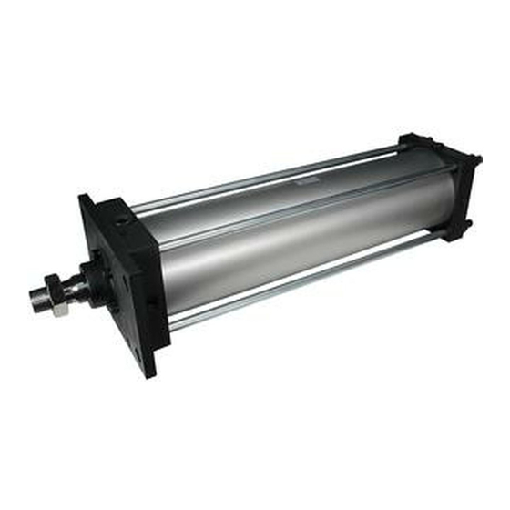
- Page 1 No: CS1*-OM0004F- PRODUCT NAME Air cylinder (Non-lube) MODEL/ Series CS1*N125~300...
-
Page 2: Table Of Contents
Contents 1. Safety instructions 2. Product specifications 1) Specifications 2) Maximum stroke 3) Maximum usable stroke due to lateral load 4) Relationship between cylinder size and maximum stroke by the mounting style 5) Theoretical output 6) Kinetic energy that can be absorbed by cushion mechanism 7) Class 2 pressure vessel 8) How to order 3. -
Page 3: Safety Instructions
Safety Instructions These safety instructions are intended to prevent hazardous situations and/or equipment damage. These instructions indicate the level of potential hazard with the labels of Caution Warning Danger " " " " " " They are all important notes for safety and must be followed in addition to International standards (ISO/IEC), Japan Industrial Standards (JIS) and other safety regulations *1) ISO 4414: Pneumatic fluid power - - General rules relating to systems. - Page 4 mechanical protective function, and periodical checks to confirm proper operation. - 3 -...
- Page 5 Caution 1. The product is provided for use in manufacturing industries. The product herein described is basically provided for peaceful use in manufacturing industries. If considering using the product in other industries, consult SMC beforehand and exchange specifications or a contract if necessary. If anything is unclear, contact your nearest sales branch.
- Page 6 Warning The compatibility of pneumatic equipment is the responsibility of the person who designs the pneumatic system or decides its specifications. Since the product shown here is used in various operating conditions, the pneumatic system designer or the person prescribing its specifications based on necessary analysis and tests should determine its suitability to a system.
-
Page 7: Product Specifications
2. Product Specifications F 1) Specifications Fluid Max. operating pressure 0.97MPa Proof pressure 1.57MPa 1.46MPa (For products corresponding to Class 2 pressure vessel) Min. operating pressure 0.05MPa Piston speed 0.05 to 0.5m/sec Cushion With cushion Ambient and fluid 0 to 70°C (No freezing) temperature Ambient temperature J (Nylon tarpaulin): 0 to 70°C (No freezing) -
Page 8: Maximum Stroke
2) Maximum stroke Table 1. Maximum stroke (mm) Tube material A Aluminum alloy Carbon steel tube Mounting Basic, Head side Bracket Basic, Foot, Rod side flange, Head flange, Single Foot, side flange, Single clevis, Double clevis, Double Rod side flange clevis, Center trunnion clevis, Center Bore size... - Page 9 F e.g. CS1FN160-1300 From Graph 1, the intersection of cylinder stroke 1300mm and 160 is 50N. Ø The lateral load applied to the rod end must be smaller than this. Graph 7 Allowable lateral load Graph 1 Allowable lateral load 1000 Φ125,140 Φ160...
-
Page 10: Relationship Between Cylinder Size And Maximum Stroke By The Mounting Style
Graph 2 Allowable stroke of clevis 2500 2000 1500 1000 Mounting Angle (DEG) Graph 3 Allowable stroke of center trunnion 2500 2000 φ250,φ300 1500 φ125~φ200 1000 Mounting Angle (DEG) F 4) Relationship between cylinder size and maximum stroke by the mounting style: Table 2 shows the maximum usable stroke in millimeters, found by calculation, assuming that the force generated by the cylinder itself acts on the piston rod or the piston rod and tube as buckling force. - Page 11 (Reference) Even with a light load, when the cylinder is stopped by an external stopper on the extended side, the maximum force generated by the cylinder acts on the cylinder itself. Table 2. Usable stroke by buckling strength (mm) Mounting style Usable stroke by buckling strength Pressure Symbol and sketch of bracket...
-
Page 12: Theoretical Output
OUT IN 5) Theoretical output Table 3. Double acting cylinder theoretical output Operating pressure (MPa) Pressurized Bore Operating diameter area size (mm) direction (mm) 12300 3690 6150 8610 11100 11300 3390 5650 7910 10200 15400 4620 7700 10800 13900 14600 4320 7200 10100... -
Page 13: Class 2 Pressure Vessel
7) Class 2 pressure vessel A cylinder with gauge pressure of 0.2MPa or more and capacity of 0.04m or more, or a cylinder of bore size Ø200mm or more and stroke over 998mm, corresponds to a “Class 2 pressure vessel”. A withstand pressure certificate is supplied with these cylinders after an official inspection. -
Page 14: Mounting And Operation
3. Mounting and Operation 1) Operating air: Compressed air supplied to the cylinder should be filtered using a filter such as SMC’s AF series and regulated to the specified set pressure using a regulator such as SMC’s AR series. Warning Use clean air. - Page 15 5. Design the system so that external force exceeding the maximum output will not act on the cylinder. There is a risk of cylinder breakage, human injury or equipment damage. 6. Make sure that the mounting base is rigid enough to withstand the large force generated by the cylinder.
-
Page 16: Mounting
Caution 1. Operate within the limits of the maximum usable stroke. Usage at a stroke exceeding the maximum stroke could damage the piston. Refer to the air cylinder model selection procedure (catalogue) for the maximum usable stroke. 2. Operate the piston within a range such that collision damage will not occur at the end of the stroke. -
Page 17: Operating Environment
inspections. 6. Prevent foreign matter such as cutting chips from entering the cylinder through its supply port. When the cylinder is installed on site, cutting chips from drilling the mounting holes may enter the supply ports. 7. When mounting the cylinder, make sure the bellows are not twisted. 4) Operating environment Warning 1. -
Page 18: Cushion
Caution 1. Precaution before piping Before piping is connected, perform an air blow (flushing) or cleaning to remove any cutting chips, cutting oil and other debris from the piping. 2. Wrapping of pipe tape When connecting piping and fittings, etc., prevent cutting chips and sealant material from getting inside the piping. -
Page 19: Speed Control
7) Speed control To control the cylinder speed, install a speed controller such as SMC’s AS Series near to the air supply port, and adjust to the specified speed. There are two methods of speed adjustment: restricting the air supplied to the cylinder, and restricting the air exhausted from the cylinder. -
Page 20: Maintenance
4. Maintenance 1) Inspection Daily inspection 1. Check the cylinder for smooth operation. 2. Check the cylinder for change of piston speed and cycle time. 3. Check the cylinder for abnormal stroke. Regular inspection 1. Check the cylinder mounting bolts and nuts for loosening. 2. -
Page 21: Overhaul
2) Overhaul If any abnormality is found in the regular inspection, the following parts should be inspected and corrective action taken. However, seal kits should always be replaced. Table 5. Parts to be inspected, abnormality and corrective action Part to be Abnormality Corrective action inspected... - Page 22 Table 6. Sockets Tube bore size Nut used Applicable socket 125/ 140 Class 1, M14 x 1.5 JISB4636 Dodecagon 22 Class 1, M16 x 1.5 JISB4636 Dodecagon 24 Class 1, M18 x 1.5 JISB4636 Dodecagon 27 Class 1, M20 x 1.5 JISB4636 Dodecagon 30 Class 1, M24 x 1.5 JISB4636 Dodecagon 36...
-
Page 23: Assembly
when the bushing needs to be replaced, replace the whole push plate assembly. 4) Assembly 1. Before assembling the cylinder, be sure to clean each part to remove dust. 2. Before assembling, apply sufficient grease to the rod, bushing, tube and seal. 3. -
Page 24: Consumables
5) Consumables 1. Seal kit is as follows. CS1N A -PS Tube bore size Seal kits or individual seals supplied by SMC are not packaged in airtight packaging. Therefore they should be used within one year. When it is necessary to store seals for a long period of time, they should be stored in airtight packaging as follows: Airtight storage: sealed in a polyethylene bag, then put in a box. - Page 25 Table 10. Amount of grease applied: Positions to be Ø Ø Ø Ø Ø Ø Ø applied ①~⑥ 15~17 20~22 24~26 27~29 30~32 33~35 36~38 100st (g) Per extra ③④ 50st (g) For grease, use lithium soap group grease equivalent to JIS #2 3.
-
Page 26: Inspection
7) Inspection Follow the procedure in table 11 for inspection after assembly. Table 11. Inspection items Items to be Criteria and test method Criteria Remarks inspected As per drawing, Measure dimensions of main parts catalogue or Dimensions specifications. 1. The finish of each part should be No defects shall be good. -
Page 27: Troubleshooting
5. Troubleshooting Table 12. Troubleshooting Failure Main cause Action ●Disassemble and apply applicable grease (lithium 1. Operation is not soap group grease JIS #2 equivalent such as 1. Improper lubrication smooth. “IDEMITSU DOUGHNY CORONEX GREASE #2”) ●Rod deformation is caused by offset load, side load, over load, abnormal displacement of mounting 2. - Page 28 Failure Main cause Action ● Crawling operation creates a condition where there 5. Cylinder stops 1. Due to crawling is very little pressure difference between the supply operating operation (extremely side and exhaust side inside the cylinder, which occasionally. slow operation) lowers the sealing effect, causing malfunction.
- Page 29 Failure Main cause Action ● Use an appropriate speed contoller whose size is Unsuitable speed 10. Cylinder controller suitable to the desired speed. speed cannot selected. be controlled ●Replace it. by speed 2. Defective speed controller controller ● Use air hydro, hydro checker, etc. when using 11.“Stick-slip”...
-
Page 30: Construction
6. Construction ITEM PART NAME MATERIAL REMARKS ROD COVER ROLLED STEEL PLATE BLACK PAINTING HEAD COVER ROLLED STEEL PLATE BLACK PAINTING CARBON STEEL TUBE HARD CHROMIUM ELECTRO PLATING CYLINDER TUBE ALUMINIUM ALLOY HARD LUMITE PISTON CASTING IRON PISTON ROD CARBON STEEL HARD CHROMIUM ELECTRO PLATING HOLDER CASTING IRON... - Page 31 Revision history 4-14-1, Sotokanda, Chiyoda-ku, Tokyo 101-0021 JAPAN Tel: + 81 3 5207 8249 Fax: +81 3 5298 5362 http://www.smcworld.com Note: Specifications are subject to change without prior notice and any obligation on the part of the manufacturer. © 2009 SMC Corporation All Rights Reserved - 30 -...
Need help?
Do you have a question about the CS1 N125 Series and is the answer not in the manual?
Questions and answers