Advertisement
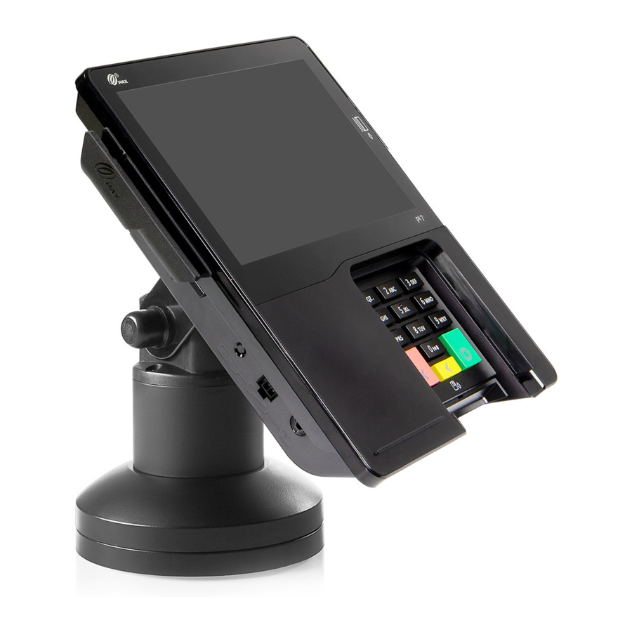
Product Description

- Stylus pen
- Touch screen
- Magnetic stripe reader
- Contactless reader
- Privacy shield
- Keypad
- Smart card reader

- Cable retention clips
- Communication ports
- Speakers
- MAC address label
- Regulatory label
- Part number/ serial number label
- Communication module
Communication ports are labeled and color-coded:

Communication Module
Px terminals that include a default communication module come standard with one Ethernet port and RS232, USB, and PUSB network capabilities. However, if the default communication module is replaced with an optional communication module, your choice of these additional network capabilities are available:
- A second Ethernet port
- Power over Ethernet
- An Ethernet hub
- Wi-Fi and Bluetooth
- Low Energy
- Wi-Fi
Communication module
The communication module is located on the underside of the terminal.


A communication module must be installed before power can be applied to the terminal. Once the new communication module is properly installed, operate the terminal as usual.
Power Connections
Power can be supplied via the power port or a single data cable that carries power. This power can be provided via a "powered cable" where the connected POS terminal provides the power (i.e. PUSB or Power over Ethernet) or by connecting a Px power supply directly to the data cable (i.e. RS232 or USB).
- Power Port
Insert the power connector into the green POWER port. Turn the power connector, locking the tab behind the short plastic wall. Dress the cable through the retention clips. A separate data cable is also required. - POS Cable
Insert the cable connector into the appropriate port on the terminal. Dress the cable through the retention clips opposite the port. Connect power supply to cable as required. The cash register could also supply power to terminal. - Power over Ethernet (PoE)
Power is available over the red LAN1 port when the optional PoE and Ethernet hub communication module is installed. - RS232 port
Insert the RS232 cable into the proper port of the terminal, and route the cable through the retention clips opposite the port, connect port supply to cable as required. The cash register could also supply power to terminal.
Working Environment:
Temperature -10°C ~ 50°C (14°F ~ 122°F)
R.H.: 10% ~ 93% (non-condensing)
Storage Environment:
Temperature -20°C ~ 60°C (-4°F ~ 140°F)
R.H.: 5% ~ 95% (non-condensing)
Stylus Holder and Pen
- Align stylus holder over metal screw openings at left side or top of terminal. Insert tabs into indentations along edge. Attach with captive screws.
- Insert connector end of stylus pen into stylus port on left side of terminal.
- Use enclosed plastic card to press stylus cord into retention clips on left side of terminal.


Privacy Shield
Insert tabs and snap shield firmly in place to left and right of keypad. Not designed to be removable. Removing the shield breaks the retention tabs and the ability to remotely track the status of the shield is lost.
Decorative Plug - If a privacy shield is not installed, a non-removable decorative plug may be installed in its place. This plug does not provide any PIN entry privacy.


If the privacy shield is not installed, you must use PCl-approved alternative methods to secure the PIN pad.
Plugs
Stylus Holder Plug
If required, to prevent stylus pen from being inserted vertically into stylus holder, firmly insert plug into opening in holder, aligning with curve of stylus holder.

Smart Card Reader Plug
If required, insert smart card reader plug into smart card receptacle slot. To remove, if required, gently pry out the plug using a small screwdriver in the slit along top of plug.

Ethernet Plug
An Ethernet plug is included in case you want to block an inactive LAN port. Align plug so that it matches the shape of the port and gently push into opening. To remove, if required, gently pry off using a small screwdriver in the slit along the top of the plug.


Note: LAN2 port is enabled only when Ethernet hub or PoE and Ethernet hub communication module is installed.
Reset Button and Audio Jack
If required, restart the terminal by pressing in and holding the reset button for 2-3 seconds.
If required, a visually disabled person can connect a headphone to the terminal for audio prompting using the 3.5mm output audio jack.

Cable lock
If required, insert customer-provided cable lock into K-Slot®. Loop cable around permanent object to secure in place.

Stand Installation
If required, the P' terminal may be mounted to a stand. Instructions may vary depending on stand specifications.
Carefully route the required cables up through the stand pipe and out the top. Connect the cables to the P' terminal ports.
Insert the three mounting slots on the underside of the terminal into the three metal prongs on the stand base.

Slide the terminal firmly into position, locking the terminal in place on the stand. Secure with fastening screw or locking device as required.

Cleaning the Device

Do not use industrial strength or abrasive cleaner as it may damage or scratch the screen.
Do not immerse device in water (or liquid.)
Do not spray water or cleaner into the MSR slot, Smart Card Reader or ports.
To clean screen, apply distilled water or mild glass cleaner onto a soft, lint-free cloth and gently wipe terminal screen.
To clean terminal, apply distilled water or plastic-safe cleaner onto a soft, lint-free cloth and gently wipe terminal.
Available Accessories


P/N:200312000000228
This document is provided to you for informational purposes only. All features and specifications are subject to change without notice. PAX's name and PAX's logo are registered trademarks o f PAX Technology Inc. The Bluetooth® word mark and logos are registered trademarks owned by Bluetooth SIG, Inc. and any use of such marks by PAX Technology, Inc. is under license. Other trademarks and trade names are those of their respective owners.

PAX Technology Inc.
4901 Belfort Road, Suite 130
Jacksonville, FL 32256, USA
T: 877-859-0099
W: www.pax.us
E: sales@pax.us
Documents / Resources
References
Download manual
Here you can download full pdf version of manual, it may contain additional safety instructions, warranty information, FCC rules, etc.
Advertisement


Need help?
Do you have a question about the Px7 and is the answer not in the manual?
Questions and answers