ICT Digital 2 Series Instruction Manual
Hide thumbs
Also See for Digital 2 Series:
- Instruction manual (2 pages) ,
- Instruction manual (27 pages)

Related Manuals for ICT Digital 2 Series


Summary of Contents for ICT Digital 2 Series
- Page 1 Innovative Circuit Technology Ltd. Digital Series 2 Power Supply Instruction Manual 855-339-000...
- Page 2 Rev 1.0 Jan 2017 Copyright © 2017 Innovative Circuit Technology Ltd. All rights reserved. No part of this publication may be reproduced, stored in a retrieval system or transmitted in any form or by any means, electronic, mechanical, photocopying, recording or otherwise, without the prior written consent of Innovative Circuit Technology Ltd.
-
Page 3: Table Of Contents
Table of Contents PRODUCT DESCRIPTION ........5 INSTALLATION ............6 2.1. Initial Inspection 2.2. Back-up Battery 2.3. Installation 2.4. Remote Control and Monitoring Connections FRONT PANEL CONTROL ........ 10 3.1. Control Panel Keys and Controls 3.2. Setting the DC Output 3.3. Control Panel Menus 3.4. - Page 4 – IMPORTANT SAFETY WARNING! NOTICES Risk of personal injury and property damage! You must exercise caution and follow the safety requirements listed below when using your Digital Series power supply. • The Digital Series Power supply is intended for installation and rack •...
-
Page 5: Product Description
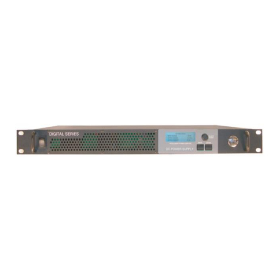
1. PRODUCT DESCRIPTION ICT Digital Series DC power supplies provide high efficiency in a space-saving 1U rack mount design with power factor corrected AC input and extremely low noise output for powering wireless communications and broadband equipment where high reliability is essential. -
Page 6: Installation
Model Numbers and Options: Watts Input Output Output Model Description (Max) 12VDC 100A ICT1200-12SC2 1350 100-265 11.5 - 15.5 Power Supply 24VDC 50A ICT1200-24SC2 1350 100-265 23 - 31.0 Power Supply 48VDC 25A ICT1200-48SC2 1350 100-265 47- 62.0 Power Supply 12VDC 50A ICT600-12SC2 100-265 11.5... -
Page 7: Back-Up Battery
2.2. Back-up Battery An external lead-acid battery with the same nominal voltage as the power supply may be connected directly in parallel with the output terminals, or to the BAT terminal (on units with the LVD option ) to provide a DC backup capability. Use appropriate wire, over current protection and disconnect device as outlined in the Installation section. -
Page 8: Installation
ICT to compensate the charge voltage so that hot batteries are not overcharged, and cold batteries receive adequate charge. 2.3. Installation The ICT Digital Series Power Supply is designed to be used in an industry standard cabinet or other restricted access location. -
Page 9: Remote Control And Monitoring Connections
When using the LVD option in a positive ground system do not ground the positive terminal of the battery. The system must only have a single ground connection, normally located at the distribution or load point. An additional ground connection at the battery will allow current to bypass the internal LVD contactor preventing disconnection of the battery during a low voltage event. -
Page 10: Front Panel Control
Connect the optional remote battery temperature monitor probe (ICT-TMP) (for use on LVD equipped models) to pin 4 and 5, to automatically compensate the charging voltage according to the battery temperature. Apply the probe body to the side of the middle battery case using the provided adhesive backed clamp. -
Page 11: Control Panel Keys And Controls
Energize the external AC source, and push the front panel battery disconnect device if an external battery is used. Check that the front display is lit, and an initial start-up screen appears, which is then replaced with the system status screen shown below. -
Page 12: Setting The Dc Output
pressed while modifying the value for a setting, that setting will not be saved. For a detailed description of the Control Panel screens and menus, see the Control Panel Menus section. 3.2. Setting the DC Output To set the output voltage, current limit, and enable the output, do the following: 1. -
Page 13: Control Panel Menus
3.3. Control Panel Menus Home Screen SYSTEM STATUS INPUT VOLTAGE: 118V OUTPUT VOLTAGE: 13.8V OUTPUT CURRENT: 32.0A Scroll SYSTEM SETTINGS SYSTEM SETTINGS TURN OUTPUT ON/OFF OUTPUT VOLTAGE: 13.8V OUTPUT VOLTAGE: 13.8V DC OUTPUT: CURRENT LIMIT: 80.0A Push ENTER CURRENT LIMIT: 80.0A Push ENTER <SCROLL>... - Page 14 Input Voltage: Displays the AC input voltage. Voltage display will blink during an AC voltage failure. The Value can range from 100-265 Output Voltage: Displays the DC output voltage. Voltage display will blink during an output voltage failure. Output Current: Displays the output current. Current display will blink when the power supply is in current limit.
- Page 15 SECURITY SETTINGS SCREEN SECURITY SETTINGS SET PASSWORD CLEAR PASSWORD SET LOCKOUT TIMER The Security Settings screen allows you to set a Control Panel menu password to prevent unauthorized changes to the power supply settings. After the Control Panel menu password is set, you will be prompted for the password when attempting to change the power supply settings.
- Page 16 PARALLEL SETTINGS SCREEN PARALLEL SETTINGS MODE: STANDALONE DEVICE ID: UNITS IN PARALLEL: See the Smart Parallel Operation section for more information on configuring the parallel settings. (This screen is only shown if parallel connected units detected.) Parallel Mode: Modifies the parallel mode setting. It has 3 options: Standalone: Single Unit.
- Page 17 View Device Name: Default is ICT DIGITAL SERIES . The device name can only be changed on the Ethernet GUI network page. Reset Comm Settings: Resets the Web server Administrator password, IP address, and port settings to the original factory default values.
- Page 18 TEMP-CO/cell: Set the float voltage temperature compensation (-mV/cell/°C), when using the optional remote temperature sensor (ICT-TMP) Typically use -4mV/cell/°C (i.e. compensates charge V at -24mV/°C for a 12V battery) for lead- acid AGM type batteries. Check the battery data sheet for the recommendations before setting.
-
Page 19: Control Panel Menu Password Reset
Duration: Set the maximum time (in minutes) for the equalize charge to be applied, as recommended by the battery manufacturer. Status: Set to Start, to begin an equalize charge when the battery is fully charged. (Status will be READY if battery is fully charged. -
Page 20: Administrator Password / Ip Address Reset
4. SMART PARALLEL OPERATION If your load requires more power than can be supplied by a single ICT Digital Series power supply, two or more power supplies (maximum 6) of the same output voltage rating can be connected in parallel in a Master-Slave configuration to increase the power available, using the SHARE ports on the back of the units. -
Page 21: Share Interface Connector
Up to six power supplies of the same output voltage rating can be connected in parallel to provide up to six times the total output power capability of a single unit. An optional bus bar set (ICT-PAR) is available to simplify connection of two units in parallel. When... -
Page 22: Connecting The Power Supplies In Parallel
1. Power each unit up independently. In the Control Panel menu, scroll to the Parallel Settings screen and press Enter. 2. Scroll to the Parallel Mode setting and press Enter. Scroll and choose a parallel mode setting, then press Enter. One unit must be configured as a Master, and the remaining units must be set to Slave. - Page 23 1. After configuring each power supply for parallel operation, turn the Power Switch on all units to the OFF position. together at a common positive load point using the optional ICT- PAR parallel straps (shown above). See figure 4. together at a common negative load point using the other ICT- PAR parallel strap (as shown above).
-
Page 24: Advanced Parallel Operation With Tcp/Ip Ethernet Connection
Control Panel display. System Settings screen. The Output Voltage, Current Limit, and Output Enable of all units are set in unison here. The Output Settings screen on all of the Slave units will be locked out. 4.4. Advanced Parallel Operation with TCP/IP Ethernet Connection View the following settings and information on the Device Setup page using a TCP/IP Ethernet connection to a unit: (see section 5) -
Page 25: Changing A Power Supply Back To A Standalone Unit
4.5. Changing a Power Supply Back To a Standalone Unit To release a unit from parallel operation and change it back to a Standalone unit, do the following: 1. Turn the Power Switch on all parallel units to the OFF position. 2. - Page 26 DHCP, it will use a default IP address of 192.168.0.181. You can also find the IP address of any ICT unit connected to a network by running the ICT IP Address Discovery Utility app on any Windows based computer connected to the same network. This tool is available for download on the ICT Website: http://www.ict-power.com/tools-utilities/...
-
Page 27: System Status
View the Battery Status section of this page to check the battery voltage, battery current (+ for charging, - for discharge), battery temperature (if the optional ICT-TMP sensor is installed), and status of the LVD battery contactor (connected, or disconnected). -
Page 28: Battery Backup
Output Voltage Control: automatically adjust the output voltage of the power supply according to the battery temperature, when the optional temperature probe (ICT-TMP) is installed. Temperature Coefficient/cell: set the desired temperature change in -mV/°C per cell, according to the battery The default setting of 0mV disables the compensation. - Page 29 Battery Charge Current Limit: Limit the maximum battery charge current provided through the optional Battery LVD port, while still allowing the full rated current to be drawn from the main output. Charge Current Limit: Set the maximum charge current (A) as recommended by the battery manufacturer.
- Page 30 Next Equalize Charge: The scheduled date of the next Equalize charge, if an Equalize Interval has been set. This set up. LVD Settings: Set the battery Low Voltage Disconnect and Re- connect thresholds and LVD alarm functions here, for units with the optional LVD battery port.
-
Page 31: Device Setup
5.4. Device Setup This page allows you to change the name of the supply, configure the parallel operation settings, and set the date and time and data- logging function of the power supply. Click on the Save Settings button to record any changes made to parameters on this page. Device Name: Enter a unique descriptive name for the power supply if desired. -
Page 32: Network Setup
operations. (e.g. North American Pacific Time is GMT-8:00 hours) Set Time Manually: Tick this box to manually set the date and time used by the unit, if desired, then enter the correct local time and date in the boxes provided. Data Logging: Enable data Logging by selecting Enabled in the drop down menu, to record up to the last 30 days of voltage, current and alarm data, recorded once per minute. - Page 33 Primary DNS: Specify the IP address of the Primary DNS Server for your network. Secondary DNS: Specify the IP address of the Secondary DNS Server for your network. Web Server: Configure the internal Web Server port parameters here. The Web server port numbers can be changed to any port within the range 1 65565.
-
Page 34: Email Setup
SNMP queries. This information is optional. 5.6. Email Setup The ICT Digital Series is capable of sending email alarm notifications to multiple email addresses. Configure these settings if you would like to receive e-mail alarm notifications from the power supply. The information for the following settings is available from your Network Administrator or Internet Service Provider (ISP). -
Page 35: Alarm Setup
SMTP Port: The port used by your SMTP server. The standard port used by most SMTP servers is 25. SMTP Server requires SSL: Check this box if your SMTP server requires an encrypted SSL connection. Sender E-mail Address: Enter the e-mail address you wish to appear as the sender of the e-mail notifications. - Page 36 The e-mail settings on the Network Setup page must be configured correctly before any e-mail notifications can be sent. DC OUTPUT FAILURE ALARM The alarm latches the output off, and clears when the DC output is manually re-enabled. Activate Alarm Form C Contact: If this box is checked, the ate a fault condition when the Output Voltage or current rises above approximately 110% of the max-rated output.
-
Page 37: User Setup
Send E-mail: If this box is checked, an e-mail alarm notification will be sent when an over-temperature failure occurs. PARALLEL UNIT OFFLINE ALARM This alarm does not affect the supply output state. Activate Alarm Form C Contact: If this box is checked, the condition if communications is lost between any units connected together through the serial interface. -
Page 38: Maintenance
Control: User has read-only access to the panel, but can enable or disable the output, and change some of the basic settings. Cannot change passwords or network settings. View-Only: User can only view status, cannot change any settings New Password: Allows you to change the password for the selected user. -
Page 39: Router Configuration
Firmware Update Download the latest Digital Series 2 firmware file from the ICT website (ict-power.com) to your local computer. De-compress this .cry file then press the Update Firmware button, and link to this file. Update the firmware on the power supply by clicking the Update Now button. - Page 40 d. Enter the local IP address of the power supply (e.g. 192.168.0.181) in the IP Address field. The current IP address of the power supply can be found on the Network Status screen (see the Control Panel Menus section for more information).
-
Page 41: Text Message Alarm Notifications
5.11. Text Message Alarm Notifications The Digital Series Power Supply can send text message alarm notifications to a cell phone by sending the alarm e-mail to an address at the mobile phone provider. On the Network Setup page, enter the address for your phone in one of the -mail Address fields. -
Page 42: Network Troubleshooting
5.12. Network Troubleshooting I am unable to access the embedded Web server: Check that you are using the correct IP address to access the Network Status screen on the Control Panel display (see the Control Panel Menus section for instructions on how to access the Network Status screen). - Page 43 There must be valid e-mail addresses in the Recipient E-mail Address and Sender E-mail Address fields. Do not enter more than one e-mail address in the Sender field. If your SMTP server requires authentication, ensure that the SMTP User Name and SMTP Password fields are entered correctly.
- Page 44 Troubleshooting Parallel Operation alarms and errors: Alarm message: Possible Cause: Parallel Unit Offline A unit connected to the RS485 bus has lost power. A RS485 data cable has been unplugged or damaged. A communications reset has been done to a unit connected to the RS485 bus.
-
Page 45: Product Specification
6. PRODUCT SPECIFICATION Table 2: Product Specification for all models Input Voltage 100 - 265VAC, 50 or 60Hz Input Power Factor 0.99 Typical Line Regulation 0.1% Load Regulation 0.5% Current Limit -0/+4% of nominal max limit Positive ground, negative ground, or Grounding floating output allowed Operating Temperature... - Page 46 Table 3: Model Ratings Rating 12V 50A 24V 50A 24V 25A 48V 25A 48V 12.5A 100A ICT1200 - ICT600 - ICT1200 - ICT600 - ICT1200 - ICT600 - Model Output Voltage 11.5V- 11.5V- 23.0V 23.0V 46.0V 46.0V adjustment 15.5V 15.5V 31.0V 31.0V 62.0V...
-
Page 47: Limited Warranty
In no event will ICT be liable for any damages resulting from the use of or the inability to use the ICT product, even if an ICT employee or an authorized ICT dealer has been advised of the possibility of such damages, or for any claim by any other party. - Page 48 INNOVATIVE CIRCUIT TECHNOLOGY LTD. 26921 GLOUCESTER WAY LANGLEY, BRITISH COLUMBIA, CANADA V4W 3Y3 T 604.856.6303 F 604.856.6365 www.ictcorporate.com...
Need help?
Do you have a question about the Digital 2 Series and is the answer not in the manual?
Questions and answers