Table of Contents
Advertisement
Quick Links
Advertisement
Table of Contents

Subscribe to Our Youtube Channel
Related Manuals for ICT Hybrid Ultra ICT-2U4-DC12


Summary of Contents for ICT Hybrid Ultra ICT-2U4-DC12
- Page 1 Hybrid Ultra Instruction Manual 855-350-050...
- Page 2 Hybrid Ultra SAFETY GUIDELINES Principles of Safe Operation and Maintenance Safety must always be the top priority of all personnel involved in the installation, operation, and maintenance of this unit as it operates at high voltages that could be potentially lethal. Technicians must adhere to the appropriate standards and manufacturer’s recommendations to minimize hazards.
- Page 3 Hybrid Ultra General Alerts Risk of serious personal injury or damage to equipment and property. Always observe the following: • Install and operate unit in a restricted access location. A restricted access location is an area to which access can be gained only by service personnel using a special tool, lock and key, or other means of security and which is controlled by the authority responsible for the location.
- Page 4 • Consult with manufacturers of surge suppression devices to select appropriately rated protection device(s) and proper installation methods. • ICT’s product warranty does not cover damage caused by power surges and electrostatic discharge events including lightning. 855-350-050_Rev2.0_Instruction Manual...
- Page 5 Hybrid Ultra NOTE: Due to the breaker-detection circuitry internal to the unit, it may be possible to measure a voltage on the terminal(s) with no load connected, even if that terminal’s breaker is open circuit. This is normal operation. The breaker-detection circuitry is a high- impedance circuit, and while a voltage may be present on the output terminal, it is a signal voltage and does not support loading.
- Page 6 Innovative Circuit Technology Ltd. Disclaimer ICT shall not be held liable for any damage or injury involving this product if it has been subjected to misuse and exposure to environmental conditions not conforming to the product’s limits of operation, improper installation, or maintenance.
- Page 7 Hybrid Ultra ICT LIMITED WARRANTY The warranty period on ICT products is two (2) years from date of purchase from an authorized ICT reseller or OEM with valid proof of purchase, or from date of shipment from the ICT manufacturing facility. The warranty period for a repaired product or part is ninety (90) days or the remainder of the unexpired term of the new product warranty period, whichever is greater.
- Page 8 Hybrid Ultra In no event shall ICT be liable for any special, indirect, or consequential damages such as, but not limited to, loss of use, business or goodwill, loss of revenue, or loss of profits, which may result, either directly or indirectly, from defects in products provided by ICT.
-
Page 9: Table Of Contents
Hybrid Ultra TABLE OF CONTENTS 1.0 INTRODUCTION ................... 1 System Components and Features..........1 1.1.1 Intelligent Control Module (ICM) ........2 1.1.2 Power Module ..............2 1.1.3 Battery Management Module (BMMD) ......2 1.1.4 DC-DC Converter Module ..........2 1.1.5 Load Distribution Module (LDM) ........3 1.1.6 Power Chassis ............... - Page 10 Hybrid Ultra Status Indicators and Alarms ............ 34 4.0 OPERATION: GRAPHICAL USER INTERFACE ....... 37 Log In/Log Out ................37 System ..................38 4.2.1 STATUS ............... 39 4.2.2 SETTINGS & CONTOL ..........41 Power Modules ................42 DC Converter ................43 4.4.1 STATUS ...............
- Page 11 Hybrid Ultra LIST OF FIGURES Figure 1. A Typical Hybrid Ultra Configuration ..........1 Figure 2. Typical Rear View ................ 6 Figure 3. The DC Output Bus Bars ............. 9 Figure 4. The LDM Output ................9 Figure 5. The LDMP Output ................ 9 Figure 6.
- Page 12 Hybrid Ultra Table 24. Default Equalize Voltage Settings ..........49 Table 25. Default Disconnect Voltage Settings ......... 51 Table 26. Default Reconnect Voltage Settings .......... 51 Table 27. The minimum difference between Disconnect and Reconnect voltages ..................... 51 Table 28. Deeply discharged battery values (typical)........ 52 Table 29.
-
Page 13: Introduction
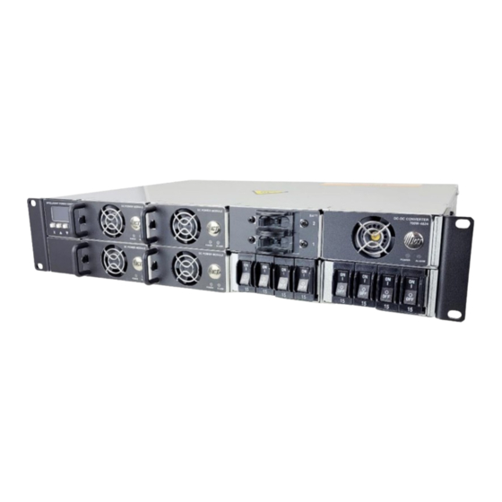
Hybrid Ultra 1.0 INTRODUCTION The Hybrid Ultra is a flexible, N+1 redundant DC power system with intelligent networked control, advanced battery management, managed load distribution options, and a 12- or 24-volt integrated DC-DC Converter Module in a pre-configured 2RU rack mount chassis. The power chassis features a factory-installed Intelligent Control Module (ICM) with front graphic display and up to five parallel-connected hot-swappable 700- or 1,500-watt, 24- or 48-volt Power Modules, for a combined 7,500 watts or... -
Page 14: Intelligent Control Module (Icm)
Hybrid Ultra 1.1.1 Intelligent Control Module (ICM) • High resolution OLED display with intelligent front panel controls fully integrated into power chassis • TCP/IP Ethernet communications port • Embedded web server with easy-to-use graphical user interface (GUI) • Intelligent monitoring, reporting and control of system and all installed modules •... -
Page 15: Load Distribution Module (Ldm)
Six bolt/washer/nut sets for connections to the output bus bars (in bag) • RJ11 data cable (ICT-JMP) (in bag) • Remote battery temperature sensor (ICT-TMP) included when a BMMD is installed in the system (in bag) 855-350-050_Rev2.0_Instruction Manual Page 3 of 84... -
Page 16: Tools And Parts Needed
Hybrid Ultra 2.2.1 Tools and Parts Needed • Two 7/16-inch wrenches • Wire stripper • Four #10-32 Phillips screws (length to be decided by installer) to connect rack ears to rack • #2 Phillips screwdriver for the rack-ear connections and output bus bar cover •... -
Page 17: Table 2. Power Chassis Models
Intelligent Power Chassis with integrated Control Module and Ethernet communications, includes dual 100 A battery disconnect breakers and 150 A ICT-2U4-DC12 ICT-2U4P-DC12 Low Voltage Disconnect, a 700 W 12 V integrated DC-DC Converter Module, 8 x 25 A (max.) outputs, accepts up to four... -
Page 18: Rack Mounting
Hybrid Ultra Description Model No. 25 A circuit breaker for LDM ICT-CB25 30 A circuit breaker for LDM ICT-CB30 Blanking plate for unused power module positions (snap-in) ICT-BPM Battery temperature sensor (1pc included with Power System/BMM) ICT-TMP Secondary power shelf output bus bar jumper strap (for parallelling two... -
Page 19: Sensor And Alarm Connections
Hybrid Ultra All DC outputs of ICT’s DC power systems are isolated from chassis ground (floating). DC output returns can remain isolated from ground (DC-I) or can be grounded (DC-C), as per site grounding requirements and/or local or national electrical codes. -
Page 20: Load Connections
Hybrid Ultra Mount the sensor to the mid-level side of the middle battery in a battery bank using the adhesive-backed clip. The rate of voltage compensation can be adjusted through the ICM front display panel interface, or the GUI in the Battery Backup Settings section. The default compensation is 0 mV/C per cell (no compensation). -
Page 21: Figure 3. The Dc Output Bus Bars
Hybrid Ultra Figure 3. The DC Output Bus Bars If using the LDM outputs, an "Output" (labelled + or − depending on polarity) and "Return" (labelled RTN) connection are provided for each channel (see Figure 4 and Figure 5). Figure 4. The LDM Output Figure 5. -
Page 22: Figure 6. The 24-Volt Dc-Dc Converter Module Output Bus Bars
Connecting an inverter in this way may void the product warranty. ICT recommends connecting a DC-AC inverter to the battery bank. 1. Locate the four controlled outputs on the LDM rear panel connector block. -
Page 23: Battery Connections
Hybrid Ultra The DC-DC Converter Module provides up to 700 watts output power which is drawn from the Hybrid Ultra’s primary voltage bus. The max current rating is shown in Table 9. Table 9. DC-DC Converter Module Output Capacity Converter Voltage Converter Output Capacity 12 V 50 A... -
Page 24: Table 10. Default System Output Settings
Hybrid Ultra • Only use the Equalize Charge setting for flooded lead-acid batteries in a well-ventilated location. Do not use Equalize Charge on sealed batteries. Always consult with battery manufacturer and observe all battery manufacturer recommendations. • Do not tie either of the unit main outputs to the BAT terminal on the BMMD, as this may short circuit the battery or bypass the internal LVD circuitry in the BMMD. -
Page 25: Figure 7. The Bmmd Output Bus Bars
Hybrid Ultra 2. Verify the polarity of the BMMD installed in the unit by noting the label under the rear BMMD BAT bus bar input. "BAT +" indicates a positive battery voltage system with the LVD contactor and battery breaker internally connecting this terminal to the system "+" output, while "BAT –"... -
Page 26: Installation Of The Breakers
Hybrid Ultra 2.10 Installation of the Breakers If the breakers are not fully installed or are not installed “square” they may cause intermittent power loss or unexpected behavior for the load devices. CAUTION Install breakers in the four front locations of the LDM by inserting into the four breaker openings ("On"... -
Page 27: Installation Of The Power Module
Hybrid Ultra 2.11 Installation of the Power Module Release Latch Figure 11. Installing Power Module in a Hybrid Ultra Risk of personal injury or damage to equipment and property. Always observe the following: • Ensure the unit has the correct polarity for the application (see Table 2). -
Page 28: System Wiring Final Verification
The latch is located under the module handle (see Figure 11). 4. Install an optional blanking plate (ICT-BPM) into any unused Power Module positions to prevent accidental access to the internal circuitry of the system. -
Page 29: Software Configuration
Hybrid Ultra Table 12. AC Source Wiring Connections AC Voltage 3-Conductor Cord Connection to ICT Unit Line Line to Line 120/240 VAC Neutral Neutral to Neutral (Single-Phase) Ground Ground to Ground Line1 Line 1 to Line 240 VAC Line 2... -
Page 30: Operation: Front Display Panel
Hybrid Ultra 3.0 OPERATION: FRONT DISPLAY PANEL Switch on the external AC power source circuit breaker; check that the green POWER LED is lit on each Power Module; and that the Intelligent Control Module (ICM) front graphic display is lit. The Hybrid Ultra will start up and operate at the factory default settings when AC power is connected, generally requiring no other set up or adjustment for basic operation. -
Page 31: Menu Structure
Hybrid Ultra 3.2 Menu Structure See the complete menu structure in the following diagram. Navigate through the various screens using the four interface buttons. MAIN SCREEN SYSTEM STATUS SYSTEM SETTINGS INPUT VOLTAGE 120V OUTPUT VOLTAGE 55.2V ADJUST SETTINGS OUTPUT VOLTAGE 55.2V CURRENT LIMIT OUTPUT CURRENT... -
Page 32: Figure 14 (Cont'd). Icm Menu Structure (Cont'd From Previous Page)
Hybrid Ultra LDM MODULE X LDM MODULE X SETTINGS LDM MODULE X CHANNEL ENABLE CHANNEL 1 8.0A CHANNEL ENABLE CHANNEL 1 CHANNEL 2 2.5A CHANNEL OVERCURRENT CHANNEL 2 CHANNEL 3 CHANNEL UNDERCURRRENT CHANNEL 3 CHANNEL 4 3.5A CHANNEL 4 ADJUST SETTINGS LDM MODULE X OVERCURRENT CHANNEL 1 15.0A... -
Page 33: System Status
Hybrid Ultra 3.2.1 System Status The main system status screen will show the most current operating conditions for the unit, primarily the Input Voltage (VAC), the Output Voltage (VDC), and the total Output Current (A). Other information will be shown depending on the operating state of the unit: •... -
Page 34: Battery Management Module
Hybrid Ultra Voltage and Current Limit (see System Settings section) to match the battery type and system load requirements if required. 3.2.2 Battery Management Module The BMMD Status Screen indicates the Battery Voltage (VDC), the combined Battery Current, and the approximate battery State of Charge (%) for lead-acid batteries or a bar graph showing relative magnitude of the total battery current for lithium-ion batteries. -
Page 35: Table 14. Default Disconnect Voltage Settings
Hybrid Ultra Scroll to highlight the parameter or sub- menu to change. • LVD Disconnect V • LVD Reconnect V • Charge Current Limit • Overcurrent Alarm level • Battery Type • Battery Capacity (Ah) rating • Battery discharge rate (hrs.) used for capacity spec. -
Page 36: Table 15. Default Reconnect Voltage Settings
Hybrid Ultra Table 15. Default Reconnect Voltage Settings Module ICT700-24PM ICT700-48PM ICT1500-24PM ICT1500-48PM Threshold Voltage 25.0 VDC 50.0 VDC Table 16. The Minimum Difference Between Disconnect and Reconnect Voltage 24 VDC Units 48 VDC Units CHARGE CURRENT: Set the "Battery Charge Current Limit" to limit the maximum battery charge current provided, while still allowing the full rated current to be drawn from the main output. - Page 37 With lithium-ion batteries, this feature is built into the BMS. TEMP-CO/cell (only available for lead-acid batteries): Ensure the Battery Temperature Sensor (ICT-TMP) is installed and connected to the battery case (see Section 2.7) for optimal lead-acid battery charging and best battery life. Set the "Temperature Compensation/°C" level per battery cell to match the recommendation of the battery manufacturer (−4 mV/°C per cell is typical).
- Page 38 Hybrid Ultra Scroll to highlight parameter in selected sub-menu. • Voltage • Duration • Status (display only) Press Enter to select. Use the Up/Down buttons to adjust setting, press Enter to set value and return to previous screen. Press Back to return to previous screen without saving changes.
-
Page 39: Integrated Dc-Dc Converter Module
Hybrid Ultra Use the Up/Down buttons to adjust setting, press Enter to set value and return to previous screen. Press Back to return to previous screen without saving changes. NOTE: A Battery Discharge Test of a fully charged battery can be manually initiated by changing the discharge test Status parameter to "Enabled". -
Page 40: Load Distribution Module
Hybrid Ultra Table 17. The Default Output Voltage and Current 12 V DC-DC Converter 24 V DC-DC Converter Module Module Default Output Voltage 13.8 V 27.6 V Default Output Current 50 A 25 A 3.2.4 Load Distribution Module The LDM Status screen shows the output current for each of the four outputs. -
Page 41: Alarm Inputs
Hybrid Ultra Press Back to return to LDM Settings screen. Scroll to highlight the sub-menu to change (Output Undercurrent). Press Enter to select. Scroll to highlight Output to be adjusted. Press Enter to select. Use the Up/Down buttons to adjust setting, press Enter to set value and return to previous screen. -
Page 42: Alarm History
Hybrid Ultra 3.2.6 Alarm History The Alarm History screen displays a log of the 20 most recent alarm events. These alarms may have been raised by any module experiencing an alarm, or by one of the four external Alarm Inputs being triggered. Other information will be shown depending on the operating state of the unit: •... - Page 43 Hybrid Ultra Advanced Options Use the Advanced Options screen to set or clear the LCD Password, Comm Control Restart and Reset Comm Settings. Scroll to choose parameter or sub-menu. • LCD Password Setup • Comm Control Restart • Reset Comm Settings •...
- Page 44 Hybrid Ultra RESET COMM SETTINGS: Reset the admin password, port settings, and IP address to the factory defaults by pressing the "YES" button in the Reset Comm Settings. Press Enter button. Scroll to choose. Press Enter or Back to exit with no change. Scroll to choose.
-
Page 45: Notification Screens
Hybrid Ultra 3.2.8 Notification Screens Alarm Notification When the unit triggers an alarm, the front display panel will be over-written by the Alarms Active screen. Press Back to return to the previous screen, press Enter to jump to the Alarm History screen. Alarms will be shown as they occur, press Back button to return to the previous... -
Page 46: Status Indicators And Alarms
Hybrid Ultra 3.4 Status Indicators and Alarms The status of the Hybrid Ultra is indicated on the front display panel module on units equipped with an ICM, or via the network GUI (see Section 4) on remotely monitored units. It is also available through SNMP (see Section 4.8.2). -
Page 47: Table 19. Battery Management Module (Bmm) Alarms
Hybrid Ultra Alarm Trigger Condition Module Green Alarm Send Condition Output Relay E-mail Internal bus voltage out of Disabled Shutdown range Internal aux Module Fault voltages out of Disabled Active range Over Temp Internal temp too Disabled Active Shutdown high Output above set DC Output point (Manually re-... -
Page 48: Table 20. Dc-Dc Converter Module Alarms
Hybrid Ultra Table 20. DC-DC Converter Module Alarms Alarm Module Green Alarm Send Trigger Condition Condition Output Relay E-mail Loss of AC and Module Power DC bus Disabled Active Failure connection Module Normal Operation Enabled Operating Current Limit Output current (warning only, approaches within Enabled... -
Page 49: Operation: Graphical User Interface
Hybrid Ultra Alarm Output Alarm Send Trigger Condition Condition Relays Required Relay E-mail Output Output current rises Closed Active Overcurrent above setting for 5 s Configuration LDM in wrong slot or Active Error mixed polarity with BMM change Load V drops below Load Open Active Shedding... -
Page 50: System
NOTE: Take note of the assigned IP address displayed and use this in the browser address field to access the unit remotely. The IP address of any ICT unit on a local network can be found by running the ICT "IP Address Discovery tool", after installing it on a Windows computer connected to the same network (tool available for download from ICT http://www.ict-power.com/resources/tools-... -
Page 51: Status
(BMMD). Battery Temperature: Shows the temperature measured on the optional ICT Battery Temperature Probe (ICT-TMP). Net Ah Count: Shows the Ah that have been consumed from the battery. Will display 0 Ah if the batteries are fully charged. Only displayed when the unit is configured for lead-acid batteries. - Page 52 Hybrid Ultra Run-time Remaining: Shows the estimated time in hours and minutes before the battery is discharged. This is blank if the batteries are charging. Only displayed when the unit is configured for lead-acid batteries. Battery State of Charge: Shows the estimated state of charge in %. The system resets the SOC to 100% whenever it detects that the battery is at the rated Float Voltage with minimal charge current for at least 24 hr.
-
Page 53: Settings & Contol
Hybrid Ultra 4.2.2 SETTINGS & CONTOL This tab is used to adjust the System Output Settings. DC Output Status On/Off Buttons: Use these to remotely disable the system output by shutting off all Power Modules. The default setting is Enabled. Auto-Restart Button: Use this button to momentarily shut off the main output, and then restart automatically after a time delay (set in the "Auto- Restart Delay"... -
Page 54: Power Modules
Hybrid Ultra Auto-Restart Delay: Set the delay time (5 to 240 s) that the output will remain off when output is remotely disabled using the "Auto-Restart" button. The unit will automatically restart after the Auto-Restart Delay period. The default setting is 15 seconds. NOTE: The output voltage and current limit settings apply to the combined output of all installed Power Modules. -
Page 55: Dc Converter
Hybrid Ultra 4.4 DC Converter Use this tab to see the status of integrated DC-DC Converter Module. 4.4.1 STATUS This tab shows the alarm status, output voltage, and output current of the integrated DC-DC Converter Module. The graphic will display green for an installed module that is working as expected;... -
Page 56: Settings & Control
Hybrid Ultra Alarm Status: Shows status of the DC-DC Converter Module (Alarm or OK). 4.4.2 SETTINGS & CONTROL This tab is used to configure the settings for the DC-DC Converter Module. DC Converter Output Status On/Off Buttons: Use these to remotely disable the DC-DC Converter Module. -
Page 57: Battery Backup
Hybrid Ultra connected to the DC-DC Converter Module. The default setting varies based on the DC-DC Converter Module installed (see Table 23). Alarm Reporting Send E-mail: Select the check box to have an e-mail sent to the e-mail addresses set up on the communications page whenever an alarm is triggered on the integrated DC-DC Converter Module (see Section 4.8.3). - Page 58 This number represents both batteries if this is a dual BMM (BMMD). Battery Temperature: Shows the temperature measured on the optional ICT Battery Temperature Probe (ICT-TMP). If no probe is installed, the unit will default to 25°C. Net Ah Count: Shows the Ah that has been consumed from the battery.
-
Page 59: Settings & Contol
Hybrid Ultra LVD Disconnect Voltage: Shows the battery voltage when the LVD will disconnect the battery. LVD Reconnect Voltage: Shows the battery voltage when the LVD will reconnect the battery. LVD Status: Shows the status of the LVD (Open or Closed). Alarm Status: Shows status of the batteries (Alarm or OK). - Page 60 The default setting is 0 mV/°C. NOTE: The system must have the battery temperature sensor (ICT-TMP) installed on the battery for this setting to have an effect (default setting is 0 mV, assumes 25°C operation).
-
Page 61: Table 24. Default Equalize Voltage Settings
Hybrid Ultra Risk of serious personal injury or damage to equipment and property! Always observe the following: • Equalize charging is intended for flooded lead-acid batteries only and may produce higher than normal levels of hydrogen gas. • Consult with the battery manufacturer when using SLA batteries. - Page 62 Hybrid Ultra Equalize Interval: Set the time in days (0–180 days) between automatic equalize charges. Set this time to 0 to disable the automatic equalize charge. The default setting is 0 (Disabled). Day of Week: Set the day of the week that the automatically recurring equalize charge should take place or select "Any"...
-
Page 63: Table 25. Default Disconnect Voltage Settings
Hybrid Ultra voltage. The battery is reconnected when AC power is restored or after recharging to a preset threshold. Disconnect Voltage: Set the threshold to a level that will protect the battery from excessive discharge (as recommended by the battery manufacturer). -
Page 64: Table 28. Deeply Discharged Battery Values (Typical)
Hybrid Ultra Table 28. Deeply discharged battery values (typical) 24 VDC Units 48 VDC Units 20 VDC 40 VDC Battery Over-Current Alarm Over-Current Threshold: Set the threshold to receive an alarm notification when the battery discharge or charge current exceeds a set overcurrent level. - Page 65 Hybrid Ultra Send E-mail: Select the check box to have an e-mail sent to the e-mail addresses set up on the communications page for an alarm condition (see Section 4.8.3). The default setting is Disabled. Battery Discharge Test (only available on lead-acid batteries) Configure the Battery Discharge Test settings in this section to either manually or automatically perform a partial discharge test to gauge the relative capacity of the external lead-acid battery.
-
Page 66: Table 29. Default Discharge Voltage Limit Settings
Hybrid Ultra A "Discharge Test Failure" notification indicates the battery is unable to power to load for the set duration. The connected load devices should continue to run normally while the discharge test is running. This test must only be done when AC power is present during the test and for an adequate time after the test to allow for a full recharging of the battery. -
Page 67: Load Distribution
Hybrid Ultra A discharge test will immediately fail if the unit loses AC power. The log will show that the test failed. Manual Discharge Test: Press this button to manually initiate a Battery Discharge Test of a fully charged battery. NOTE: System will state that the discharge test is Not Ready if the battery SOC is less than 100%. -
Page 68: Status
Hybrid Ultra The graphic will display green for an installed LDM that is working as expected; a red display for an installed module that has an active alarm; and will be grey when a module is not installed in that slot. 4.6.1 STATUS This tab shows the operating status and current loads of the circuit-breaker controlled outputs on the LDM module. - Page 69 Hybrid Ultra Module Output Control Each output on the LDM will be displayed with name and status. A green Enabled indicates the electronic relay on that output channel is closed or turned on. A red Disabled indicates that the electronic relay is open or turned off (Enabled or Disabled).
- Page 70 Hybrid Ultra Module Output Configuration NOTE: Each output on the LDM has an individual screen. Any changes made below will only affect the selected output. Save Setting before changing the selected output. Select an Output to edit Select the output to be edited in this section. Make any required changes, and then click on the Save Settings button at the bottom of the page to save any edits.
- Page 71 Hybrid Ultra Output State after Power Loss: Sets the state for the output after the LDM loses all input power, then recovers. The default setting is Restore Last State. Select one of the following: • Restore Last State: This will return the output relay to the state prior to the reset event (default).
- Page 72 Hybrid Ultra least 1.5 V above the "Load-Shedding Threshold" voltage. The default setting is 50-volt DC. Enable Load-Shedding upon AC Failure condition: Select this box to disable the output when an AC failure condition regardless of DC voltage levels. If this option is selected, the Load-Shedding DC bus voltage thresholds are not used and will be greyed out.
-
Page 73: Alarms
Hybrid Ultra 4.7 Alarms Use this tab to see the alarms on this unit and to control their settings. 4.7.1 STATUS This tab shows all active alarms and up to 32 historic alarms. The history will be cleared after the ICM is rebooted. Active Alarms Shows the module that the alarm is on;... -
Page 74: Communications
Hybrid Ultra Alarm Input # Alarm Name: Set a meaningful name to suit the installation (these will be used for e-mailed alarm messages). Contact Type: Set the form-C behavior for each device to be monitored. (Not Used, Normally Open, Normally Closed) Select Not Used for all unused alarm input channels. - Page 75 Hybrid Ultra Serial Number: Shows the serial number. Date and Time Settings Current System Time: Shows the current system date and time. Synchronize with NTP Server: Select the check box to synchronize with NTP Server. The default is Enabled. NTP Server: Set an NTP server address here (i.e., time.nist.gov) to automatically load network time.
-
Page 76: Network Setup
Hybrid Ultra Secondary IP Address: Set a secondary IP address for the unit to ping to determine whether the network is functioning. Watchdog Timeout: Set a time in minutes (1–80 minutes) for the unit to wait with no ping response from either IP address before initiating a reset. - Page 77 Hybrid Ultra Saving any changes to the network settings will cause the ICM to re-start, causing momentary loss of communications. NOTICE Network MAC Address: Shows the MAC address assigned to the unit. It is also shown on the LCD Network Status screen. Enable DHCP: Select the check box if the network uses a DHCP server to automatically assign IP addresses.
- Page 78 The information available from the SNMP agent is described in a MIB (Management Information Base) file, which can be downloaded from the ICT website: https://ict-power.com/resources/tools-utilities/. The MIB file can also be downloaded from within the GUI. There are links in the SNMP section of the Communications Network Setup tab and on the Help tab.
- Page 79 • Full Device Control: Allows SNMP client to set all unit settings through SNMP. This setting requires a different MIB file which can be downloaded from the ICT Website: https://www.ict- power.com/resources/tools-utilities/. SNMP Contact Information: Set contact information, such as an operator name and phone number for the unit, which can be read via SNMP queries (this information is optional).
- Page 80 Hybrid Ultra v1/v2c Settings Read Community: Enter the community string/password here for read- only SNMP access. The default read community string is "public". Write Community: Enter the community string/password here for read/write SNMP access. The default write community string is "write". NOTE: The community strings should be changed to unique passwords before enabling SNMP, as the defaults are well known.
-
Page 81: E-Mail Setup
Hybrid Ultra Trap User Name: Set the username for SNMPv3 traps. This field is only used for v3 traps. Authentication Protocol: Set the authentication protocol for SNMPv3 traps (None, MD5, or SHA). Authentication Password: If an authentication protocol is selected, set the authentication password for SNMPv3 traps. - Page 82 Hybrid Ultra SMTP Server requires SSL: Select this check box if the SMTP server requires an encrypted SSL connection. This box should normally be checked if the SMTP port used by the SMTP server is 465. If the SMTP server uses STARTTLS (normally port 587), this box should be unchecked.
-
Page 83: User Setup
Hybrid Ultra AC Input Power is lost: Select this check box to receive an e-mail notification when the AC input drops below a functional level. A Power Module failure occurs: Select this check box to receive an e- mail notification when any of the installed Power Modules stop functioning. - Page 84 Hybrid Ultra The unit has no password assigned by default, so an Administrator password should be assigned to the unit for improved security. Record the new password(s) for future access. If the Administrator password is lost the unit must be reset to return the password to the blank default setting, causing loss of all other NOTICE user settings (see Section 3.3).
-
Page 85: Maintenance
Hybrid Ultra Password: Enter the password for the admin name to confirm the changes are valid. Add New User User Name: Set user name. Access Level: Set access level. Password: Set password. Password (confirm): Confirm password. Confirm Changes User Name: Enter admin user name to confirm these changes are valid. Password: Enter the password for the admin name to confirm the changes are valid. - Page 86 Hybrid Ultra Reset Intelligent Controller Module Select the "Reset" button to restart the ICM. All other settings are maintained during the reset. Restore Factory Default Settings Select the "Restore" button to restore "ALL" settings to the original factory default values, including the user passwords. To only restore the network settings and passwords see the Reset Comms section (This feature is only available to the system Administrator) (see Section 3.2.7).
- Page 87 Hybrid Ultra Firmware Update Download the latest Hybrid Ultra firmware file from the ICT website (ict- power.com) to a local computer. Select the "Update Firmware" button to access the Firmware Update page shown below. Use this page to update the firmware on the power system control module by clicking the "Choose File"...
-
Page 88: Help
4.9 Help This tab has helpful links to ICT’s website. Instruction Manual Click the "HERE" button to download the ICT Hybrid Ultra Instruction Manual from the ICT website. SNMP Click the "HERE" button to download the SNMP MIB file. -
Page 89: Operation: Parallel (Not Applicable)
7.2 How do I access the web-based configuration utility? • Check the correct IP address for the system by downloading and running the ICT IP Address Discovery tool from http://www.ict- power.com/tools-utilities/. • Check the network cable connections to the unit and the network. - Page 90 Hybrid Ultra on the "Send Test E-mail" button, to send a test message to the designated recipient addresses. The Send Test E-mail box will show an error message if the system is unable to send the e-mail. • Check on the "Communications/E-mail Setup" tab and ensure the SMTP Server field is the correct address for the e-mail provider, and the "SMTP Port"...
- Page 91 Hybrid Ultra 7.6 How do I reset my password? • Reset the GUI password back to the factory default (user: admin, no password) by selecting the RESET COMM SETTINGS in the Network Status front display panel menu (see Section 3.2.7). •...
-
Page 92: Product Specifications
Hybrid Ultra 7.11 How do I log out of the GUI? To log out of the ICT Hybrid Ultra GUI, click on the Logout link on the top right of the browser window. The system will also automatically log off the user after 20 minutes of inactivity. -
Page 93: Table 32. Integrated Dc-Dc Converter Module Specifications
Hybrid Ultra Power Parameters 700- 700- 1500- 1500- Chassis 24PM 48PM 24PM 48PM Output Current (continuous) 270 A 25 A 12.5 A 54 A 27 A (230 VAC) Output Current (continuous) 135 A 25 A 12.5 A 32 A 16 A (115 VAC) Output Derating 2% / °C (above 50°C) -
Page 94: Physical Specifications
Hybrid Ultra 8.2 Physical Specifications Table 33. Physical Specifications Parameters Configuration Power Modules are floating, may be connected with Output Grounding Positive or Negative ground Alarm Output Form-C contact, 0.5 A 60 VDC max DC Connectors: (Output, Battery, Bus Bar, 5/16-inch bolt hole DC-DC Converter Module) Load Distribution Module (LDM) 8-terminal cage clamp style, 12–22 AWG,... -
Page 95: Figure 15. Unit Dimensions
Hybrid Ultra Figure 15. Unit Dimensions 855-350-050_Rev2.0_Instruction Manual Page 83 of 84... -
Page 96: Glossary
Hybrid Ultra 9.0 GLOSSARY • Two Rack Unit; 3.5-inch (89 mm) of rack height • A, amps Amperes • Amperes (Root Mean Square) • Advanced Encryption Standard • Ampere-Hours • ANSI American National Standards Institute • Address Resolution Protocol • American Wire Gauge •... - Page 97 Find the latest version of this manual here: https://ict-power.com/product/hybrid-ultra/ INNOVATIVE CIRCUIT TECHNOLOGY LTD. 26921 Gloucester Way Langley, British Columbia, Canada V4W 3Y3 T +1 604.856.6303 (International) T +1 877.930.0717 (North America Toll-free) www.ict-power.com...
Need help?
Do you have a question about the Hybrid Ultra ICT-2U4-DC12 and is the answer not in the manual?
Questions and answers