Table of Contents
Advertisement
Quick Links
Advertisement
Table of Contents

Subscribe to Our Youtube Channel
Related Manuals for ICT Protege PRT-PSU-DIN-8A


Summary of Contents for ICT Protege PRT-PSU-DIN-8A
- Page 1 PRT-PSU-DIN-8A Protege DIN Rail 8A Intelligent Power Supply Installation Manual...
- Page 2 The specifications and descriptions of products and services contained in this document were correct at the time of printing. Integrated Control Technology Limited reserves the right to change specifications or withdraw products without notice. No part of this document may be reproduced, photocopied, or transmitted in any form or by any means (electronic or mechanical), for any purpose, without the express written permission of Integrated Control Technology Limited.
-
Page 3: Table Of Contents
Contents Introduction Installation Requirements Grounding Requirements Safety Grounding Earth Ground Connection Mounting Removal Cabinet Tamper Switch Vibration Sensor Mains Power Backup Battery Encrypted Module Network Module Wiring End of Line (EOL) Resistors Output Load Connection Output Current Influence on Output Load Operation Core Temperature on Output Load Operation Inputs Trouble Inputs... - Page 4 LED Indicators Status Indicator Fault Indicator Power Indicator V1 Output/V2 Output Indicators Battery Indicator Temp Indicator Output Current Indicator Error Code Indication Error Code Display Mechanical Diagram Mechanical Layout Technical Specifications New Zealand and Australia European Standards FCC Compliance Statements Industry Canada Statement Disclaimer and Warranty PRT-PSU-DIN-8A | Protege DIN Rail 8A Intelligent Power Supply | Installation Manual...
-
Page 5: Introduction
Introduction The Protege DIN Rail 8A Intelligent Power Supply provides 12VDC power suited to powering security, access control or automation devices along with large numbers of Protege network powered modules, and allows for simple and powerful monitoring of supply currents and voltages. Flexible module network architecture allows large numbers of modules to be connected to the RS-485 module network. -
Page 6: Installation Requirements
Installation Requirements This equipment is to be installed in accordance with: The product installation instructions ⦁ AS/NZS 2201.1 Intruder alarm systems ⦁ The Local Authority Having Jurisdiction (AHJ) ⦁ PRT-PSU-DIN-8A | Protege DIN Rail 8A Intelligent Power Supply | Installation Manual... -
Page 7: Grounding Requirements
Grounding Requirements An effectively grounded product is one that is intentionally connected to earth ground through a ground connection or connections of sufficiently low impedance and having sufficient current-carrying capacity to prevent elevated voltages which may result in undue hazard to connected equipment or to persons. - Page 8 DIN Rail Ground Connections (multiple cabinets in different rooms, sectors, or buildings) Module Network (RS-485 N+, N-, NA and NB) DIN Rail Enclosure DIN Rail Enclosure DIN Rail Enclosure Controller Reader Expander Input Expander Dialer’s Earth Ground Connection Power Supply Input Expander Input Expander Input Expander...
-
Page 9: Mounting
Mounting Protege DIN Rail modules are designed to mount on standard DIN Rail either in dedicated DIN cabinets or on generic DIN Rail mounting strip. When installing a DIN Rail module, ensure that there is adequate clearance around all sides of the device and that air flow to the vents of the unit is not restricted. -
Page 10: Vibration Sensor
Vibration Sensor Protection is provided by a DSC SS-102 Shockgard seismic vibration sensor mounted within the system enclosure. Connection ⦁ Terminals 1(V+) and 2(V-). 12V power connection, reverse polarity protected. ⦁ Terminals 3 and 4. N.C. Alarm output contacts, with built in 10 ohm resistor in series. PRT-PSU-DIN-8A | Protege DIN Rail 8A Intelligent Power Supply | Installation Manual... - Page 11 12V (Screw Terminal 1). 0V (Screw Terminal 2). ALARM CIRCUIT. N/C Contact. (Screw Terminals 3&4). LATCH TERMINAL (12V SET + SW +). Not used. ANTI TAMPER. Terminals not used. NOT USED. Off. SENSITIVITY SELECTION LEVEL. (Low/High) Switch 5 set to on. High selected. LATCH RESET SWITCH.
- Page 12 maximum (Position 6). Using a suitable implement, bang or tap the protected area, observing the LED response. Reduce the sensitivity by a small amount (turn sensitivity control anti-clockwise) and bang or tap the protected area. Repeat this process until the unit only just responds to the desired impact. Replace the sensor cover, tighten the fixing screw and check its response to the desired impact.
-
Page 13: Mains Power
Mains Power The Power Supply should be supplied by a dedicated electrical power source rated for a minimum 5 Amp load and have a dedicated circuit breaker. Connect the Power Supply module to mains input via an appropriate IEC- C7 90 degree cable. Mains Input The earth wire shall be routed to the V- terminal on the Power Supply. -
Page 14: Backup Battery
Backup Battery It is recommended that a minimum of a 7Ah battery is used as the main backup battery. From the accessory bag provided, connect the RED and BLACK battery termination wires to the B+ and B- plugs. Connect the spade terminals to the battery as shown below. -
Page 15: Encrypted Module Network
Encrypted Module Network The Power Supply incorporates encrypted RS-485 communications technology. Network power is supplied by the N+ and N- terminals. Connection of the communications and network power should be performed according to the diagram shown. It is important that the N+ network communications power be 12VDC supplied from an independent battery backed power supply unit or a networked module capable of supplying the required voltage to all devices on the RS-485 network. -
Page 16: Module Wiring
B1/B2 DC output current, and ⦁ Total combined current ⦁ are ALL lower or equal to the values outlined in the Technical Specifications section of this manual. If these currents are exceeded, a separate Power Supply must be used. The 12V N+ and N- Communication input must be supplied from only ONE point. Connections from more than one 12V supply may cause failure or damage to the unit or the device supplying network power. -
Page 17: Output Load Connection
Output Load Connection The Power Supply provides two sets of 12VDC output terminals, V1+ and V2+. Both V1+ and V2+ outputs are individually fused, with 6 terminals associated to each output and its individual fuse. A maximum current output of 6.0 Amps at 12VDC can be provided across each output at any one time. However, if a single current output of 8.0 Amps is required, then both outputs need to be connected together in parallel. -
Page 18: Output Current Influence On Output Load Operation
Output Current Influence on Output Load Operation The table below helps illustrate how the total output current drawn from the power supply module influences the operation of V1 and V2 outputs. Output Load Current Output Load Operation Status 0 - 8.0A 8.0-8.2A 8.2A - Short Circuit Outputs Enabled (Mains Power) -
Page 19: Inputs
Inputs The Power Supply has no physical input connections. Trouble Inputs Each Power Supply can monitor up to 8 trouble inputs. Trouble inputs are used to monitor the module status and in most cases are not physically connected to an external input. -
Page 20: Outputs
Outputs The Power Supply has two 50mA outputs that can operate as either programmable outputs or as predefined status outputs, depending on the network status of the module on the Protege system. Online Mode Upon successfully completing the initial registration with any Protege System Controller, the outputs of the Power Supply operate in Online Mode. -
Page 21: Battery Fail Status Output
Ensure common ground between devices Input Expander Power Supply This output is suited for connection to an input on a Protege module with spare inputs available so that the Power Supply AC status can be externally monitored. The connection example above shows monitoring of the AC Status set up in conjunction with a Protege Input Expander. -
Page 22: Intelligent Monitoring
Intelligent Monitoring The Power Supply is able to relay information about critical system voltages, currents and temperature to the Protege Controller by registering as an Analog Expander module on the Protege network. The Protege Controller can then store these values in system registers that can be viewed live from the Protege interface. Monitoring Setup The Power Supply will register with the Protege Controller as an Analog Expander module, AExxx. -
Page 23: Address Configuration
Address Configuration The module address is configured via programming and will require entry of the module serial number. The serial number can be found on the identification sticker on the product. Refer to the Protege System Controller installation manual for address programming details. PRT-PSU-DIN-8A | Protege DIN Rail 8A Intelligent Power Supply | Installation Manual... -
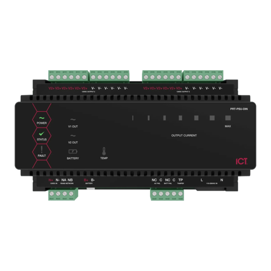
Page 24: Led Indicators
LED Indicators Protege DIN Rail modules feature comprehensive diagnostic indicators that can aid the installer in diagnosing faults and conditions. In some cases an indicator may have multiple meanings depending on the status indicator display at the time. Status Indicator The status indicator displays the module status. -
Page 25: Battery Indicator
Battery Indicator The Battery indicator shows the status of the backup battery. State Description (with mains power connected - power indicator on) Flashing (red) Backup battery is disconnected On (red) Backup battery failed its dynamic battery test On (green) Last backup battery dynamic test successful State Description (with mains power disconnected - power indicator off) Flashing (red) -
Page 26: Error Code Indication
Error Code Indication When the module attempts to register or communicate with the system controller a registration error can be generated indicating that it was not successful. Error Code Display The following table is only valid if the FAULT indicator is CONSTANTLY ON and the STATUS indicator is FLASHING RED. -
Page 27: Mechanical Diagram
Mechanical Diagram The mechanical diagram shown below outlines the essential details needed to help ensure the correct installation of the Power Supply. PRT-PSU-DIN-8A | Protege DIN Rail 8A Intelligent Power Supply | Installation Manual... -
Page 28: Mechanical Layout
Mechanical Layout The mechanical layout shown below outlines the essential details needed to help ensure the correct installation of the Power Supply. 156.8mm FRONT BACK 143.5m m 156.8m m PRT-PSU-DIN-8A | Protege DIN Rail 8A Intelligent Power Supply | Installation Manual... -
Page 29: Technical Specifications
Integrated Control Technology continually strives to increase the performance of its products. As a result these specifications may change without notice. We recommend consulting our website (www.ict.co) for the latest documentation and product information. -
Page 30: New Zealand And Australia
New Zealand and Australia General Product Statement The RCM compliance label indicates that the supplier of the device asserts that it complies with all applicable standards. PRT-PSU-DIN-8A | Protege DIN Rail 8A Intelligent Power Supply | Installation Manual... -
Page 31: European Standards
European Standards CE Statement Conforms where applicable to European Union (EU) Low Voltage Directive (LVD) 2014/35/EU, Electromagnetic Compatibility (EMC) Directive 2014/30/EU, Radio Equipment Directive (RED)2014/53/EU and RoHS Recast (RoHS2) Directive: 2011/65/EU + Amendment Directive (EU) 2015/863. This equipment complies with the rules, of the Official Journal of the European Union, for governing the Self Declaration of the CE Marking for the European Union as specified in the above directive(s). - Page 32 Contact discharges ± 6 kV, Air discharges to ± 8 kV Radiated electromagnetic fields (EN 50130-4 ed. 2, EN 61000-4-3 ed.3) Conducted disturbances induced by electromagnetic fields (EN 50130-4 ed. 2, EN 61000-4-6) Fast Transient bursts (EN 50130-4 ed. 2, EN 61000-4-4 ed.2) To the AC mains supply lines applied disturbance signal voltage level 2 kV both polarities for 1 minute.
-
Page 33: Fcc Compliance Statements
FCC Compliance Statements FCC Rules and Regulations CFR 47, Part 15, Class A This equipment complies with the limits for a Class A digital device, pursuant to Part 15 of the FCC rules. Operation is subject to the following two conditions: This device may not cause harmful interference. -
Page 34: Industry Canada Statement
Industry Canada Statement ICES-003 This is a Class A digital device that meets all requirements of the Canadian Interference Causing Equipment Regulations. CAN ICES-3 (A)/NMB-3 (A) PRT-PSU-DIN-8A | Protege DIN Rail 8A Intelligent Power Supply | Installation Manual... -
Page 35: Disclaimer And Warranty
Integrated Control Technology Ltd nor its employees shall be liable under any circumstances to any party in respect of decisions or actions they may make as a result of using this information. In accordance with the ICT policy of enhanced development, design and specifications are subject to change without notice. - Page 36 Disclaimer: Whilst every effort has been made to ensure accuracy in the representation of this product, neither Integrated Control Technology Ltd nor its employees shall be liable under any circumstances to any party in respect of decisions or actions they may make as a result of using this information. In accordance with the ICT policy of enhanced development, design and specifications are subject to change without notice.
Need help?
Do you have a question about the Protege PRT-PSU-DIN-8A and is the answer not in the manual?
Questions and answers