
Subscribe to Our Youtube Channel
Related Manuals for ICT ICT-2U4


Summary of Contents for ICT ICT-2U4
- Page 1 Innovative Circuit Technology Ltd. MPS Ultra DC Power System INSTRUCTION MANUAL 855-340-032 DC Power System Models: ICT-2U4 ICT-2U5 ICT-2U6 ICT-2U8...
- Page 2 WARNING Risk of serious personal injury or damage to equipment and property! Always observe the following: • Install and operate unit in a restricted access location. A restricted access area is an area to which access can be gained only by service personnel using a special tool, lock and key, or other means of security and which is controlled by the authority responsible for the location.
-
Page 3: Table Of Contents
Load Distribution (with optional Load Distribution Module) ................... 35 Alarms ................36 Communications ................ 45 Router Configuration ..............47 Text Message Notifications .......... 47 Troubleshooting Network Communications ............STATUS INDICATORS AND ALARMS ..............PRODUCT SPECIFICATIONS: ............... ICT LIMITED WARRANTY Innovative Circuit Technology Ltd. -
Page 4: Introduction
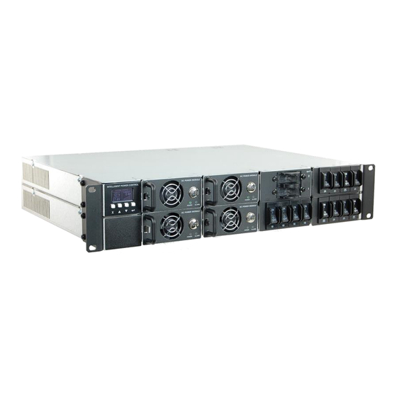
25.0 12.5 (+5%, -0%) A typical configuration is shown in Figure 1, consisting of an ICT-2U4 power chassis with Intelligent Control Module (ICM), four 700W Power Modules, Battery Management Module (BMMD) with two battery input breakers (battery 1 lower, battery 2 upper), and Load Distribution Module (LDM) (with output breakers 1 to 12). -
Page 5: Installation
Four bolt/washer/nut sets for connections to the bus bars (in bag) • Remote battery temperature sensor (ICT-TMP) • RJ-11 Parallel Control Cable jumper (ICT-JMP) System Model Numbers (Power Modules and load breakers must be ordered separately): Model No. Model No. - Page 6 Accepts up to six Power Modules for 4.2kW of output power. Intelligent Power Chassis with integrated Control Module and Ethernet ICT-2U8 (positive or negative Communications. Accepts up to eight output) Power Modules for 5.6kW of output power. Power Modules: (must be ordered separately) Description Model No.
- Page 7 (Figure 2). The system may remain powered while swapping modules. • Snap in blanking plate (ICT-BPM) if ordered into any unused Power Module positions to prevent accidental access to the internal circuitry of the system.
-
Page 8: Install Unit
Figure 2: Power Module Release Latch Install Unit WARNING Risk of serious personal injury or damage to equipment and property! Always observe the following! • When using a backup battery ensure the nominal battery voltage is correct for the model of Power Modules installed, and that the battery positive is connected to the positive (+) terminal and the battery negative is connected to the (-) terminal. - Page 9 Check that the default system output voltage and current limit match the requirements of the battery and the loads to be connected. Mount the unit in an enclosed standard 19 inch equipment rack or other restricted access location, using rack mounting screws (not supplied). Support the rear of the unit with rack supports or back rail if required.
- Page 10 Alarm output common Alarm Output Connector: (use 22-26AWG wire) • Connect the external Battery Temperature Sensor (ICT-TMP) to the REMOTE input plug on the back panel (see Remote input table, below), to compensate the system output voltage according to the battery temperature.
- Page 11 Make Battery Connections to BMMD The Battery Management Module (BMMD) provides a convenient and safe way to connect one or two external back-up batteries to the MPS Ultra system. Two high current hydraulic-magnetic circuit breakers (100A standard) provide over current protection, while an internal 150A LVD contactor will disconnect the battery string(s) should it discharge below a safe level.
- Page 12 terminal to the system “+” output, while “BAT –“ indicates a negative battery voltage system, with the LVD contactor and battery breaker internally connecting this terminal to the system “–“ output). Use wire and connectors appropriately rated for the highest possible system current when making connections to the battery, BMMD, and DC main outputs.
- Page 13 Power System (see the Network Monitoring and Control section for information on configuring and using the built in Web-GUI, e-mail, and SNMP functions). Install the provided Parallel Control Cable (ICT-JMP) between the two Share ports on the rear (figure 8).
-
Page 14: Operation (Front Panel)
Add an external breaker to the AC input to protect the MPS Ultra from inrush current as shown in the table below: Number of Power Recommended Breaker Rating (per shelf) Modules (single shelf) 100-120VAC Input 200-240VAC Input Two Power Modules Three Power Modules Four Power Modules Example: 3.5kW MPS Ultra at 240VAC input having 2 modules on the top shelf... -
Page 15: System Status
the current reading will flash to indicate when the unit is operating at its current limit. Up/Down Buttons: Use to scroll through display screens, and to adjust selected settings. Enter Button: Press to select a screen for adjustment, or to enter a new value after adjustment. - Page 16 • A small thermometer symbol to indicate that the remote temperature sensor is installed and may be compensating the output voltage • A bar graph indicating relative output current • Indication that the output has been Disabled (off) • Indication that a battery discharge test is in process System Settings: The output voltage and output current limit settings come with factory default values that should be adjusted to match your actual system and battery float voltage requirements, as shown below:...
-
Page 17: Battery Management Module
Once the output voltage and current limit values are configured to suit the connected battery and loads, switch on the BMM battery breaker 1, and battery breaker 2 (if installed) to connect the backup battery string(s) to the system. Switch on the LDM output breakers 1 to 4 (if installed) to energise any loads connected to the Distribution Module outputs. - Page 18 Set the Low SOC Alarm (%) if desired, to raise an alarm when the battery is nearly discharged. Ensure the Battery temperature sensor (ICT-TMP) is installed and connected to the battery case (see Make sensor and Alarm Connections in the Installation section) for optimal Lead-Acid battery charging and best battery life.
- Page 19 WARNING Use the Equalize Charge setting for flooded lead-acid batteries in a well- ventilated location only. Do not use Equalize Charge on sealed batteries! Configure the Battery Discharge Test to check on the battery’s ability to power the system for a set duration. Set Max Discharge Time, minimum Stop Voltage, and the automatic repeat Interval if desired.
-
Page 20: Load Distribution Module
Press Enter to select parameter to adjust Scroll to choose parameter in selected sub-menu. Press Enter to select that item for adjustment A notification will automatically appear indicating the results of a Discharge Test at completion of the test Load Distribution Module The Load Distribution Module (LDM) provides a convenient way to include up to twelve channels of remotely managed DC power distribution within the MPS Ultra system. -
Page 21: Alarm Inputs
Scroll to choose parameter or sub-menu. Press Enter to select that item for adjustment Press Enter to select setting to be changed Scroll to choose Output to be changed (On/Off control shown) Scroll to change setting. Press Enter set, press Back X button to exit without changing Alarm Inputs The Alarm Inputs Status screen displays the current status of the four alarm inputs... -
Page 22: Network Status And Advanced Options
Scroll through the history screens to see the 20 most recent Alarm events. Shows the Module that raised the alarm, date, and time when set, and cleared The system date and time are normally set by the network. These may be manually set, see Network GUI Operation, Communication Basic Setup section. -
Page 23: Operation (Network Gui)
You can also find the IP address of any ICT unit on a local network by running the ICT IP Address Discovery tool, after installing it on your Windows computer connected to the same network (tool available for download from ICT http://www.ict-power.com/tools-utilities/). -
Page 24: System
System The STATUS tab displays the current states and parameters of the system such as the output voltage and current, the AC input voltage, the optional battery management module parameters, the state and loading on the four optional load distribution module outputs, and the alarm states of the internal alarm relay and the four remote alarm inputs. -
Page 25: Power Modules
remotely force connected equipment to reboot. The DC output cannot be disabled during an AC failure. System Output Settings Output Settings Output Voltage: Enter the DC output voltage of the system to the voltage requirement of the load and/or battery. Current Limit: Enter the DC output current limit of the system to the max current requirement of the load and/or battery. -
Page 26: Battery Backup (With Optional Battery Management Module)
The STATUS tab displays the current state and parameters of the battery backup module such as battery string voltage, combined current (positive value for charging and negative value for discharging), temperature (if ICT-TMP probe is installed), Net Ah count (approximate Ah discharged from the battery, where 0Ah denotes full charge), LVD status, and the LVD threshold voltage settings. - Page 27 Configure Battery Battery Type: Configure the type of the battery used in the system (Lead- Acid or Lithium-Ion). WARNING Always consult battery manufacturer's specifications when selecting battery type. Incorrect battery type setting may damage your battery. If Lithium-Ion type battery is selected, it must utilize an integrated battery management system (BMS) to protect the battery cells from inappropriate voltage or current levels.
- Page 28 setting should be set to the value recommended by the battery manufacturer. LVD Settings Disconnect Voltage: Enter the battery low voltage disconnect voltage threshold to a level that will protect the battery from excessive discharge (default is 10.5/21/42V). The LVD contactor will open when the battery discharges to this level for at least 3s.
- Page 29 The system must have the battery temperature sensor (ICT-TMP) installed on the system and battery for this setting to have an effect. The 0mV setting (default) assumes 25°C operation. This setting is only available if the system is configured for use with a lead-acid type battery.
- Page 30 Manual Equalize Charge: Click this button to manually initiate an equalize charge for the set duration time once the battery is fully charged. System will state that “Manual Equalize Charge is Not Ready” if battery is not yet fully charged. Last Equalize Charge, Charge Time, Next Equalize Charge: The date and time of the last equalize charge and the duration of the charge are noted here along with the scheduled date and time of the next automatic equalize...
-
Page 31: Load Distribution (With Optional Load Distribution Module)
Discharge Test Interval: Enter the discharge test interval to have the system automatically initiate a discharge test every interval, once the battery reaches 100% SOC. Set this interval to 0 days to disable the automatic discharge test (default setting). Day of Week: Select the day of the week that the automatically recurring discharge test should take place, or select "Any"... - Page 32 Click on the SETTINGS & CONTROL tab (or MODULE #_ SETTINGS tab if more than one LDM module is installed) to configure all load distribution related settings. Click on the Save Settings button at the bottom of the page to store your changes. Module Control Module Output Control Output #_: Click the On or Off button to remotely enable or disable that...
- Page 33 Click the All Outputs ON or All Outputs OFF button to enable or disable all four output channels simultaneously. All outputs are enabled as the factory default setting. Any output channel that has the power cycling option enabled will go through the cycle when the All Outputs OFF button is clicked. Module Setup Power-On Sequencing / Power Cycling Delay Time: Enter a delay time to be used for the wait time before enabling...
- Page 34 Multiple outputs channels with power cycling enabled that are disabled will be re-enabled in sequence from output #1 to #4. This feature is useful for remotely resetting power to a router or other hardware required for the network connectivity of the panel. Output #_ Load-Shedding Enable Load-Shedding: Check this box to disable an output channel when the bus voltage drops below the load-shedding threshold for at least 30s.
-
Page 35: Alarms
to trigger the Under-Current Alarm. Disable this alarm by setting the threshold to 0A (default). Click the Save Settings button to save the configuration for that output channel, and then repeat the setup process for each of the 4 output channels to be used. Alarms The STATUS tab displays the current state and history of the alarms. -
Page 36: Communications
Send E-mail: Check this box to have an alarm e-mail sent to the e-mail address(es) set up in the Communications E-MAIL SETUP page. Communications Select the Communications page tab to configure the basic system parameters, network settings, e-mail settings, user setup, and maintenance functions. Click on the BASIC SETUP tab to configure the device name, set the date and time and enable the watchdog timer and data logging features. - Page 37 Watchdog Enabled: Check this box to enable the network watchdog to cycle power to an external device on loss of communication. Primary IP Address: Enter the primary IP address the unit will ping to determine the network is functioning. Secondary IP Address: Enter the secondary IP address the unit will ping to determine the network is functioning.
- Page 38 IP Address: Enter a unique IP address for the unit. Subnet Mask: Enter the mask for the subnet the panel is located on. Gateway: Enter the IP address of the default router (Gateway) used for connecting attached devices to different networks. Primary DNS: Enter the IP address of the Primary DNS Server for your network.
- Page 39 • Full Device Control: Allow SNMP clients to set all device settings through SNMP. MIB files for full SNMP device control can be downloaded from the ICT Website: https://www.ict-power.com/tools-utilities/ SNMP Contact Information: Enter contact information such as an operator name and phone number for the panel, which can be read via SNMP queries.
- Page 40 Read Community: Enter the community string/password here for read- only SNMP access. The default read community string is “public”. Write Community: Enter the community string/password here for read/write SNMP access. The default write community string is “write”. NOTE: The community strings should be changed to unique passwords before enabling SNMP, as the defaults are well known.
- Page 41 Privacy Protocol: Select the privacy protocol for SNMPv3 traps (None, or AES). Privacy Password: If a privacy protocol is selected, enter the privacy password for SNMPv3 traps. Trap IP Addresses: Enter the IP addresses for up to two devices that will receive SNMP traps from the panel.
- Page 42 Recipient E-mail Addresses: Enter one or more e-mail addresses that are to receive all e-mail notifications from the panel. Use commas to separate multiple addresses. This field can also be used to send a text message notification to a phone; see the Text Message Notifications section for further information.
- Page 43 Record your new password(s) for future access! If the Administrator password is lost the unit must be reset to return the password to the blank default setting, causing loss of all other user settings. See the Password Reset section for more details.
- Page 44 MPS you are logged in to, greatly simplifying the configuration of multiple identical units. Firmware Update: Download the latest MPS Ultra firmware file from the ICT website (ict-power.com) to your local computer. De-compress this .cry file then press the Update Firmware button, and link to this file.
-
Page 45: Router Configuration
Send Test E-mail: Click the Send Test E-mail button to send a test e-mail to the listed e-mail recipients using the e-mail settings on the E-mail Setup page. Ping Diagnostics Tool: Use this feature to verify connectivity of any network connected device. - Page 46 (Valid port numbers are in the range of 1 to 65535) See the Network Setup section for information on assigning new network ports. You must also change the panel’s HTTP port from 80 if your local network has another device (such as a panel, or web server) already using port 80. 3.
-
Page 47: Text Message Notifications
I am unable to access the web-based configuration utility: • Check that you are using the correct IP address for the system by downloading and running the ICT IP Address Discovery tool http://www.ict-power.com/tools-utilities/ • Check the network cable connections to the panel and the network... -
Page 48: Status Indicators And Alarms
• Ensure the network card settings on your computer are configured for accessing the IP address of the MPS. To access a panel with the default IP address of 192.168.0.180 the typical network settings for your computer are: IP Address: 192.168.0.180 Subnet Mask: 255.255.255.0 Gateway: 192.168.0.1 •... - Page 49 remotely monitored units. Green “POWER” and red “FAULT” LED’s on the power modules, along with the Form-C alarm contacts on the back panel indicate the core status of power system, even on non-ICM equipped units. There is an option on the Setup page in the GUI for most alarms to make a selection to have the system send an Email to designated addresses for remote notification.
- Page 50 Battery Management Module (BMMD) Alarms: Alarm Condition Trigger Condition Alarm Send Contactor Required Relay Email Module Power Loss of AC, and battery Open Failure disconnected No Alarms Normal Operation Closed Battery Low SOC SOC drops below Low Closed Active SOC setting Battery Battery I rises above OC Closed...
-
Page 51: Product Specifications
Alarm Condition Trigger Condition Alarm Relay Send Email System Overcurrent Total output current on Active System is >150Adc for 20s System Current ALL power modules in system Active Limit at their current or power limit for 15s Communication Bus Internal communication bus Active Error error condition... - Page 52 48V Module Power System Module Module BMMD Max total Battery 150A Current through LVD BMMD LVD Threshold V 11.5V 23.0V 46.0V (Default) BMM LVD Reconnect V 12.5V (Default setting) BMMD idle DC Power Draw <1W LDM Max Load per Output (continuous) Output Grounding: Power Modules are floating, may be...
- Page 53 • Consult the dealer or an experienced RF technician for help. Caution: Changes or modifications to this equipment not expressly approved by ICT Ltd. could void the user's authority to operate the equipment. Innovative Circuit Technology Ltd.
-
Page 54: Ict Limited Warranty
Warranty to such components or accessories. In no event shall ICT be liable for any special, indirect or consequential damages such as, but not limited to, loss of use, business or goodwill, loss of revenue, or loss of profits, which may result, either directly or indirectly, from defects in products provided by ICT.
Need help?
Do you have a question about the ICT-2U4 and is the answer not in the manual?
Questions and answers