
Related Manuals for ICT ICT690-12S


Summary of Contents for ICT ICT690-12S
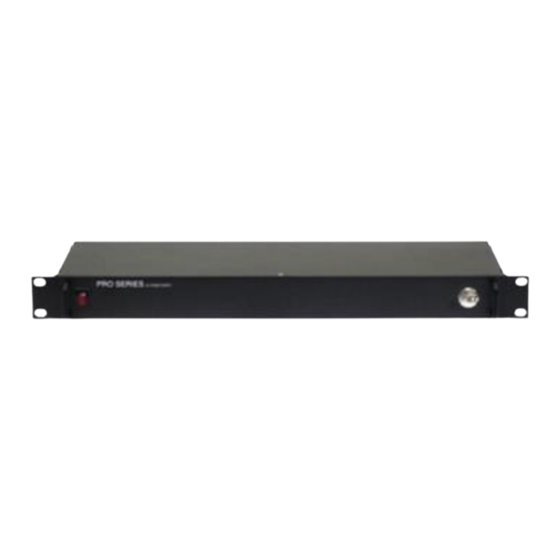
- Page 1 Pro Series DC Power Supply INSTRUCTION MANUAL 855-343-001 Models: ICT690-12S/ICT690-12SB ICT690-24S/ICT690-24SB ICT690-48S/ICT690-48SB ICT1190-12S/ICT1190-12SB ICT1190-24S/ICT1190-24SB ICT1190-48S/ICT1190-48SB “DC Power Solutions…not just components”...
- Page 2 WARNING Risk of serious personal injury or damage to equipment and property! Always observe the following: Install and operate unit in a Restricted Access location, such as an enclosed equipment rack Operate the supply from a grounded 3-pin 120Vac or 230Vac outlet (50 or 60Hz) with a branch circuit breaker rated 20A or less Always observe the following for applications requiring a back up battery: ...
-
Page 3: Table Of Contents
Table of Contents INTRODUCTION ................... 4 CHECK and CONFIGURE UNIT ..............4 INSTALLATION ..................... 6 OPERATION ....................7 Status Indicators and Alarms ..............9 PRODUCT SPECIFICATIONS ............... 10 LIMITED WARRANTY ................. 12 Innovative Circuit Technology Ltd. -
Page 4: Introduction
INTRODUCTION Pro Series power supplies from ICT provide a reliable 690 or 1200 Watts of rack- mountable dc power with optional built-in battery back-up support and a low voltage disconnect (LVD, option “B”) to power 12, 24, or 48Vdc based systems. - Page 5 WARNING Risk of serious personal injury or damage to equipment and property! Always observe the following! If a battery is used ensure the nominal battery voltage is correct for the model of power supply, and that the battery positive is connected to the BAT positive (+) terminal and the battery negative is connected to the NEG (-) terminal.
-
Page 6: Installation
Set the max charge current to be supplied to the battery by setting SW 3, and SW 4 on the back panel according to the following chart: (note that actual current flow to the battery may be less than the setting, and is determined by the battery state of charge and temperature) Charge Charge... -
Page 7: Operation
Connect the supply NEG bus bar to the load negative input terminal (using a supplied bus bar bolt/washer/nut set for the bus bar connection) Connect a ground bonding wire from the chassis ground stud to the rack On units with the optional battery back-up and LVD capability (model suffix “B”): Choose a lead-acid battery with a float voltage rating that matches the... - Page 8 digital voltmeter. If a battery is connected install the external fuse and close the disconnect switch. On units with the battery back-up option connected switch off the ac power, and use a hand held digital voltmeter to verify that the battery voltage is provided to the output load terminal.
-
Page 9: Status Indicators And Alarms
Status Indicators and Alarms The 2 LEDs on the front panel and the Form-C alarm contacts on the back indicate the status of the power supply: Alarm or Trigger Condition LOAD BATT Green Notification Output FAULT POWER Enabled Enabled Input AC OK, Normal operation, battery charging battery charging... -
Page 10: Product Specifications
PRODUCT SPECIFICATIONS AC Input (IEC C 14 connector): 110 to 254Vac 50/60Hz Input Power Factor: 0.99 typ (120Vac input) Peak Efficiency (typical): Output V Line Regulation: +/- 0.1% Output V Load Regulation: +/- 1% Model: 100A 12.5A Output Voltage (Nominal Battery float Voltage) (+/- 13.8V 13.8V... - Page 11 Alarm, on/off Connector: 5 pin removable plug, cage clamp type 16 –24 AWG Operating Temperature Range: -30C to +60°C Storage Temperature Range: -40 to +70°C Humidity: (Operating) 10 – 90% (non-condensing) (Storage) 5 – 95% (non-condensing) Cooling: Temperature controlled Regulatory Compliance: Designed to meet UL/CSA60950-1, Meets FCC Part 15 Class B limits...
-
Page 12: Limited Warranty
The user of ICT products, which are to be used in life support applications as described above, assumes all risks of such use and indemnifies ICT against all damages.
Need help?
Do you have a question about the ICT690-12S and is the answer not in the manual?
Questions and answers