
Related Manuals for GE Healthcare Optima XR200amx


Summary of Contents for GE Healthcare Optima XR200amx
- Page 1 Front cover GE Healthcare Optima XR200amx/XR220amx Installation Manual Direction 5336113-1EN Revision 10...
- Page 2 Warning GE H XR200 /XR220 EALTHCARE PTIMA 5336113-1EN R IRECTION EVISION NSTALLATION ANUAL ATTENTION LES APPAREILS A RAYONS X SONT DANGEREUX A LA FOIS POUR LE PATIENT ET POUR LE MANIPULATEUR SI LES MESURES DE PROTECTION NE SONT PAS STRICTEMENT APPLIQUEES Bien que cet appareil soit construit selon les normes de sécurité...
- Page 3 GE H XR200 /XR220 EALTHCARE PTIMA 5336113-1EN, R IRECTION EVISION NSTALLATION ANUAL Important information WARNING This service manual is available in English only. • If a customer's service provider requires a language other than English, it is the customer's (EN) responsibility to provide translation services.
- Page 4 σέρβις, στο χειριστή ή στον ασθενή από ηλεκτροπληξία, μηχανικούς ή άλλους κινδύνους. FIGYELMEZTETÉS Ezen karbantartási kézikönyv kizárólag angol nyelven érhető el. • Ha a vevő szolgáltatója angoltól eltérő nyelvre tart igényt, akkor a vevő felelőssége a fordítás (HU) elkészíttetése. •...
- Page 5 GE H XR200 /XR220 EALTHCARE PTIMA 5336113-1EN, R IRECTION EVISION NSTALLATION ANUAL AVVERTENZA Il presente manuale di manutenzione è disponibile soltanto in lingua inglese. • Se un addetto alla manutenzione richiede il manuale in una lingua diversa, il cliente è tenuto a (IT) provvedere direttamente alla traduzione.
- Page 6 GE H XR200 /XR220 EALTHCARE PTIMA 5336113-1EN, R IRECTION EVISION NSTALLATION ANUAL ATENŢIE Acest manual de service este disponibil doar în limba engleză. • Dacă un furnizor de servicii pentru clienţi necesită o altă limbă decât cea engleză, este de datoria (RO) clientului să...
- Page 7 Legal notes TRADEMARKS Optima XR200amx and Optima XR220amx are trademarks of GE Healthcare. WPA and WPA2 are trademarks of the Wi-Fi Alliance. All other products and their name brands are trademarks of their respective holders. COPYRIGHTS All material copyright © 2011 by General Electric Company, Inc. All rights reserved. The material presented and contained herein may not be reproduced in any form or manner, without the written permission of General Electric Company, Inc.
- Page 8 X-ray equipment if not properly used may cause injury. Accordingly, the instructions herein contained should be thoroughly read and understood by everyone who will use the equipment before you attempt to place this equipment in operation. GE Healthcare will be glad to assist and cooperate in placing this equipment in use.
- Page 9 GE Healthcare support documentation library. OMISSIONS AND ERRORS Customers, please contact your GE Healthcare sales or service representatives. GE personnel, please use the GE Healthcare complaint handling process to report all omissions, errors, and defects in this publication. Preface...
-
Page 10: Direction 5336113-1En, Revision
GE H XR200 /XR220 EALTHCARE PTIMA 5336113-1EN, R IRECTION EVISION NSTALLATION ANUAL Revision history Revision Date Reason for change 26SEP2011 Initial release of document. 26OCT2011 SPR HCSDM00103773 - Table 3-3 and Table 3-5 removing drive handle SPR HCSDM00103774 - DAP installation... - Page 11 GE H XR200 /XR220 EALTHCARE PTIMA 5336113-1EN, R IRECTION EVISION NSTALLATION ANUAL Revision Date Reason for change 03DEC2014 Chapter 2, Section 2.1, added Tablet holder assembly (optional, Optima XR220amx and Optima XR200amx) under “shipped with the Optima XR200amx/Optima XR220amx system”.
- Page 12 GE H XR200 /XR220 EALTHCARE PTIMA 5336113-1EN, R IRECTION EVISION NSTALLATION ANUAL Page 12 Preface...
- Page 13 Preface - Publica- GE H XR200 /XR220 EALTHCARE PTIMA 5336113-1EN, R IRECTION EVISION NSTALLATION ANUAL Preface Publication Conventions Standardized conventions for representing information is a uniform way of communicating information to a reader in a consistent manner. Conventions are used so that the reader can easily recognize the actions or decisions that must be made.
- Page 14 GE H XR200 /XR220 EALTHCARE PTIMA 5336113-1EN, R IRECTION EVISION NSTALLATION ANUAL • Destruction of a disk drive • Potential for internal mechanical damage, such as to a X-ray tube Symbols and Pictorials Used The following Symbols and Pictorials are be used in this publication. These graphical icons (symbols) may be used to make you aware of specific types of hazards that could possibly cause harm.
- Page 15 GE H XR200 /XR220 EALTHCARE PTIMA 5336113-1EN, R IRECTION EVISION NSTALLATION ANUAL Publication Conventions General Paragraph and Character Styles Prefixes are used to highlight important non-safety related information. Paragraph prefixes (such as Purpose, Example, Comment or Note) are used to identify important but non-safety related information.
- Page 16 GE H XR200 /XR220 EALTHCARE PTIMA 5336113-1EN, R IRECTION EVISION NSTALLATION ANUAL Computer Screen Output/Input Text Character Styles Within this publication, mono-spaced character styles (fonts) are used to indicate computer text that’s either screen input and output. Mono-spaced fonts, such courier, are used to indicated text direction.
-
Page 17: Table Of Contents
GE H XR200 /XR220 EALTHCARE PTIMA 5336113-1EN, R IRECTION EVISION NSTALLATION ANUAL Table of contents Chapter 1 Safety....................21 Section 1.1 Energy sources................21 Section 1.2 Lock Out/Tag Out (LOTO) procedure for electrical power ..22 1.2.1 Preparing for LOTO....................22 1.2.2... - Page 18 GE H XR200 /XR220 EALTHCARE PTIMA 5336113-1EN, R IRECTION EVISION NSTALLATION ANUAL 3.6.6 Detector registration ....................54 3.6.7 Applying detector identification shapes ..............54 3.6.8 Installing the detector grid..................55 3.6.8.1 Unpacking and inspecting the grid ..............55 3.6.8.2 Grid handling ....................55 3.6.8.3...
- Page 19 GE H XR200 /XR220 EALTHCARE PTIMA 5336113-1EN, R IRECTION EVISION NSTALLATION ANUAL Section 4.10 Installing hardware options ............74 4.10.1 Installing the barcode reader ..................74 4.10.1.1 Installing the barcode reader receiver ............. 74 4.10.1.2 Connecting the barcode reader ............... 77 4.10.1.3 Barcode reader LED indicators ...............
- Page 20 GE H XR200 /XR220 EALTHCARE PTIMA 5336113-1EN, R IRECTION EVISION NSTALLATION ANUAL Chapter 6 Detector checks and QAP ............119 6.0.1 Detector check......................119 6.0.2 QAP checkout......................119 Chapter 7 Certified components ..............121 Section 7.1 Component rating plates............121 Chapter 8 Final tasks..................
-
Page 21: Chapter 1 Safety
GE H XR200 /XR220 EALTHCARE PTIMA 5336113-1EN, R IRECTION EVISION NSTALLATION ANUAL Chapter 1 Safety Section 1.1 Energy sources Table 1-1 Energy source Yes/No Location of energy Magnitude of energy isolating means Electrical AC power plug 120 VAC/60Hz 220 VAC/50Hz... -
Page 22: Section 1.2 Lock Out/Tag Out (Loto) Procedure For Electrical Power
GE H XR200 /XR220 EALTHCARE PTIMA 5336113-1EN, R IRECTION EVISION NSTALLATION ANUAL Section 1.2 Lock Out/Tag Out (LOTO) procedure for electrical power Name of equipment: Optima XR200amx/Optima XR220amx Number of locks: 3 Title of employees authorized to perform LOTO: Those trained in LOTO Title of affected employees and how to notify: Hospital personnel, notified by verbal communication 1.2.1 Preparing for LOTO... - Page 23 GE H XR200 /XR220 EALTHCARE PTIMA 5336113-1EN, R IRECTION EVISION NSTALLATION ANUAL Locate the AC power plug (E1), system circuit breaker (E2), and battery connectors (E3). See Figure 1-2. Figure 1-2 Electrical energy lockout locations Chapter 1 Safety Page 23...
-
Page 24: Performing Loto
GE H XR200 /XR220 EALTHCARE PTIMA 5336113-1EN, R IRECTION EVISION NSTALLATION ANUAL 1.2.2 Performing LOTO Notify all affected personnel working in the area that LOTO is being performed. Exit all system software. Turn off the Optima XR200amx/Optima XR220amx system by pressing the power button and holding it for several seconds until the power button light ring turns blue, indicating that the system is shutting down. - Page 25 GE H XR200 /XR220 EALTHCARE PTIMA 5336113-1EN, R IRECTION EVISION NSTALLATION ANUAL Disconnect the two green battery power connectors J3 and J4 and the two sense connectors J13 and J14 from the Cricket board. Apply a locking device, then apply your personal red lock and tag.
- Page 26 GE H XR200 /XR220 EALTHCARE PTIMA 5336113-1EN, R IRECTION EVISION NSTALLATION ANUAL Disconnect the two green battery power connectors J1 and J2 and the two sense connectors J11 and J12 from the Cricket board. Apply a locking device, then apply your personal red lock and tag.
-
Page 27: Returning System To Service
GE H XR200 /XR220 EALTHCARE PTIMA 5336113-1EN, R IRECTION EVISION NSTALLATION ANUAL Figure 1-7. Verify that electrical power has been removed from the system by applying the DC voltmeter (+) lead to connector J5 pin 1 (Item 1, left-side screw terminal) on the Cricket board and the meter (-) lead to chassis ground (Item 2). -
Page 28: Section 1.3 Electrostatic Discharge (Esd)
GE H XR200 /XR220 EALTHCARE PTIMA 5336113-1EN, R IRECTION EVISION NSTALLATION ANUAL Re-energize equipment and follow safe startup procedures. Notify affected persons that energy has been restored. Section 1.3 Electrostatic discharge (ESD) A sudden discharge of static electricity from your finger or other conductor can destroy static sensitive devices or microcircuitry. -
Page 29: Personal Grounding Methods And Equipment
GE H XR200 /XR220 EALTHCARE PTIMA 5336113-1EN, R IRECTION EVISION NSTALLATION ANUAL • Protect all electrostatic parts and assemblies with conductive or approved containers or packaging. • Keep electrostatic sensitive parts in their containers until they arrive at static-free stations. -
Page 30: Recommended Materials And Equipment
GE H XR200 /XR220 EALTHCARE PTIMA 5336113-1EN, R IRECTION EVISION NSTALLATION ANUAL • Cover the work surface with approved static-dissipative material. Provide a wrist strap connected to the work surface and properly grounded tools and equipment. • Use static-dissipative mats, foot straps, or air ionizers to give added protection. -
Page 31: Chapter 2 System Overview
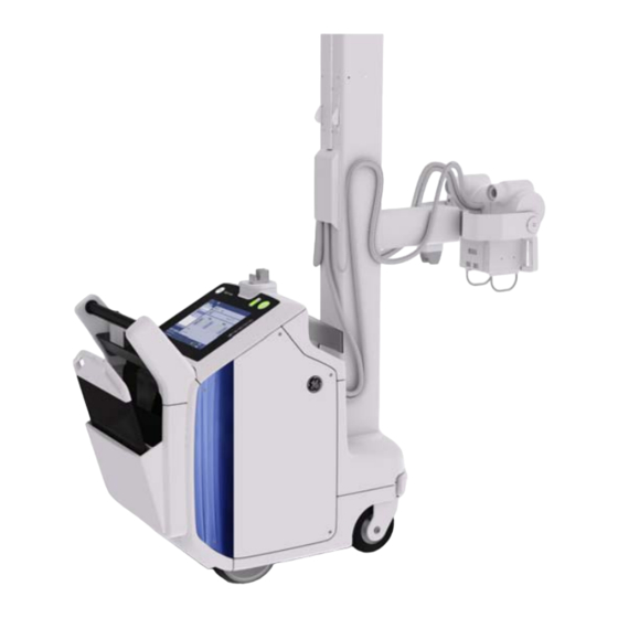
GE H XR200 /XR220 EALTHCARE PTIMA 5336113-1EN, R IRECTION EVISION NSTALLATION ANUAL Chapter 2 System overview Section 2.1 System components Available components of the Optima XR200amx/Optima XR220amx system are listed below. Shipped with the Optima XR200amx/Optima XR220amx system: • Optima XR200amx/Optima XR220amx •... - Page 32 GE H XR200 /XR220 EALTHCARE PTIMA 5336113-1EN, R IRECTION EVISION NSTALLATION ANUAL Optima XR200amx Optima XR220amx Figure 2-1 Optima systems Page 32 Section 2.1 System components...
-
Page 33: Chapter 3 Installation
GE H XR200 /XR220 EALTHCARE PTIMA 5336113-1EN, R IRECTION EVISION NSTALLATION ANUAL Chapter 3 Installation Section 3.1 Installation process Unpack the system (Section 3.2 Unpacking the system on page 34). Replace the electrical plug, if necessary (Section 3.3 Replacing the electrical plug on page 35). -
Page 34: Section 3.2 Unpacking The System
GE H XR200 /XR220 EALTHCARE PTIMA 5336113-1EN, R IRECTION EVISION NSTALLATION ANUAL YSTEM NSTALLATION ORKFLOW Does the Upack Replace the power plug meet the system power plug requirements? Perform ground and leakage testing Is the Plug in and system an... -
Page 35: Section 3.3 Replacing The Electrical Plug
If no damage is observed, continue with the installation. If damage is found, contact GE Service or the installation specialist. Section 3.3 Replacing the electrical plug In regions that use an electrical plug other than the style used in the United States, remove the electrical plug and replace it with the appropriate hospital-grade plug as dictated by local regulations. - Page 36 GE H XR200 /XR220 EALTHCARE PTIMA 5336113-1EN, R IRECTION EVISION NSTALLATION ANUAL If the circuit breaker is OFF, flip it to the ON position. Item Description ON position OFF position Trip lever Figure 3-2 Circuit breaker in ON position Press and release the power button to turn on the Optima XR200amx/XR220amx system.
-
Page 37: Section 3.5 Ground And Leakage Testing
GE H XR200 /XR220 EALTHCARE PTIMA 5336113-1EN, R IRECTION EVISION NSTALLATION ANUAL Section 3.5 Ground and leakage testing Perform ground resistance testing & leakage testing only in the cases outlined in Table 3-1. Site location Perform ground testing? Perform leakage testing? -
Page 38: Attaching Test Cables
GE H XR200 /XR220 EALTHCARE PTIMA 5336113-1EN, R IRECTION EVISION NSTALLATION ANUAL Figure 3-5 Lug and clamp on ground wire 3.5.1.2 Attaching test cables On the tester, loosen both the current output (Source) terminal knob (top right) and the voltage measurement (Sense) terminal knob (bottom right) by turning them counterclockwise. - Page 39 GE H XR200 /XR220 EALTHCARE PTIMA 5336113-1EN, R IRECTION EVISION NSTALLATION ANUAL Figure 3-7 Cable A, Cable B, and short bar connections Chapter 3 Installation Page 39...
-
Page 40: Setting Test Parameters
GE H XR200 /XR220 EALTHCARE PTIMA 5336113-1EN, R IRECTION EVISION NSTALLATION ANUAL 3.5.1.3 Setting test parameters Turn on the tester by pressing the POWER button. The tester enters the ready state five seconds after startup (the model name and version display during startup). -
Page 41: Performing Zero Adjustment
GE H XR200 /XR220 EALTHCARE PTIMA 5336113-1EN, R IRECTION EVISION NSTALLATION ANUAL Figure 3-9 Current setting on the tester 3.5.1.4 Performing zero adjustment Ground measurements may be affected by a voltage drop in the A and B cables. To account for the voltage drop, perform the zero adjustment procedure before taking ground measurements. - Page 42 GE H XR200 /XR220 EALTHCARE PTIMA 5336113-1EN, R IRECTION EVISION NSTALLATION ANUAL Figure 3-11 Tester during and after zero adjustment Page 42 Section 3.5 Ground and leakage testing...
-
Page 43: Taking Ground Measurements
GE H XR200 /XR220 EALTHCARE PTIMA 5336113-1EN, R IRECTION EVISION NSTALLATION ANUAL 3.5.1.5 Taking ground measurements Turn off system power and main circuit breaker. Connect cable A to the grounding pin on the electrical plug. Connect cable B to the first measurement point listed in Table 3-3. - Page 44 GE H XR200 /XR220 EALTHCARE PTIMA 5336113-1EN, R IRECTION EVISION NSTALLATION ANUAL Figure 3-12 Tube test points Figure 3-13 Collimator test points Page 44 Section 3.5 Ground and leakage testing...
- Page 45 GE H XR200 /XR220 EALTHCARE PTIMA 5336113-1EN, R IRECTION EVISION NSTALLATION ANUAL Figure 3-14 Column test point Figure 3-15 Rear bin accessory access cover test point Chapter 3 Installation Page 45...
- Page 46 GE H XR200 /XR220 EALTHCARE PTIMA 5336113-1EN, R IRECTION EVISION NSTALLATION ANUAL Figure 3-16 Tube latch test point Page 46 Section 3.5 Ground and leakage testing...
-
Page 47: Performing Leakage Current Testing
GE H XR200 /XR220 EALTHCARE PTIMA 5336113-1EN, R IRECTION EVISION NSTALLATION ANUAL 3.5.2 Performing leakage current testing If ground testing is required for this system, verify that the ground testing results (see Table 3-3) are < 0.1 Ohms before conducting leakage testing. -
Page 48: Condition 1: Power Off, Normal Outlet, X-Ray Off
GE H XR200 /XR220 EALTHCARE PTIMA 5336113-1EN, R IRECTION EVISION NSTALLATION ANUAL Potential test equipment damage. Always pause in the OFF position when moving the OUTLET switch from NORMAL to REVERSED or REVERSED to NORMAL. Failure to do so can result in the internal test meter failure and tripping of facilities circuit breakers. -
Page 49: Condition 2: Power Off, Reversed Outlet, X-Ray Off
GE H XR200 /XR220 EALTHCARE PTIMA 5336113-1EN, R IRECTION EVISION NSTALLATION ANUAL Insert the black coil cord with clamp into the CHASSIS connection located on the top of the test meter (Figure 3-18). Figure 3-18 Dale 601 meter, top view Connect the Dale 601 test meter to a wall outlet. -
Page 50: Condition 3: Power On, Normal Outlet, X-Ray Off
GE H XR200 /XR220 EALTHCARE PTIMA 5336113-1EN, R IRECTION EVISION NSTALLATION ANUAL 3.5.2.3 Condition 3: Power on, normal outlet, X-ray off Turn on the system power. On the test meter, set the Outlet switch to Normal. Using the clamp, connect to all conductive surfaces. -
Page 51: Unpacking The Detector
GE H XR200 /XR220 EALTHCARE PTIMA 5336113-1EN, R IRECTION EVISION NSTALLATION ANUAL The detector also has a backup tether that can be attached, if needed, to provide input power and wired communication. The backup tether must be attached to the detector to register the detector with the system, and can then be removed and stored. -
Page 52: Inspecting The Detector
If no damage is observed, proceed to the next step. • If damage is found, contact GE Service. 3.6.3 Charging the detector battery For all customers that do not support the USA style wall plugs, locally obtain and install a computer style power cord with a CE approved, IEC 60320-1 C13 style connector on one end and the locally appropriate wall plug connector on the other. -
Page 53: Connecting The Backup Tether
GE H XR200 /XR220 EALTHCARE PTIMA 5336113-1EN, R IRECTION EVISION NSTALLATION ANUAL Battery LED status Meaning Green, green Battery more than 75% remaining Off, green Battery remaining between 25% and 75% Off, yellow Battery remaining between 10% and 25% Off, red... -
Page 54: Download Detector Firmware
GE H XR200 /XR220 EALTHCARE PTIMA 5336113-1EN, R IRECTION EVISION NSTALLATION ANUAL The tether connector will only fit one way, as shown. 3.6.5 Download detector firmware This section applies to Optima XR200amx with digital upgrade and Optima XR220amx systems only. -
Page 55: Installing The Detector Grid
GE H XR200 /XR220 EALTHCARE PTIMA 5336113-1EN, R IRECTION EVISION NSTALLATION ANUAL • To remove, use a small flat-blade screwdriver. Insert the screwdriver tip under the slot in the side of the tag, and pry until the tag pops out. -
Page 56: Installing The Grid
GE H XR200 /XR220 EALTHCARE PTIMA 5336113-1EN, R IRECTION EVISION NSTALLATION ANUAL 3.6.8.3 Installing the grid Pinch Hazard Attach the grid holder according to Figure 3-24, being careful not to pinch fingers or clothing. The grid clips onto the detector. Make sure you attach it to the imaging side of the detector. -
Page 57: Chapter 4 Configuration
If system backups are lost or missing. If the software is re-installed but system configuration files are not restored, configure the system again. GE service may need to be contacted to enable purchased options. A software install resets all configuration data. If the system configuration files are restored, you do not need to re-configure the system. -
Page 58: Site Configuration
System ID This field is a GE proprietary field and cannot be used for any purpose other than the System ID. Violation of this mandate will result in Insite and/or other features not working. Customer IT personnel need to use other means for DICOM filtering on their DICOM machines. -
Page 59: Networking Configuration
GE H XR200 /XR220 EALTHCARE PTIMA 5336113-1EN, R IRECTION EVISION NSTALLATION ANUAL 4.2.2 Networking configuration The following information can be viewed regardless of service mode. Table 4-3 Networking tab parameters Parameter Definition Options: DHCP or Static. Determines whether the IP address is assigned, or acquired DHCP Configuration dynamically. -
Page 60: Hardware Configuration
QAP test should be XR200amx with digital performed. upgrade) Editable by GE Healthcare personnel only. VA Site Applies to USA Veterans Affairs facilities. Yes or No. Period of inactivity (no user input or processing activity) after which Screen Blank Timeout the screen will go blank, in minutes. -
Page 61: Wireless Configuration
GE H XR200 /XR220 EALTHCARE PTIMA 5336113-1EN, R IRECTION EVISION NSTALLATION ANUAL 4.2.6 Wireless configuration Before configuring the wireless settings, verify that the Wireless Hospital Network option is enabled on the Options screen (see 4.2.7 Options configuration on page 64). If the site doesn’t require for authentication certificates and keys, go directly to 4.2.6.2 Configuring broadcast SSID networks... -
Page 62: Configuring Non-Broadcast Ssid Networks
GE H XR200 /XR220 EALTHCARE PTIMA 5336113-1EN, R IRECTION EVISION NSTALLATION ANUAL Table 4-7 Authentication type Required fields No FIPS FIPS ON • Encryption (if different than TKIP) • Identity • Password • Client certificate -Enterprise (EAP) • Inner Auth •... -
Page 63: Troubleshooting Connections
GE H XR200 /XR220 EALTHCARE PTIMA 5336113-1EN, R IRECTION EVISION NSTALLATION ANUAL Some fields are auto-populated. Depending on the type of authentication, complete the other required information, as described in the table below: Table 4-8 Authentication type Required fields No FIPS... -
Page 64: Options Configuration
4.2.7 Options configuration The Optima XR200amx/XR220amx systems are delivered with a base set of operating software that is configured for immediate operation. Optional software and hardware purchased by the site must be enabled by GE Healthcare service personnel, such as: •... -
Page 65: Pnf Tabs And Parameters
GE H XR200 /XR220 EALTHCARE PTIMA 5336113-1EN, R IRECTION EVISION NSTALLATION ANUAL 4.2.9.2 PNF tabs and parameters Table 4-10 PNF parameters Option Description Named Services tab Used to set up filters to allow traffic to common network services (such as telnet or ftp) by name, without needing to know the port and protocol. -
Page 66: Time Server Configuration
(TCP, UDP, Any). Select ADD FILTER to apply your changes. GE Service tab Used to set IIP node-lock IP address and DICOM port. This page is limited to GE service personnel. 4.2.10 Time Server configuration Contact a GE service representative to configure Time Server settings. -
Page 67: Section 4.3 Changing Auto Protocol Assist Settings
Display the raw data file to the user. Section 4.3 Changing Auto Protocol Assist settings Contact a GE service representative to change Auto Protocol Assist settings. Section 4.4 DICOM connectivity configuration Follow the procedures in this section to configure DICOM connectivity to network hosts and printers. - Page 68 GE H XR200 /XR220 EALTHCARE PTIMA 5336113-1EN, R IRECTION EVISION NSTALLATION ANUAL On the Add Network Host window, on the Host tab, enter the appropriate values in the fields listed below. Some fields are available only on the Optima XR220amx or Optima XR200amx with digital upgrade system.
-
Page 69: Performing A C-Echo Test
GE H XR200 /XR220 EALTHCARE PTIMA 5336113-1EN, R IRECTION EVISION NSTALLATION ANUAL Table 4-13 Add Network Host – Preferences tab description Function Description Available only on the Optima XR220amx or Optima Allow this network host to send images XR200amx with digital upgrade system. -
Page 70: Removing Network Hosts
GE H XR200 /XR220 EALTHCARE PTIMA 5336113-1EN, R IRECTION EVISION NSTALLATION ANUAL On the Applications desktop, press the UTILITIES button. On the Utilities desktop, next to Network Connections, press EDIT. On the Network Connections window, in the Network Hosts section, select the network host connection to test, and press C-ECHO TEST. - Page 71 GE H XR200 /XR220 EALTHCARE PTIMA 5336113-1EN, R IRECTION EVISION NSTALLATION ANUAL For suggested parameter values for specific printer brands and models, refer to the System Manual, Appendix A Printer configuration. Table 4-14 Add Printer screen parameter descriptions Attribute Value...
-
Page 72: Removing Printers
Administrative users can enable or disable EMI reduction using the UTILITIES > PREFERENCES > IMAGE PROCESSING screen. Contact a GE service representative to configure EMI reduction factors. Page 72 Section 4.5 Image management... -
Page 73: Section 4.7 Loading Demo Images
GE H XR200 /XR220 EALTHCARE PTIMA 5336113-1EN, R IRECTION EVISION NSTALLATION ANUAL Section 4.7 Loading demo images Load demo images from the CD-ROM provided with the system into the image database. This is applicable only to Optima XR220amx or Optima XR200amx with digital upgrade systems. -
Page 74: Section 4.9 Login And User Management
CTRL+ALT+F7 Section 4.9 Login and user management GE service engineers must create a specified Account and Password for system administrator. System administrators can perform a number of tasks that affect what users can do or will see. The administrative options are described in the Optima XR200amx or Optima XR220amx Operator Manual, Appendix A Login Administration. - Page 75 GE H XR200 /XR220 EALTHCARE PTIMA 5336113-1EN, R IRECTION EVISION NSTALLATION ANUAL Figure 4-1 Sample barcode label Remove the system side covers and the top cover. See the System manual, Replacement Procedures, Top cover removal. Remove the two screws from the inside of the left drive handle support, then remove the cover.
- Page 76 GE H XR200 /XR220 EALTHCARE PTIMA 5336113-1EN, R IRECTION EVISION NSTALLATION ANUAL Cable access hole Figure 4-3 Cable access hole and receiver placement on system Attach the USB receiver to the plastic clip with the barcode facing out as shown in Figure 4-3.
-
Page 77: Connecting The Barcode Reader
GE H XR200 /XR220 EALTHCARE PTIMA 5336113-1EN, R IRECTION EVISION NSTALLATION ANUAL Item Description Host PC Detector power supply (Optima XR220amx and Optima XR200amx with digital upgrade only) Figure 4-4 Connect USB cable to PC The Windows standard device driver will be installed automatically when you connect the barcode reader receiver to the USB port and the system is powered up. -
Page 78: Configuring The Barcode Reader
GE H XR200 /XR220 EALTHCARE PTIMA 5336113-1EN, R IRECTION EVISION NSTALLATION ANUAL Figure 4-5 OPI-4002 barcode reader charging cradle and power adapters 4.10.2 Configuring the barcode reader Applies to Optima XR220amx or Optima XR200 with digital upgrade systems only The following section provides instructions for the default configuration and two optional settings. -
Page 79: Verifying The Default Configuration
GE H XR200 /XR220 EALTHCARE PTIMA 5336113-1EN, R IRECTION EVISION NSTALLATION ANUAL 4.10.2.2 Verifying the default configuration Turn on the system. Wait until the login screen appears. Verify that a green LED is blinking on the barcode reader receiver. Scan any barcode. -
Page 80: Optional Configuration 2
GE H XR200 /XR220 EALTHCARE PTIMA 5336113-1EN, R IRECTION EVISION NSTALLATION ANUAL 4.10.2.5 Optional configuration 2 Optional configuration 2 is to strip first two and last four characters, and add a Tab suffix. This configuration sets the barcode reader to strip the first two and last four characters, and add a Tab at the end of the scan. -
Page 81: Dap Installation For Optima Xr200Amx System
GE H XR200 /XR220 EALTHCARE PTIMA 5336113-1EN, R IRECTION EVISION NSTALLATION ANUAL Figure 4-9 DAP meter cable attached For Optima XR220amx systems, the DAP meter option is a standard option and has already been enabled. It can be turned on/off at the Applications level. - Page 82 GE H XR200 /XR220 EALTHCARE PTIMA 5336113-1EN, R IRECTION EVISION NSTALLATION ANUAL Connect the round cable connector to the DAP meter. See Figure 4-10. Figure 4-10 DAP meter cable attached Route the long DAP cable through the cable drape along the horizontal arm and vertical column.
- Page 83 GE H XR200 /XR220 EALTHCARE PTIMA 5336113-1EN, R IRECTION EVISION NSTALLATION ANUAL Figure 4-12 HV cable clamp Plug the other end of the DAP cable into the J6 bulkhead connector. See Figure 4-13. Install cable ties as necessary to secure cable within the bulkhead area.
- Page 84 GE H XR200 /XR220 EALTHCARE PTIMA 5336113-1EN, R IRECTION EVISION NSTALLATION ANUAL 10. Mount the clamp to the Thorax chassis. Slide the clamp to the rear of the mounting screw slots. 11. Tighten the clamp around the cable bundle, ensuring that the cables are not pinched by the clamp.
-
Page 85: Installing The Tablet Holder Assembly
DAP Calibration section, for calibration procedure. 4.10.4 Installing the tablet holder assembly When the tablet holder is on hand, contact a GE service representative to install the tablet holder assembly. Shut down the system and turn off the main circuit breaker. - Page 86 GE H XR200 /XR220 EALTHCARE PTIMA 5336113-1EN, R IRECTION EVISION NSTALLATION ANUAL holder assembly on the column.Apply thread locker (i.e. Loctite 243 ) to the 4 tablet holder assembly mounting screws (new item 1), and tighten the screws. Torque to 3.2 N-m (2.36 lbft).
- Page 87 GE H XR200 /XR220 EALTHCARE PTIMA 5336113-1EN, R IRECTION EVISION NSTALLATION ANUAL Put the tablet on the tablet holder and make sure the tablet is clamped well. After you turn the key to lock the clamp, please check the back of the tablet clamp assembly to make sure the tablet is well fixed by the clamp without any possibility to fall down from the holder.
- Page 88 GE H XR200 /XR220 EALTHCARE PTIMA 5336113-1EN, R IRECTION EVISION NSTALLATION ANUAL Lock Tablet Tablet holder assembly functional check. Tilt the tablet holder from 10° to -10°. Rotate the tablet holder from 0° to 90° Pull the handle on the tablet holder assembly to relax it from the column.
-
Page 89: Installing The Wireless Exposure Handswitch
10. Hand over the keys to site administrator. 4.10.5 Installing the wireless exposure handswitch Contact a GE service representative to install the wireless handswitch. Leave the wired handswitch on the system as a backup. Remove both side covers and the top cover. See System manual 5336122-1EN, Chapter 8, Section 8.1.2 - Top cover removal. - Page 90 GE H XR200 /XR220 EALTHCARE PTIMA 5336113-1EN, R IRECTION EVISION NSTALLATION ANUAL Table 4-16 Wireless handswitch kit 5503600 Part Number Description 5497064 Self-tapping Screw, KA35 X 10mm, Phillips Pan Head (not shown) 5497362 Drill Bit, 0.5 inch with 0.375 inch shank (not shown)
- Page 91 GE H XR200 /XR220 EALTHCARE PTIMA 5336113-1EN, R IRECTION EVISION NSTALLATION ANUAL Figure 4-17 Receiver mount Remove the existing nut and washer located behind where the PCB Module is to be placed, then attach the ground wire from the PCB Module to the system chassis stud and re-install the washer and nut.
- Page 92 GE H XR200 /XR220 EALTHCARE PTIMA 5336113-1EN, R IRECTION EVISION NSTALLATION ANUAL Mount the PCB Module in the bottom of the Thorax as shown below (Figure 4-19) by removing the adhesive liner and applying pressure to activate the adhesive. Figure 4-19 Mount PCB module in bottom of Thorax Route the cable attached to the PCB Module up along the main cable bundle between the Spyder and Locust boards.
- Page 93 GE H XR200 /XR220 EALTHCARE PTIMA 5336113-1EN, R IRECTION EVISION NSTALLATION ANUAL Disconnect the J5 plug from the Spyder board and plug into End C of the main cable from the PCB Module. Plug End B of the main cable into Spyder J5.
- Page 94 GE H XR200 /XR220 EALTHCARE PTIMA 5336113-1EN, R IRECTION EVISION NSTALLATION ANUAL Continue routing the main cable (twisted black and red wires) up through the Thorax (Figure 4- 23) to the LVLE2 and plug End A of the main cable into J6 on the LVLE2 (Figure 4-24).
- Page 95 GE H XR200 /XR220 EALTHCARE PTIMA 5336113-1EN, R IRECTION EVISION NSTALLATION ANUAL Position the Receiver Mount on the top cover. The mount is curved and will fit the contour of the top cover when it is located in the proper position. See...
- Page 96 GE H XR200 /XR220 EALTHCARE PTIMA 5336113-1EN, R IRECTION EVISION NSTALLATION ANUAL Figure 4-27 Drill holes 12. Temporarily remove the two nylon nuts from the standoffs on the Receiver. Run the cable of the Receiver through the ½" diameter hole in the Receiver Mount, then place the Receiver onto the Receiver Mount and reinstall the nylon nuts to secure it to the mount.
- Page 97 GE H XR200 /XR220 EALTHCARE PTIMA 5336113-1EN, R IRECTION EVISION NSTALLATION ANUAL 15. Attach the Receiver/Mount assembly to the top cover using the 3 self-tapping screws provided in the kit. See Figure 4-30. Do not over-tighten the screws. Figure 4-30 Attach Receiver/Mount assembly to top cover 16.
- Page 98 GE H XR200 /XR220 EALTHCARE PTIMA 5336113-1EN, R IRECTION EVISION NSTALLATION ANUAL 17. Continue routing the cable along the side of the PC and down through the hole in the sheet metal of the Thorax and between the Locust and Spyder boards. Plug the cable into the connector on the PCB Module.
-
Page 99: Section 4.11 Importing Custom Ip Looks From Definium Amx 700
GE H XR200 /XR220 EALTHCARE PTIMA 5336113-1EN, R IRECTION EVISION NSTALLATION ANUAL Apply the rating plate label to front cover, next to the power cord area. See Figure 4-33. Figure 4-33 Apply rating plate Fill out and submit the product locator card(s). -
Page 100: Section 4.12 Enabling Advanced Service Mode
Section 4.12 Enabling Advanced Service mode Advanced Service (sometimes called “in-house service” or “extended service”) is available to customers that have purchased an Advanced Service package license from GE Healthcare. Contact a GE service representative to enable Advanced Service. Advanced Service provides the following functionality: •... -
Page 101: Snapshot Tool Configuration
GE H XR200 /XR220 EALTHCARE PTIMA 5336113-1EN, R IRECTION EVISION NSTALLATION ANUAL instructions to change the default internal IP Address if an IP Address conflict occurs with the hospital network. Note: To change IP address or configure the snapshot tool, you need the Account and Password information. - Page 102 GE H XR200 /XR220 EALTHCARE PTIMA 5336113-1EN, R IRECTION EVISION NSTALLATION ANUAL #superxr Open Firefox Browser by typing the following command : firefox http://localhost/snapshot/Manual_Snapshot.html Click on SNAPSHOT PREFERENCES. See Figure 4-34. Figure 4-34 Snapshot Preferences Repeat Steps 6 through 17 (below) for the following four Configurations (available under the...
- Page 103 GE H XR200 /XR220 EALTHCARE PTIMA 5336113-1EN, R IRECTION EVISION NSTALLATION ANUAL In the Configuration drop-down menu, select ASNAPSHOT_LIGHTNING. See Figure 4-35. Figure 4-35 Select Configuration Chapter 4 Configuration Page 103...
- Page 104 GE H XR200 /XR220 EALTHCARE PTIMA 5336113-1EN, R IRECTION EVISION NSTALLATION ANUAL In Server Names section, click on EDIT. See Figure 4-36. Figure 4-36 Edit Server Name - Magic In the IP Address data entry text box, change 192.168.3.1 to “xxx.xxx.3.1” (where xxx.xxx.3.1 is the same IP Address range used in...
- Page 105 GE H XR200 /XR220 EALTHCARE PTIMA 5336113-1EN, R IRECTION EVISION NSTALLATION ANUAL Click on SUBMIT. See Figure 4-38. Figure 4-38 Submit New IP Address Under Target Names - Magic, click EDIT. See Figure 4-39. Figure 4-39 Edit Magic Target Name...
- Page 106 GE H XR200 /XR220 EALTHCARE PTIMA 5336113-1EN, R IRECTION EVISION NSTALLATION ANUAL 10. In the IP Address data entry text box, change 192.168.3.1 to “xxx.xxx.3.1” (where xxx.xxx.3.1 is the same IP Address range used in Section 4.13 IP Address Change Procedure and 3.1 is the specific address assignment for the host pc port).
- Page 107 GE H XR200 /XR220 EALTHCARE PTIMA 5336113-1EN, R IRECTION EVISION NSTALLATION ANUAL 12. Back on Snapshot Preferences main screen, click on Target Names – Table_IDC – DELETE. See Figure 4-42. Figure 4-42 Delete Target Name “Table_IDC” 13. You will get a popup like below, select OK. See Figure 4-43.
- Page 108 GE H XR200 /XR220 EALTHCARE PTIMA 5336113-1EN, R IRECTION EVISION NSTALLATION ANUAL 14. Under Target Names – WallStand_IDC click on DELETE. See Figure 4-44. Figure 4-44 Delete Target Name “WallStand_IDC” 15. You will get a popup like below, select OK. See Figure 4-45.
- Page 109 GE H XR200 /XR220 EALTHCARE PTIMA 5336113-1EN, R IRECTION EVISION NSTALLATION ANUAL 16. Under Manage Preferences section, click on SAVE AS..See Figure 4-46. Figure 4-46 Save Changes 17. Go to Step 5 until all four configurations are completed. 18. Press CTRL+F4 at the same time to close the html interface.
- Page 110 GE H XR200 /XR220 EALTHCARE PTIMA 5336113-1EN, R IRECTION EVISION NSTALLATION ANUAL Page 110 Section 4.13 IP Address Change Procedure...
-
Page 111: Chapter 5 Calibration
GE H XR200 /XR220 EALTHCARE PTIMA 5336113-1EN, R IRECTION EVISION NSTALLATION ANUAL Chapter 5 Calibration This chapter explains how to calibrate the printer and configure PACS features. No other calibrations are required during system installation. The unit has been fully calibrated and tested during the manufacturing process. -
Page 112: Section 5.4 Pacs Image Tests
In the following tests, use the nine PACS test images to test image display characteristics and determine image display configuration. Each PACS test image consists of two aspects: • On the right, a clinical chest image with image number and GE logo watermark (Figure 5-1). •... -
Page 113: Loading Test Images
GE H XR200 /XR220 EALTHCARE PTIMA 5336113-1EN, R IRECTION EVISION NSTALLATION ANUAL responsible for providing evidence of PACS monitor calibration. At the application desktop, press IMAGE TOOLS. Click SMPTE to load the SMPTE pattern into the Patient List. Send the SMPTE pattern to the PACS review workstation... -
Page 114: Sending Burn-On-Send Images To The Pacs
On the PACS review workstation, display PACS test images #1 and #6. To identify an image, look in the chest image region for the watermark image number next to the GE logo. Verify that image #1 is displayed with a Value-of-Interest Look-Up Table (VOI-LUT). - Page 115 PACS should be configured as Burn-on-Send. This table considers only whether a PACS supports VOI-LUT No-Burn Burn-on-Send GE Centricity RA1000 v1.0, v2.0, v2.1 GE Pathspeed v7.12, 8.0 GE Centricity RA600 v6.1, 7.0 GE AW v3.1, 4.0 GE Radworks v5.1...
-
Page 116: Optional Pacs Tests
GE H XR200 /XR220 EALTHCARE PTIMA 5336113-1EN, R IRECTION EVISION NSTALLATION ANUAL 5.4.3 Optional PACS tests Perform the following tests to obtain further information for troubleshooting. 5.4.3.1 Sending all PACS test images Send all nine images to PACS and follow the test instructions in... -
Page 117: Verifying Wc And Ww Values
GE H XR200 /XR220 EALTHCARE PTIMA 5336113-1EN, R IRECTION EVISION NSTALLATION ANUAL The WC tag is 0028x1050 and the WW tag is 0028x1051 The values are WC=8192\8192\8192 and WW=16383\12288\24575 Verify VOI-LUT tags as follows: Search the DICOM header for tag 0028x3010VOILUTSequence. -
Page 118: Pacs Image Comparison Results
Table 5-4 to quantitatively compare images. For example, to determine if a PACS supports GE VOI-LUTs, compare PACS test images #1 and #6. If the number of distinct bands and visible squares are equal, then the PACS correctly supports VOI-LUTs. -
Page 119: Direction 5336113-1En Revision 10 Installation Manual
Scroll to the right side of the screen to see the pass/fail results. All tests should pass. If there are any failures, contact GE Service. To quit the QAP session and return to Applications, press EXIT. Or, to return to the previous QAP screen, press BACKUP. - Page 120 Scroll to the right side of the screen to see the pass/fail results. All tests should pass. If there are any failures, contact GE Service. To quit the QAP session and return to Applications, press EXIT. Or, to return to the previous QAP screen, press BACKUP.
-
Page 121: Chapter 7 Certified Components
GE H XR200 /XR220 EALTHCARE PTIMA 5336113-1EN, R IRECTION EVISION NSTALLATION ANUAL Chapter 7 Certified components Section 7.1 Component rating plates The following components will be certified (FDA 21CFR) and will have rating plates: Table 7-1 Item System component Model number... - Page 122 GE H XR200 /XR220 EALTHCARE PTIMA 5336113-1EN, R IRECTION EVISION NSTALLATION ANUAL Rating plate locations are shown in Figure 7-1. Table 7-1 Item Description Primary rating plate location, located on cover above main circuit breaker. Consists of: • System rating plate •...
- Page 123 GE H XR200 /XR220 EALTHCARE PTIMA 5336113-1EN, R IRECTION EVISION NSTALLATION ANUAL Figure 7-2 Primary rating plate location 5555000-x 123456789 January 201x Optima XR220amx Figure 7-3 Optima system rating plate Chapter 7 Certified components Page 123...
- Page 124 GE H XR200 /XR220 EALTHCARE PTIMA 5336113-1EN, R IRECTION EVISION NSTALLATION ANUAL Figure 7-4 X-ray generator rating plate Figure 7-5 X-ray tube/casing rating plates Page 124 Section 7.1 Component rating plates...
- Page 125 GE H XR200 /XR220 EALTHCARE PTIMA 5336113-1EN, R IRECTION EVISION NSTALLATION ANUAL Figure 7-6 Collimator rating plate Chapter 7 Certified components Page 125...
- Page 126 GE H XR200 /XR220 EALTHCARE PTIMA 5336113-1EN, R IRECTION EVISION NSTALLATION ANUAL Page 126 Section 7.1 Component rating plates...
-
Page 127: Chapter 8 Final Tasks
GE H XR200 /XR220 EALTHCARE PTIMA 5336113-1EN, R IRECTION EVISION NSTALLATION ANUAL Chapter 8 Final tasks Section 8.1 Final tasks • Ready the system for normal customer operation. • It is recommended to plug in the system and allow it to reach full charge. - Page 128 GE H XR200 /XR220 EALTHCARE PTIMA 5336113-1EN, R IRECTION EVISION NSTALLATION ANUAL Page 128 Section 8.1 Final tasks...
- Page 130 © 2011 General Electric Company. GE Medical Systems, a General Electric Company, going to market as GE Healthcare. 3000 N. Grandview Boulevard Waukesha, Wisconsin 53188 www.gehealthcare.com...
Need help?
Do you have a question about the Healthcare Optima XR200amx and is the answer not in the manual?
Questions and answers