
Subscribe to Our Youtube Channel
Related Manuals for GE BiliSoft


Summary of Contents for GE BiliSoft
- Page 1 GE Healthcare BiliSoft™ LED Phototherapy System Service Manual M1110150 006 Copyright 2007 by General Electric Company. All rights reserved.
- Page 2 Copyright 2007 by General Electric Company. All rights reserved. BiliSoft™, BiliBlanket , and Giraffe are registered trademarks of Datex-Ohmeda, Inc. ® ®...
-
Page 3: Table Of Contents
General Safety Information .............................2 Chapter 2: Functional Description ..................3 Chapter 3: Components and User Controls ..............5 BiliSoft Light Box ...................................5 BiliSoft Fiberoptic Light Pad Assembly ........................6 Soft Cover Options (Disposables) ..........................7 Chapter 4: Troubleshooting ....................9 Troubleshooting Guide ..............................9 Chapter 5: Replacement/Checkout Procedures ............. - Page 4 Table of Contents Chapter 7: Accessories ....................... 25 Chapter 8: Specifications ....................29 Electrical Specifications ..............................29 Environmental Operating Conditions ........................29 Storage Requirements ..............................29 Performance Specifications ............................30 Physical Specifications ..............................30 Regulatory Standards ..............................31 Chapter 9: Technical Reference ..................33 EMC Guidance ..................................
-
Page 5: About This Manual
Genuine replacement parts manufactured or sold by GE Healthcare must be used for all repairs. Read completely through each step in every procedure before starting the procedure; any exceptions may result in a failure to properly and safely complete the attempted procedure. -
Page 6: Service Manual Language
About this Manual Do not use malfunctioning equipment. If the unit is under warranty, contact GE technical support at the number on the back of the manual PRIOR to performing any repairs on the unit. Service Manual Language ПРЕДУПРЕЖДЕНИЕ Това упътване за работа е налично само на английски език. - Page 7 About this Manual UPOZORENJE Ovaj servisni priručnik dostupan je na engleskom jeziku. (HR) • Ako davatelj usluge klijenta treba neki drugi jezik, klijent je dužan osigurati prijevod. • Ne pokušavajte servisirati opremu ako niste u potpunosti pročitali i razumjeli ovaj servisni priručnik.
- Page 8 About this Manual WARNING: This service manual is available in English only. (EN) • If a customer’s service provider requires a language other than English, it is the customer’s responsibility to provide translation services. • Do not attempt to service the equipment unless this service manual has been consulted and is understood.
- Page 9 FIGYELMEZTETÉS Ezen karbantartási kézikönyv kizárólag angol nyelven érhető el. (HU) • Ha a vevő szolgáltatója angoltól eltérő nyelvre tart igényt, akkor a vevő felelőssége a fordítás elkészíttetése. • Ne próbálja elkezdeni használni a berendezést, amíg a karbantartási kézikönyvben leírtakat nem értelmezték.
- Page 10 About this Manual AVVERTENZA Il presente manuale di manutenzione è disponibile soltanto in lingua inglese. (IT) • Se un addetto alla manutenzione richiede il manuale in una lingua diversa, il cliente è tenuto a provvedere direttamente alla traduzione. • Procedere alla manutenzione dell’apparecchiatura solo dopo aver consultato il presente manuale ed averne compreso il contenuto.
- Page 11 About this Manual ĮSPĖJIMAS Šis eksploatavimo vadovas yra tik anglų kalba. (LT) • Jei kliento paslaugų tiekėjas reikalauja vadovo kita kalba – ne anglų, suteikti vertimo paslaugas privalo klientas. • Nemėginkite atlikti įrangos techninės priežiūros, jei neperskaitėte ar nesupratote šio eksploatavimo vadovo.
- Page 12 About this Manual ATENÇÃO Este manual de assistência técnica só se encontra disponível em inglês. (PT-PT) • Se qualquer outro serviço de assistência técnica solicitar este manual noutro idioma, é da responsabilidade do cliente fornecer os serviços de tradução. • Não tente reparar o equipamento sem ter consultado e compreendido este manual de assistência técnica.
- Page 13 About this Manual UPOZORNENIE Tento návod na obsluhu je k dispozícii len v angličtine. (SK) • Ak zákazníkov poskytovateľ služieb vyžaduje iný jazyk ako angličtinu, poskytnutie prekladateľských služieb je zodpovednosťou zákazníka. • Nepokúšajte sa o obsluhu zariadenia, kým si neprečítate návod na obluhu a neporozumiete •...
- Page 14 About this Manual DİKKAT Bu servis kılavuzunun sadece ingilizcesi mevcuttur. (TR) • Eğer müşteri teknisyeni bu kılavuzu ingilizce dışında bir başka lisandan talep ederse, bunu tercüme ettirmek müşteriye düşer. • Servis kılavuzunu okuyup anlamadan ekipmanlara müdahale etmeyiniz. • Bu uyarıya uyulmaması, elektrik, mekanik veya diğer tehlikelerden dolayı teknisyen, operatör veya hastanın yaralanmasına yol açabilir.
-
Page 15: Chapter 1: Safety Information
Chapter 1: Safety Information Symbol Definitions This section identifies the symbols that are displayed on the BiliSoft unit: Symbol Description Indicates alternating current. Indicates IEC Type B equipment. This letter appearing before a fuselink value indicates a time delay fuselink. -
Page 16: General Safety Information
Portable and mobile RF communications equipment can affect Medical Electrical Equipment. The BiliSoft LED Phototherapy System should not be used adjacent to or be stacked on other equipment. If adjacent or stacked use is necessary, the BiliSoft LED Phototherapy System should be observed to verify normal operation in the configuration in which it will be used. -
Page 17: Chapter 2: Functional Description
Chapter 2: Functional Description Power Supply EMI Filter AC 110 - 240V Output DC 2 Fuses 12V 5A Chassis Ground 3 LED Stand By Current Drivers Switch Fan 12V 750mA 1.5A 6 LED PCB 12V Lamp T-Stat Control PCB Enable LED Current Sencer Over Temp... - Page 18 Chapter 2: Functional Description © 2007 by General Electric Company. All rights reserved. M1110150 006...
-
Page 19: Chapter 3: Components And User Controls
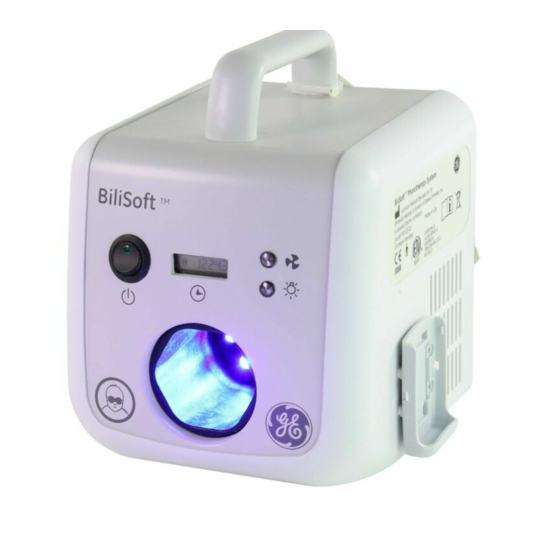
Chapter 3: Components and User Controls BiliSoft Light Box The light box contains the LED module, a power supply, a cooling system, and an overheating protection. The universal power supply allows the unit to be supplied via any standard AC main power source at either 50 or 60 Hertz that has voltages in the range of 90 to 264 V~. -
Page 20: Bilisoft Fiberoptic Light Pad Assembly
BiliSoft Fiberoptic Light Pad Assembly The fiberoptic light pad comes in two sizes – large and small. The LED light source in the BiliSoft light box is focused on the fiberoptic lenses at the end of the fiberoptic cable connector. The fiberoptic cable contains plastic fibers that transmit light from the light box to the light pad. -
Page 21: Soft Cover Options (Disposables)
BiliSoft Pad Cover or BiliSoft Nest when used with the patient. Soft Cover Options (Disposables) The BiliSoft Pad Cover and BiliSoft Nest are designed for use with both premature and full-term infants. The BiliSoft Pad Cover and BiliSoft Nest are available in small and large sizes to accommodate whichever fiberoptic light pad is used. - Page 22 Chapter 3: Components and User Controls © 2007 by General Electric Company. All rights reserved. M1110150 006...
-
Page 23: Chapter 4: Troubleshooting
Chapter 4: Troubleshooting CAUTION Insulation on electrical wiring can deteriorate with age. Check for brittle or deteriorated insulation on the power cord before each use and all other electrical wiring while performing troubleshooting or replacement of internal components. WARNING: Whenever the unit is plugged in, AC power is present. Use caution when cover is removed. NOTE: Potentiometers on the boards are set at the factory and are not to be adjusted in the field. - Page 24 Chapter 4: Troubleshooting Symptom Troubleshooting Steps 1. Check power connections and that the standby switch is on. B No light output. Check that the fiberoptic pad connector is fully inserted. 2. Check that the green power indicator on the standby switch is lit.
- Page 25 Chapter 4: Troubleshooting Symptom Troubleshooting Steps E Indicator lights not working. 1. Confirm failure condition. 2. Remove cover and check all connections. 3. Check voltage across affected indicator LED pins on Display PCB. If voltage is present, replace the Display PCB. If no voltage is present, replace the Control PCB.
- Page 26 Chapter 4: Troubleshooting Symptom Troubleshooting Steps 1. Replace the fiberoptic light pad. H Fiberoptic light pad, cable or connector is damaged. NOTE: See Operation and Maintenance Manual for approved cleaning procedure. J Fiberoptic pad connector switch not 1. Check that the fiberoptic pad connector is fully inserted, working and the standby switch is in the on position and the green indicator light is on.
-
Page 27: Chapter 5: Replacement/Checkout Procedures
Chapter 5: Replacement/Checkout Procedures WARNING: Whenever the unit is plugged in, AC power is present. Use caution when cover is removed. CAUTION Anytime the unit is disassembled (back cover is removed) the electrical safety tests and light intensity measurement procedure must be performed to assure that the unit is functioning properly. -
Page 28: Led Module Replacement
Chapter 5: Replacement/Checkout Procedures LED Module Replacement Figure Procedure 1. Use a Phillips screwdriver to remove the four screws and lockwashers that secure the rear LED module access cover. Rear cover 2. Remove the four LED module mounting screws. 3. Disconnect the ribbon cable J2. 4. -
Page 29: Air Filter Cleaning/Replacement
Chapter 5: Replacement/Checkout Procedures Air Filter Cleaning/Replacement Figure Procedure 1. The air filter can be vacuumed without removing it. 2. To remove the air filter, use a Phillips screwdriver to remove the four screws and lockwashers that secure the rear access cover. 3. -
Page 30: Accessing/Replacing Other Internal Components
Chapter 5: Replacement/Checkout Procedures Accessing/Replacing Other Internal Components Figure Procedure 1. Use a Phillips screwdriver to remove the four screws and lockwashers that secure the rear access cover. 2. Use a Phillips screwdriver to remove the five foot pads on the bottom of the unit. Remove the optional mounting bracket if installed. -
Page 31: Electrical Safety Checkout Procedure
3. Turn the BiliSoft LED Phototherapy System on using the standby switch on the front of the unit and allow it to run for five (5) minutes. 4. Place the fiberoptic light pad on a flat surface. Do not place the fiberoptic light pad inside of the BiliSoft Pad Cover or BiliSoft Nest at this time. - Page 32 (A + B + C + D + E + F) /6 = 70 * Using an Ohmeda Medical BiliBlanket Meter II NOTE: When the BiliSoft fiberoptic light pad is inserted into a BiliSoft Pad Cover or BiliSoft Nest, the nominal spectral irradiance is: •...
-
Page 33: Chapter 6: Spare Parts
Chapter 6: Spare Parts Part Numbers Figure 6-1 1. Foot Pad Kit M1098508 includes 5 foot pads D, L 2. Back Cover Kit M1110057 includes back plate and label. NOTE: When replacing the back plate, the old SN insert must C (4) be retained and C, M (4) - Page 34 Chapter 6: Spare Parts Part Numbers Figure 6-2 4. Handle M1098507 5. Enclosure Kit M1098512 includes enclosure, side label set. A, B (2) NOTE: Proper language label must be selected from the label set and applied to the product 6. Standby Switch M1110058 7.
- Page 35 Chapter 6: Spare Parts Part Numbers Figure 6-3 9. LED Module Kit P (4) K, O (4) M1098188 includes item #10, heatsink, and LED board 10. Fan Kit M1098497 includes mounting screws (4)) I, J 11. Fuse Kit 6600-0730- 214 includes 2 fuses (T3.15A @ 250V~, slo-blo type) 12.
- Page 36 Chapter 6: Spare Parts Part Numbers Figure 6-4 15. Top Plate Kit M1110054 includes ground label E (4) 16. LED Shutoff Switch Kit M1185735 * D, M * Refer to Note 1 after this table. H** (4), O** (4) ** For the old style (note proper G (4) pad connector,...
-
Page 37: Note 1: Service Kit Package For Control Pca
Standby Switch Harness M1185737 Bilisoft units manufactured with the new connector design can be distinguished from the old-design units based on their serial number. That is, units with serial number equal or greater than HFAN50501 are new- design units. Old-design units have serial numbers less than HFAN50501. If any of the four parts (M1185734, M1185735, M1185736, M1185737) need to be replaced for any reason, replace as follows: •... -
Page 38: Hardware Kits (Sold In Packs Of 10)
Chapter 6: Spare Parts Hardware Kits (sold in packs of 10) M1098517 M6 10mm, Phillips Machine screw M1120985 M6, External Tooth Lock Washer M1098616 M4 12mm, Phillips Machine Screw M1120986 M4 Nut M1098520 M4 10mm, Phillips Machine Screw, Flat Head M1120992 M3 8mm Thread-Forming Screws, Phillips M1098519... -
Page 39: Chapter 7: Accessories
Bracket, Dovetail Rail, female (for mounting to an Ohmeda dovetail rail or Giraffe Spot PT Lite roll 6600-0031-900 stand – order male bracket separately) BiliSoft Mounting Bracket, male (mounts the BiliSoft to Ohmeda mobile stand, Giraffe Spot PT Lite M1097110 roll stand, or Ohmeda dovetail rail – order the appropriate female bracket separately) - Page 40 Chapter 7: Accessories Accessories Stock Number Operation and Maintenance Manual, German M1110625 Operation and Maintenance Manual, Swedish M1110628 Operation and Maintenance Manual, Portuguese M1110632 Operation and Maintenance Manual, Polish M1110645 Operation and Maintenance Manual, Russian M1110986 Operation and Maintenance Manual, Finnish M1110988 Operation and Maintenance Manual, Greek M1110990...
- Page 41 Chapter 7: Accessories Accessories Stock Number User Reference Card, Czech M1128871 User Reference Card, Estonian M1128873 User Reference Card, Lithuanian M1128888 Power Cord, North America 6600-0730-207 Power Cord, Australian 6600-0574-614 Power Cord, United Kingdom 6600-0744-200 Power Cord, CE 6600-0745-200 Power Cord, Danish M1093124 Power Cord Indian M1153026...
- Page 42 Chapter 7: Accessories © 2007 by General Electric Company. All rights reserved. M1110150 006...
-
Page 43: Chapter 8: Specifications
Chapter 8: Specifications NOTE: All specifications are nominal and are subject to change without notice. Electrical Specifications Input 1.5A @ 100 – 240 V~, 50/60 Hz Fuses T3.15A @ 250V~, slo-blo type (qty. 2) Leakage Current < 300 μA @ 264 V~ Ground impedance <... -
Page 44: Performance Specifications
**The LED module life may vary when used in the actual clinical environment. Factors such as duty cycle and ambient temperature may impact the life of the LED module. Measure the irradiance and replace the LED module when the BiliSoft system is below specifications. -
Page 45: Regulatory Standards
FDA Class II 1632.6 (for BiliSoft Pad Covers and BiliSoft Nests) GE Healthcare has declared that this product conforms with the European Council Directive 93/42/EEC Medical Device Directive when it is used in accordance with the instructions provided in the Operation and Maintenance Manual. - Page 46 Chapter 8: Specifications © 2007 by General Electric Company. All rights reserved. M1110150 006...
-
Page 47: Chapter 9: Technical Reference
Chapter 9: Technical Reference The following information is provided for compliance to IEC 60601-2-50. 100% BiliSoft Output Ohmeda Medical BiliBlanket Light Meter Sensitivity Wavelength (nm) Average Total Irradiance for Bilirubin (measured with a spectroradiometer between 400-550 nm) = 10.5 mW•cm (bare fiberoptic pad, small) = 7.9 mW•cm... -
Page 48: Emc Guidance
Guidance and manufacturer’s declaration - electromagnetic immunity The BiliSoft Phototherapy System is intended for use in the electromagnetic environment specified below. The customer or the user of the BiliSoft Phototherapy System should assure that it is used in such an environment. - Page 49 IEC domestic environment. for 5 cycles 70 % Ut(30 5 cycles 61000-4-11 If the user of the BiliSoft % dip in Ut) for 25 cycles Phototherapy System 70 % Ut (30 % dip in Ut) <5% Ut(>95% dip in Ut)
- Page 50 Guidance and manufacturer’s declaration - electromagnetic immunity The BiliSoft Phototherapy System is intended for use in the electromagnetic environment specified below. The customer or the user of the BiliSoft Phototherapy System should assure that it is used in such an environment.
- Page 51 The BiliSoft Phototherapy System is intended for use in an electromagnetic environment in which radiated RF disturbances are controlled. The customer or the user of the BiliSoft Phototherapy System can help prevent electromagnetic interference by maintaining a minimum distance between portable and mobile RF communica¬tions equipment (transmitters) and the BiliSoft Phototherapy System as recommended below,...
- Page 52 Guidance and manufacturer’s declaration – electromagnetic emissions The BiliSoft Phototherapy System is intended for use in the electromagnetic environment specified below. The customer or the user of the BiliSoft Phototherapy System should assure that it is used in such an environment.
-
Page 53: Appendix Additional Safety Information
Appendix Additional Safety Information Statements This device should only be operated by personnel trained in its operation and familiar with the risks and benefits of this type of device. WARNING: To avoid the risk of electrical shock, this equipment must only be connected to a supply mains with protective earth. -
Page 54: Symbols
Appendix D: Additional Safety Information Symbols The following symbol appears on the unit: Symbol Description Consult accompanying documents. Do not place items in radiant heat path. Cover the patient’s eyes during phototherapy. Checkout Procedures Examine the unit for any missing or damaged labels. Specifications The product is designed to meet a life span of 7 years. - Page 55 This same warranty is made for a period of thirty (30) days with respect to expendable parts. The foregoing warranties shall not apply if the Product has been repaired other than by GE Healthcare or in accordance with written instructions provided by GE Healthcare, or altered by anyone other than GE Healthcare, or if the Product has been subject to abuse, misuse, negligence, or accident.
- Page 56 上海GE中国科技园 Tel + 1 954 744 5600 地址:中国上海市浦东张江高科技园华佗路1号, 201203 Tel + (8621) 38777888 Fax + (8621) 38777402 Brazil Only GE Healthcare Clinical Sytems Equipamentos Médicos Ltda Australia 1300 722 229 Av. Paulista, 37 - 13º andar China 800 810 8188 CEP: 01311-902 - Cerqueira César...
Need help?
Do you have a question about the BiliSoft and is the answer not in the manual?
Questions and answers