
Related Manuals for GIGAIPC iTXL-H610A


Summary of Contents for GIGAIPC iTXL-H610A
-
Page 1: Thin Mini-Itx Motherboard
(MH610AT-SI) Thin Mini-ITX Motherboard User’s Manual 1st Ed www.gigaipc.com... -
Page 2: Copyright Notice
While reasonable efforts have been made in the preparation of this document to assure its accuracy, GIGAIPC assumes no liabilities resulting from errors or omissions in this document, or from the use of the information contained herein. -
Page 3: Acknowledgement
Core, Atom are trademarks of Intel Corporation • • ITE is a trademark of Integrated Technology Express, Inc. IBM, PC/AT, PS/2, and VGA are trademarks of International Business • Machines Corporation. All other product names or trademarks are properties of their respective owners. www.gigaipc.com... -
Page 4: Packing List
Before setting up your product, please make sure the following items have been shipped: Item Quantity iTXL-H610A MB SATA power cable I/O Bracket If any of these items are missing or damaged, please contact your distributor or sales representative immediately. -
Page 5: About This Document
(if any), its specifications, dimensions, jumper/ connector settings/definitions, and driver installation instructions (if any), to facilitate users in setting up their product. Users may refer to the GIGAIPC.com for the latest version of this document. www.gigaipc.com... -
Page 6: Safety Precautions
Make sure the device is installed near a power outlet and is easily accessible. 10. Keep this device away from humidity. 11. Place the device on a solid surface during installation to prevent falls 12. Do not cover the openings on the device to ensure optimal heat dissipation. www.gigaipc.com... - Page 7 18. D O N O T L E AV E T H I S D E V I C E I N A N U N C O N T R O L L E D ENVIRONMENT WITH TEMPERATURES BEYOND THE DEVICE’S PERMITTED STORAGE TEMPERATURES (SEE CHAPTER 1) TO PREVENT DAMAGE. www.gigaipc.com...
-
Page 8: Fcc Statement
Il y a un risque d’explosion si la batterie est remplacée de façon incorrecte. Ne la remplacer qu’avec le même modèle ou équivalent recommandé par le constructeur. Recycler les batteries usées en accord avec les instructions du fabricant et les directives gouvernementales de recyclage. www.gigaipc.com... -
Page 9: China Rohs Requirements (Cn)
China RoHS Requirements (CN) 产品中有毒有害物质或元素名称及含量 GIGAIPC Main Board/ Daughter Board/ Backplane 有毒有害物质或元素 部件名称 铅 汞 镉 六价铬 多溴联苯 多溴二苯醚 (Pb) (Hg) (Cd) (Cr(VI)) (PBB) (PBDE) 印刷电路板 及其电 ○ ○ ○ ○ ○ ○ 子组件 外部信号 连接器 ○ ○ ○ ○... -
Page 10: China Rohs Requirement (En)
China RoHS Requirement (EN) Poisonous or Hazardous Substances or Elements in Products GIGAIPC Main Board/ Daughter Board/ Backplane Poisonous or Hazardous Substances or Elements Component Hexavalent Polybrominated Polybrominated Lead Mercury Cadmium Chromium Biphenyls Diphenyl Ethers (Pb) (Hg) (Cd) (Cr(VI)) (PBB) (PBDE) PCB &... -
Page 11: Table Of Contents
2.2.5 USB32_1 (USB 3.2 Gen 2x1 connector x 2) ....26 2.2.6 LAN1, LAN2 (GbE LAN connector x 2)......27 2.2.7 HDMI_DP (Display port (Top) & HDMI connector (bottom)) ............... 28 2.2.8 SATA4, SATA5 (SATA 6Gb/s connector) ......29 www.gigaipc.com... - Page 12 2.2.25 TPM (Trusted platform module connector) ....46 2.2.26 Battery (Battery connector) ......... 47 2.2.27 CLR_CMOS (Clear CMOS jumper) ......... 48 2.2.28 AT_CN (AT/ATX mode select jumper) ......49 Chapter 3 – BIOS Introduction ..............51 The Main Menu............. 52 Advanced ..............53 www.gigaipc.com...
- Page 13 3.3.9 NVMe Configuration ............. 63 3.3.10 Offboard SATA Controller Configuration ...... 64 3.3.11 Digital IO Port Configuration ........65 3.3.12 Tls Auth Configuration ..........66 Chipset ................67 Security ................. 69 Boot ................72 Save & Exit ..............73 www.gigaipc.com...
-
Page 14: Chapter 1 - Product Specifications
Chapter 1 Chapter 1 - Product Specifications www.gigaipc.com... - Page 15 179.7 154.9 132.1 11.8 www.gigaipc.com...
-
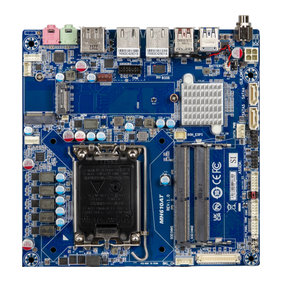
Page 16: Specifications
Specifications Motherboard iTXL-H610A (MH610AT-SI) Thin Mini-ITX form factor Form Factor 170W x 170D (mm) Support for 13th/12th Generation Intel® Core™ i9/i7/i5/i3 processors, Pentium® & Celeron® processors in the LGA1700 package TDP under 65W L3 cache varies with CPU Socket LGA 1700 Chipset Intel®... - Page 17 Motherboard iTXL-H610A (MH610AT-SI) 2 x Audio jacks (Line out, Mic in) 1 x HDMI 1 x Display Port Rear I/O 2 x RJ45 LAN Ports 2 x USB 3.2 Gen 2x1 2 x USB 3.2 Gen 1 1 x DC Jack (+12V/+19~24VDC)
-
Page 18: Chapter 2 - Hardware Information
Chapter 2 Chapter 2 – Hardware Information www.gigaipc.com... -
Page 19: Jumpers And Connectors
Jumpers and Connectors www.gigaipc.com... - Page 20 RI# pin RI#/5V/12V Select jumper for COM1 JCOM1 Port COM header COM1, COM2 COM1 : RS-232/422/485 & RI/5V/12V COM2 : RS-232 SYS_PANEL System Panel header SODIMM1, 2 x DDR4 SO-DIMM Sockets SODIMM2 LVDS LVDS connector Backlight Control header BKL_CN CPU_FAN CPU FAN connector www.gigaipc.com...
- Page 21 M.2 Slot, E-Key, Supports NGFF-2230 M.2 Slot, M-Key, Supports NGFF-2280 BUZZER Buzzer header SPKR Speaker out connector FP_Audio Front panel audio header SYS_FAN System Fan connector Trusted platform module connector Battery Battery connector CLR_CMOS Clear CMOS jumper AT/ATX mode select jumper AT_CN www.gigaipc.com...
-
Page 22: Io Connector Information
USB32_2 USB 3.2 Gen 1 connector x 2 USB32_1 USB 3.2 Gen 2x1 connector x 2 LAN1, LAN2 GbE LAN connector x 2 Display Port connector HDMI_DP HDMI connector LINE_OUT Line Out port (Green) MIC_IN Mic In port (Pink) www.gigaipc.com... -
Page 23: Dc_In1 (Dc In Jack)
2.2.2 DC_IN1 (DC In Jack) DC In Jack Connector PN Vendor 655-360-000 SHEN-MING www.gigaipc.com... -
Page 24: Dc_In2 (Atx 2X2 Pin Power Connector)
2.2.3 DC_IN2 (ATX 2x2 Pin Power connector) Pin 1 Power Connector Connector PN Vendor 740-81-04TW56 PINREX Pin No. Definition DC IN DC IN www.gigaipc.com... -
Page 25: Usb32_2 (Usb 3.2 Gen 1 Connector X 2)
2.2.4 USB32_2 (USB 3.2 Gen 1 connector x 2) USB Connector Connector PN Vendor UEA11121-8FS6-4F FOXCONN ABA-USB-079-K01 LOTES Definition Definition USB3_RX1n USB3_RX2n USB3_RX1p USB3_RX2p USB3_TX1n USB3_TX2n USB3_TX1p USB3_TX2p www.gigaipc.com... -
Page 26: Usb32_1 (Usb 3.2 Gen 2X1 Connector X 2)
2.2.5 USB32_1 (USB 3.2 Gen 2x1 connector x 2) USB Connector Connector PN Vendor 18-A5950-6A33-A TCONN Definition Definition USB3_RX1n USB3_RX2n USB3_RX1p USB3_RX2p USB3_TX1n USB3_TX2n USB3_TX1p USB3_TX2p www.gigaipc.com... -
Page 27: Lan1, Lan2 (Gbe Lan Connector X 2)
LAN1, LAN2 (GbE LAN connector x 2) LAN Connector State Description Orange On 1Gbps data rate Green On 100Mbps data rate 10Mbps data rate Connector PN Vendor Pin No. Definition Pin No. Definition RT7-GB-0003 TX1+ TX3+ TX1- TX3- TX2+ TX4+ TX2- TX4- www.gigaipc.com... -
Page 28: Hdmi_Dp (Display Port (Top) & Hdmi Connector (Bottom))
HDMI connector Pin No. Definition Pin No. Definition Pin No. Definition Pin No. Definition TX0p TX2p TX3n CLKn TX0n TX2n TX1p TX1p AUXp TX1n TX1n TX2p AUXn TX0p Hot Plug Detect Hot Plug TX0n TX2n 3.3V Detect TX3p 3.3V CLKp www.gigaipc.com... -
Page 29: Sata4, Sata5 (Sata 6Gb/S Connector)
2.2.8 SATA4, SATA5 (SATA 6Gb/s connector) SATA 4 SATA 5 SATA 6Gb/s Connector Connector PN Vendor WATM-07ABNB2BAUW3 WINWIN 770-83-07SW19 PINREX Pin No. Definition www.gigaipc.com... -
Page 30: Sata_Pwr (Sata Power Connector)
2.2.9 SATA_PWR (SATA Power connector) Pin 1 SATA Power Connector Connector PN Vendor 743-81-04TW00 PINREX Pin No. Definition www.gigaipc.com... -
Page 31: F_Usb2_1, F_Usb2_2 (Usb 2.0 Header)
2.2.10 F_USB2_1, F_USB2_2 (USB 2.0 header) Pin 1 USB 2.0 Header Connector PN Vendor 210-92-05GB04 PINREX PH10R53BAZ009 HORNGTONG Pin No. Definition No Pin www.gigaipc.com... - Page 32 2.2.11 GPIO_C NT (General purpose input/output Connector) Pin 1 GPIO Connector Pin No. Definition SMBus Clock SMBus DATA Pin No. Definition Connector PN Vendor GPIO-output_1 725-81-12TW00 PINREX GPIO-input_1 A2004WV-2X06P46 JOINT-TECH GPIO-output_2 GPIO-input_2 GPIO-output_3 GPIO-input_3 GPIO-output_4 GPIO-input_4 www.gigaipc.com...
-
Page 33: Jcom1 (Ri# Pin Ri#/5V/12V Select Jumper For Com1 Port)
2.2.12 JCOM1 (RI# pin RI#/5V/12V Select jumper for COM1 Port) Pin 1 JCOM1 Jumper Select Connector PN Vendor 210-92-03GB01 PINREX 1-2 Close: PH06R53BAZ000 HORNGTONG 5V (Power COM) 3-4 Close: RI (Stand COM) 5-6 Close: 12V (Power COM) www.gigaipc.com... -
Page 34: Com1, Com2 (Serial Port Header)
COM1 : Support RS-232/422/485 & RI/5V/12V Full Duplex Half Duplex COM2 : Support RS-232 For RI/5V/12V jumper setting, please see P. 32 TXD+ TXD- RXD- – RXD+ – – – – – – – – – No Connect – – RI/5V/12V – – www.gigaipc.com... -
Page 35: Sys_Panel (System Panel Header)
2.2.14 SYS_PANEL (System Panel header) Pin 1 System Panel Header Connector PN Vendor 210-92-05GW5W PINREX Pin No. Definition HD-P MPD-P HD-N MPD-N POWER-ON Reset Reserved www.gigaipc.com... -
Page 36: Sodimm1, Sodimm2 (2 X Ddr4 So-Dimm Sockets)
2.2.15 SODIMM1, SODIMM2 (2 x DDR4 SO-DIMM Sockets) www.gigaipc.com... -
Page 37: Lvds (Lvds Connector)
But below model no need to add. SPED0 A0~A3 is odd channel 0~3, A4~A7 is ev en channel. Note: *The LVDS output connector of the unit is only intended to be CLK2+ connected to an UL/IEC/EN approval CLK1+ equipment with fire enclosure. CLK2- CLK1- www.gigaipc.com... -
Page 38: Bkl_Cn (Backlight Control Header)
2.2.17 BKL_CN (Backlight Control header) Pin 1 Backlight Control header Connector PN Vendor 721-81-05TW00 PINREX A2001WV-05P146 JOINT-TECH Pin No. Definition 5V / 12V (Optional) Backlight enable www.gigaipc.com... -
Page 39: Cpu_Fan (Cpu Fan Connector)
2.2.18 CPU_FAN (CPU FAN connector) Pin 1 CPU Fan Connector Connector PN Vendor 744-81-045W11 PINREX Pin No. Definition Sense www.gigaipc.com... -
Page 40: M2E (M.2 Slot, E-Key, Supports Ngff-2230)
M.2 E Key Connector PCIe RXp PCIe RXn CLK_Dp Pin No. Definition Pin No. Definition CLK_Dn 3.3V SUSCLK 3.3V Clock request Reset Wakeup BT_Disable WLAN_Disable 3.3V 3.3V Pin No. Definition Pin No. Definition Connector PN Vendor PCIe TXp APCI0076-P002A LOTES PCIe TXn www.gigaipc.com... -
Page 41: M2M (M.2 Slot, M-Key, Supports Ngff-2280)
Clockn Wakeup PCIE3 TXn 3.3V Clockp PCIE3 TXp 3.3V 3.3V Pin No. Definition Pin No. Definition PCIE2 RXn 3.3V SUSClock PCIE2 RXp Detect 3.3V 3.3V PCIE2 TXn 3.3V PCIE2 TXp PCIe1 RXn Connector PN Vendor PCIe1 RXp 2E0BC41-F85CM-LH FOXCONN www.gigaipc.com... -
Page 42: Buzzer (Buzzer Header)
2.2.21 BUZZER (Buzzer header) Pin 1 Buzzer header Connector PN Vendor 712-71-02TW01 PINREX A1250WV-02P JOINT-TECH Pin No. Definition Buzzer www.gigaipc.com... -
Page 43: Spkr (Speaker Out Connector)
2.2.22 SPKR (Speaker out connector) Pin 1 Speaker Out Connector Connector PN Vendor 721-81-045W00 PINREX A2001WV-04P146 JOINT-TECH Pin No. Definition SPEAKER L+ SPEAKER L- SPEAKER R- SPEAKER R+ www.gigaipc.com... -
Page 44: Fp_Audio (Front Panel Audio Header)
2.2.23 FP_Audio (Front panel audio header) Pin 1 Front Audio Connector Connector PN Vendor 725-81-10TW00 PINREX A2004WV-2X05P46 JOINT-TECH Definition Definition MIC-LEFT JACKSENCE DETECT MIC-RIGHT DETECT LINE-LEFT LINE-RIGHT www.gigaipc.com... -
Page 45: Sys_Fan (System Fan Connector)
2.2.24 SYS_FAN (System Fan connector) Pin 1 System FAN Connector PN Vendor 744-81-045R11 PINREX Pin No. Definition www.gigaipc.com... -
Page 46: Tpm (Trusted Platform Module Connector)
2.2.25 TPM (Trusted platform module connector) Pin 1 TPM module connector Connector PN Vendor 52M-90-14GBE7 PINREX LCB25-I1424S01C-12 LIONCONN Definition Definition Clock 3.3V Reset No Pin 3.3V 3.3V SERIRQ TPM_CS www.gigaipc.com... -
Page 47: Battery (Battery Connector)
2.2.26 Battery (Battery connector) Pin 1 Battery Connector Connector PN Vendor 85205-0270L ACES A1250WV-S-02PC JOINT-TECH Pin No. Definition www.gigaipc.com... -
Page 48: Clr_Cmos (Clear Cmos Jumper)
2.2.27 CLR_CMOS (Clear CMOS jumper) Pin 1 Clear COMS jumper Pin No. Definition Clear CMOS 1-2 Close: Normal Operation (Default setting) 2-3 Close: Clear CMOS data. www.gigaipc.com... -
Page 49: At_Cn (At/Atx Mode Select Jumper)
2.2.28 AT_CN (AT/ATX mode select jumper) Pin 1 AT/ATX mode select jumper Connector PN Vendor 220-96-03GB01 PINREX PH03N2-7BAN000 HORNGTONG Pin No. Definition AT MODE Detect ATX MODE Jumper setting 1-2 Close : AT mode. 2-3 Close : ATX mode.(Default setting) www.gigaipc.com... -
Page 50: Chapter 3 - Bios
Chapter 3 Chapter 3 – BIOS www.gigaipc.com... -
Page 51: Introduction
Execute command or enter the submenu Increase the numeric value or make + changes Decrease the numeric value or make – changes General Help Previous Values Load Optimized Defaults Settings Save changes & Exit the BIOS Setup program Exit the BIOS Setup program www.gigaipc.com... -
Page 52: The Main Menu
ME FW version Shows ME firmware version Set the Date for the system System Date (Format : Week - Month - Day - Year) Set the time for the system System Time (Format : Hour - Minute - Second) www.gigaipc.com... -
Page 53: Advanced
Advanced The Advanced menu is to configure the functions of hardware settings through submenu. Use arrow keys to move among the items, and press <Enter> to access into the related submenu. www.gigaipc.com... -
Page 54: Tpm Configuration
3.3.1 TPM Configuration Use TPM Configuration submenu to choose TPM interface. Item Description PTT : Internal TPM (Default setting) TPM Device dTPM : External TPM (When using External TPM module or Selection having TPM chip on MB) www.gigaipc.com... - Page 55 Item Description Security Device Enabled : Enables TPM feature (Default setting) Support Disabled : Disables TPM feature None : No execution will be conducted (Default setting) Pending operation TPM clear : Set to clear data on TPM www.gigaipc.com...
-
Page 56: Cpu Configuration
Enabled : Enables CPU C states function (Default setting) Disabled : Disables CPU C states function To optimize CPU performance. Dual Tau Boost Enabled : Enables Dual Tau Boost function Disabled : Disables Dual Tau Boost function (Default setting) www.gigaipc.com... -
Page 57: Sata Configuration
3.3.3 SATA Configuration Item Description Serial ATA Port 1 shows 2.5" SATA HDD/SSD information Serial ATA Port 2 www.gigaipc.com... -
Page 58: It8786 Super Io Configuration
Serial Port 2 Enabled : Enables allows you to configure the serial port settings Configuration Disabled : if Disabled, displays no configuration for the serial port Device settings : Display the specified Serial Port base I/O address and IRQ www.gigaipc.com... -
Page 59: Hardware Monitor
Normal : Fan speed set by BIOS default (Default setting) Control Full Speed : Set Fan operates at full speed CPU Temperature Shows current CPU temperature System Shows current system temperature Temperature CPU Fan Speed Shows current CPU fan Speed SYS Fan Speed Shows current System fan Speed www.gigaipc.com... -
Page 60: S5 Rtc Wake Settings
Enable or Disable System to wake on a specific time. Wake system Disabled : Disables system to wake on a specific time (Default setting) from S5 Fixed Time : Enables system to wake on a specific time (Format : hr : min : sec) www.gigaipc.com... -
Page 61: Ami Graphic Output Protocol Policy
3.3.7 AMI Graphic Output Protocol Policy Item Description Choose default monitor output when there are more than one monitor plugged Output Select on the motherboard. www.gigaipc.com... -
Page 62: Network Stack Configuration
Disabled : Disables Ipv6 HTTP Support Enabled : Enables Ipv6 HTTP Support PXE boot wait time Wait time in seconds, or use ESC key to abort the PXE boot. Media detect count Number of times the presence of media will be checked. www.gigaipc.com... -
Page 63: Nvme Configuration
3.3.9 NVMe Configuration NVMe Configuration shows information when your M.2 NVMe PCIe SSD is installed. www.gigaipc.com... -
Page 64: Offboard Sata Controller Configuration
3.3.10 Offboard SATA Controller Configuration www.gigaipc.com... -
Page 65: Digital Io Port Configuration
Enabled : If Digital IO Output value/level is modified in OS, they will be memorized and kept. SOGPO_1 (Pin 1) SOGPI_1 (Pin 2) SOGPO_2 (Pin 3) SOGPI_2 (Pin 4) Configure Digital IO Input or Output values for each pin. SOGPO_3 (Pin 5) SOGPI_3 (Pin 6) SOGPO_4 (Pin 7) SOGPI_4 (Pin 8) www.gigaipc.com... -
Page 66: Tls Auth Configuration
Press [Enter] to configure advanced items : Server CA Configuration : Enroll Cert : Enroll Cert 1. Enroll Cert Using File 2. Cert GUID : Input digit character in 11111111-2222-3333-4444-1234567 890ab format. 3. Commit Changes and Exit 4. Discard Changes and Exit www.gigaipc.com... -
Page 67: Chipset
Power off : Do not power on when the power is back (Default setting) Loss Power on : System power on when the power is back Last state : Restore the system to the state before power loss occures www.gigaipc.com... - Page 68 Enable/Disable Watchdog Timer function Watchdog Timer Disabled : Disables Watchdog Timer function (Default setting) Enabled : Enables Watchdog Timer function Enable/Disable BIOS Lock function BIOS Lock Enabled : Enables BIOS Lock function (Default setting) Disabled : Disabled BIOS Lock funtion www.gigaipc.com...
-
Page 69: Security
To set up Administrator's password Administrator Minimum length : 3 Password Maximum length : 20 To set up User's password User Password Minimum length : 3 Maximum length : 20 Secure Boot Press <Enter> to configure the advanced items www.gigaipc.com... - Page 70 No : Cancel to restore factory settings Reset To Setup Yes : Agree to setup mode Mode No : Cancel to setup mode Enables expert users to modify Secure boot policy variables without full Key Management authentication Press <Enter> to configure the advanced items www.gigaipc.com...
- Page 71 These items allows you to enroll factory defaults or load Certificates from a Forbidden Signatures file. Authorized TimeStamps OsRecovery Signatures Device Guard ready system must not list ’Microsoft UEFI CA’ Certificate in MS UEFI CA Key Authorized Signature database(db) www.gigaipc.com...
-
Page 72: Boot
Enable/Disable Built-in EFI Shell Built-in EFI Shell Enabled : Enables Built-in EFI Shell Disabled : Disables Built-in EFI Shell (Default setting) Shows the information of the storage that be installed in the system Boot Option #1 Choose/set the boot priority www.gigaipc.com... -
Page 73: Save & Exit
Yes : Agree to load optimized defaults No : Cancel to load optimized defaults Enable/Disable Me FW image re-flash function Me FW Image Enabled : Enables Me FW image re-flash function Re-Flash Disabled : Disables Me FW image re-flash function (Default setting) www.gigaipc.com...
Need help?
Do you have a question about the iTXL-H610A and is the answer not in the manual?
Questions and answers