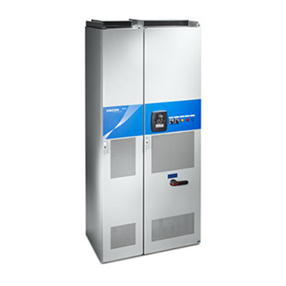
Vacon NXP Series User Manual
Frequency converters
Hide thumbs
Also See for NXP Series:
- User manual (86 pages) ,
- System hardware manual (83 pages) ,
- Installation quick manual (10 pages)


Need help?
Do you have a question about the NXP Series and is the answer not in the manual?
Questions and answers