Sign In
Upload
Manuals
Brands
Vacon Manuals
Controller
NXP series
Vacon NXP series Manuals
Manuals and User Guides for Vacon NXP series. We have
6
Vacon NXP series manuals available for free PDF download: Applications Manual, User Manual, System Hardware Manual, Quick Manual, Installation Quick Manual
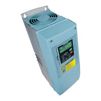
Vacon NXP series Applications Manual (392 pages)
all in one
Brand:
Vacon
| Category:
Controller
| Size: 2.5 MB
Table of Contents
About this Manual
3
Vacon
3
Table of Contents
7
1 Basic Application
11
Introduction
11
Motor Protection Functions in the Basic Application
11
Control I/O
12
Control Signal Logic in Basic Application
13
Basic Application - Parameter Lists
14
Monitoring Values (Control Keypad: Menu M1)
14
Basic Parameters (Control Keypad: Menu M2 -> G2.1)
15
Keypad Control (Control Keypad: Menu M3)
17
System Menu (Control Keypad: Menu M6)
18
Expander Boards
18
2 Standard Application
19
Introduction
19
Control I/O
20
Control Signal Logic in Standard Application
22
Standard Application - Parameter Lists
22
Monitoring Values (Control Keypad: Menu M1)
22
Basic Parameters (Control Keypad: Menu M2 -> G2.1)
24
Input Signals (Control Keypad: Menu M2 -> G2.2)
26
Output Signals
29
Drive Control Parameters
32
Prohibit Frequency Parameters (Control Keypad: Menu M2 -> G2.5)
33
Motor Control Parameters (Control Keypad: Menu M2 -> G2.6)
34
Protections
38
Autorestart Parameters (Control Keypad: Menu M2 -> G2.8)
40
Keypad Control (Control Keypad: Menu M3)
40
System Menu (Control Keypad: Menu M6)
41
Expander Boards
41
3 Local/Remote Control Application
42
Introduction
42
Control I/O
43
Control Signal Logic in Local/Remote Application
45
Local/Remote Control Application - Parameter Lists
45
Monitoring Values (Control Keypad: Menu M1)
45
Basic Parameters (Control Keypad: Menu M2 -> G2.1)
47
Input Signals (Control Keypad: Menu M2 -> G2.2)
49
Output Signals
55
Drive Control Parameters
59
Prohibit Frequency Parameters (Control Keypad: Menu M2 -> G2.5)
60
Motor Control Parameters (Control Keypad: Menu M2 -> G2.6)
61
Protections
65
Autorestart Parameters (Control Keypad: Menu M2 -> G2.8)
67
Keypad Control (Control Keypad: Menu M3)
67
System Menu (Control Keypad: Menu M6)
68
Expander Boards
68
4 Multi-Step Speed Control Application
69
Introduction
69
Control I/O
70
Control Signal Logic in Multi-Step Speed Control Application
72
Multi-Step Speed Control Application - Parameter Lists
72
Monitoring Values (Control Keypad: Menu M1)
72
Basic Parameters (Control Keypad: Menu M2 -> G2.1)
74
Input Signals (Control Keypad: Menu M2 -> G2.2)
77
Output Signals
81
Drive Control Parameters
85
Prohibit Frequency Parameters (Control Keypad: Menu M2 -> G2.5)
86
Motor Control Parameters (Control Keypad: Menu M2 -> G2.6)
87
Protections (Control Keypad: Menu M2 -> G2.7)
91
Autorestart Parameters (Control Keypad: Menu M2 -> G2.8)
93
Keypad Control (Control Keypad: Menu M3)
93
System Menu (Control Keypad: Menu M6)
94
Expander Boards
94
5 PID Control Application
95
Introduction
95
Control I/O
96
Control Signal Logic in PID Control Application
98
PID Control Application - Parameter Lists
98
Monitoring Values (Control Keypad: Menu M1)
98
Basic Parameters (Control Keypad: Menu M2 -> G2.1)
101
Input Signals
104
Output Signals
111
Drive Control Parameters
115
Prohibit Frequency Parameters (Control Keypad: Menu M2 -> G2.5)
116
Motor Control Parameters (Control Keypad: Menu M2 -> G2.6)
117
Protections
121
Autorestart Parameters (Control Keypad: Menu M2 -> G2.8)
124
Keypad Control (Control Keypad: Menu M3)
124
System Menu (Control Keypad: Menu M6)
125
Expander Boards
125
6 Multi-Purpose Control Application
126
Introduction
126
Control I/O
128
Control Signal Logic in Multi-Purpose Control Application
129
Multi-Purpose Control Application - Parameter Lists
130
Monitoring Values (Control Keypad: Menu M1)
130
Basic Parameters (Control Keypad: Menu M2 -> G2.1)
142
Input Signals
145
Output Signals
155
Drive Control Parameters
165
Prohibit Frequency Parameters (Control Keypad: Menu M2 -> G2.5)
167
Motor Control Parameters (Control Keypad: Menu M2 -> G2.6)
168
Protections
181
Autorestart Parameters (Control Keypad: Menu M2 -> G2.8)
186
Fieldbus Parameters (Control Keypad: Menu M2 ->G2.9)
187
Torque Control Parameters (Control Keypad: Menu M2 -> G2.10)
190
NXP Drives: Master Follower Parameters (Control Keypad: Menu M2 -> G2.11)
193
Keypad Control (Control Keypad: Menu M3)
194
System Menu (Control Keypad: Menu M6)
195
Expander Boards
195
7 Pump and Fan Control Application
196
Introduction
196
Control I/O
197
Control Signal Logic in Pump and Fan Control Application
200
Pump and Fan Control Application - Parameter Lists
200
Monitoring Values (Control Keypad: Menu M1)
200
Basic Parameters (Control Keypad: Menu M2 -> G2.1)
203
Input Signals
206
Output Signals
214
Drive Control Parameters
222
Prohibit Frequency Parameters (Control Keypad: Menu M2 -> G2.5)
223
Motor Control Parameters (Control Keypad: Menu M2 -> G2.6)
224
Protections
226
Autorestart Parameters (Control Keypad: Menu M2 -> G2.8)
229
System Menu (Control Keypad: Menu M6)
233
8 Parameter Descriptions
234
Keypad Control Parameters
365
Master/Follower Function (NXP Only)
367
Master/Follower Link Physical Connections
367
Optical Fibre Connection between AC Drives with OPTD2
367
Parameters of Stall Protection (Ids 709 to 712)
370
Parameters of Underload Protection (Ids 713 to 716)
370
Fieldbus Control Parameters (Ids 850 to 859)
371
Process Data out (Slave -> Master)
371
Current Scaling in Different Size of Units
371
Process Data in (Master -> Slave)
372
Closed Loop Parameters (Ids 612 to 621)
373
Terminal to Function" (TTF) Programming Principle
374
Defining an Input/Output for a Certain Function on Keypad
374
Defining a Terminal for a Certain Function with Ncdrive Programming Tool
375
Defining Unused Inputs/Outputs
376
Speed Control Parameters (Application 6 Only)
377
Automatic Changing between Drives (Application 7 Only)
378
Interlock Selection (P2.9.23)
380
Examples of Autochange and Interlock Selection
381
Pump and Fan Automatics with Interlocks and no Autochange
381
Pump and Fan Automatics with Interlocks and Autochange
381
9 Fault Tracing
384
Fault Codes
384
Advertisement
Vacon NXP series User Manual (102 pages)
Frequency converters
Brand:
Vacon
| Category:
Industrial Equipment
| Size: 2.66 MB
Table of Contents
Table of Contents
4
Safety
6
Warnings
6
Safety Instructions
6
Vacon • 5
6
Earthing and Earth Fault Protection
7
Running the Motor
7
Introduction
8
Manufacturer's Declaration of Conformity
9
Receipt of Delivery
10
Type Designation Code
10
NX Type Designation
10
NXC Additional Option Codes
11
Cabling (C-Group)
11
External Terminals (T-Group)
11
Input Device (I-Group)
11
Main Circuit (M-Group)
11
Output Filters (O-Group)
11
Protection Devices (P-Group)
11
General (G-Group)
11
Auxiliary Equipment (A-Group)
12
Door Mounted (D-Group)
12
Storage
13
Maintenance
13
Warranty
14
Technical Data
15
Power Ratings
15
Vacon NXP/C - Mains Voltage 380-500 V
15
Vacon NXC Regenerative Low Harmonic Drives - Mains Voltage 380-500 V
16
Vacon NXP/C 6 - Mains Voltage 500-690 V
17
Vacon NXC Regenerative Low Harmonic Drives - Mains Voltage 525-690 V
18
Technical Data
19
Mounting
21
Dimensions
21
Lifting the Unit out of the Transport Packaging
23
Fixing the Unit to the Floor or to the Wall
23
Fixing to the Floor and to the Wall
24
Fixing to the Floor Only
24
AC Choke Connections
25
Auxiliary Voltage Transformer Tappings
26
Cooling
27
Free Space Around the Cabinet
27
Power Losses
29
Cabling and Connections
30
Understanding the Power Unit Topology
30
Power Connections
32
LCL Filter Wiring Diagram of NXC Regenerative Low-Harmonic Drive
32
Mains and Motor Cables
34
Thermal Supervision of Option +ODU
43
DC Supply and Brake Resistor Cables
43
Control Cable
43
Cable and Fuse Sizes, 380-500V Units
44
Cable and Fuse Sizes, 500/525-690V Units
47
Low Harmonic Regenerative Cabinet Drive
50
NXC Low-Harmonic Regenerative Cabinet Pre-Charging and MCCB Operating Instructions
50
Manual Operation (MAN)
50
Remote Operation (REM)
51
Automatic Operation (AUTO)
52
Circuit-Breaker TRIP Due to Overload or Short-Circuit
52
Installation Instructions
54
Cable Installation and the UL Standards
55
Cable and Motor Insulation Checks
56
Control Unit
57
Control Connections
58
Control Terminal Signals
60
Connecting Power Supply and Internal Control Cables
64
Optic Fibre Cables, Signal Listing and Connections
65
Control Keypad
66
Indications on the Keypad Display
66
Drive Status Indications
66
Control Place Indications
67
Status Leds (Green - Green - Red)
67
Text Lines
67
Keypad Push-Buttons
68
Button Descriptions
68
Navigation on the Control Keypad
69
Monitoring Menu (M1)
71
Parameter Menu (M2)
72
Keypad Control Menu (M3)
74
Active Faults Menu (M4)
76
Fault History Menu (M5)
78
System Menu (M6)
79
Expander Board Menu (M7)
94
Further Keypad Functions
94
Commissioning
95
10.1 Safety
95
10.2 Commissioning of the Frequency Converter
95
Fault Tracing
98
11.1 Fault Time Data Record
98
11.2 Fault Codes
99
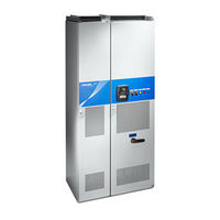
Vacon NXP series System Hardware Manual (83 pages)
AC drives system drive hardware manual
Brand:
Vacon
| Category:
DC Drives
| Size: 21.7 MB
Table of Contents
Table of Contents
3
1 Introduction
5
Revision History
5
Scope of Supply
5
Related Brochures and Manuals
5
Definitions and Abbreviations
6
Project Specifications
7
Parameters
7
Sections and Options
8
System Layout and Footprint Drawings
8
Supplied Documentation
8
Storage
9
Lifting and Moving the Cabinet Sections
10
2 Safety
11
Warnings
12
Cautions
13
Grounding and Ground Fault Protection
14
3 Available Sections
15
Auxiliary Device Section
15
Main Incoming Section
16
Non-Regenerative Front-End Section
18
Active Front-End Section
20
Inverter Unit Section
22
Drive Sizes FR4-FR8
22
Drive Sizes FI9-FI14
25
Dynamic Brake Section
28
Transport Split Unit
29
4 Installation
30
Installation Procedure
30
Preparing the Installation Site
31
Free Space Around the Cabinet
31
Mounting the Cabinets
32
Fixing the Cabinet to the Floor and Wall
32
Back-To-Back Installation
33
Connecting the Busbars
34
Side-By-Side Connection
34
Back-To-Back Connection
35
Fixing the Cabinet Frames to each Other
36
Cabling
37
Grounding
37
Mains and Motor Connection
37
EMC Grounding
42
Installation of Ferrite Rings (+OCM) on the Motor Cable
42
Control Connections
43
Auxiliary Low-Voltage Connections
44
Screw Tightening Torques
45
5 Service
55
Warranty
55
Maintenance
55
Removing the Drives from the Cabinet
56
Ius_4 / Ius_6
56
Ius_7 / Ius_8
57
Ius_9 / Ius_10
58
Ius_12
61
Ius_13 / Ius_14
64
6 Technical Information
67
Control and Interface
67
Control Without Speed Feedback (Open Loop)
67
Control with Speed Feedback (Closed Loop)
67
Load Definitions
67
Pump and Fan Load
68
OL( N Base ) > OL
69
N Max ) for Constant Torque Load
69
Starting Torque >> OL( N Max ) for Constant Torque Load
70
OL( N Base ) > OL( N Max ) for Constant Power Load
71
Max ) for Constant Power Load
72
Technical Specifications for VACON ® Drives
73
NXN - Non-Regenerative Front End Units
73
NXA - Active Front-End Units
75
NXI - Inverter Units
77
NXB - Brake Chopper Units
82
Advertisement
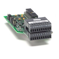
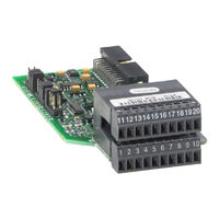
Vacon NXP series User Manual (86 pages)
basic i/o boards; expander i/o boards; adapter i/o boards
Brand:
Vacon
| Category:
Controller
| Size: 4.14 MB
Table of Contents
Table of Contents
3
1 General Information
4
Board Slots on the Control Board of VACON® NXS and NXP
4
Vacon
4
Board Slots on the Control Board of VACON® NXL
5
Option Board Types
6
Technical Data
7
Isolation
8
Analogue Inputs (Ma/V)
8
Analogue Outputs (Ma/V)
8
Control Voltage (+24V/EXT +24V)
8
Digital Input Signal Conversion
9
Hardware Protections
11
Terminal Block Coding
11
Board Slot Guides and Allowed Slots
11
Type Identification Number
12
Defining Functions to Inputs and Outputs
12
Defining a Terminal for a Certain Function with Ncdrive Programming Tool
13
Option Board Related Parameters
14
2 Installation of VACON® Option Boards
15
Control Cables
17
Cable Grounding
17
Board Information Sticker
18
3 Descriptions of VACON® Option Boards
19
Basic Boards OPTA
19
Opta1
20
Opta2
23
Opta3
24
Opta4
25
Opta5
31
Opta7
35
Opta8
41
Opta9
44
Optal
45
Optae
47
Optan
51
I/O Expander Boards OPTB
55
Optb1
56
Optb2
58
Optb4
59
Optb5
60
Optb8
62
Optb9
65
Optbb
66
Optbh
71
Adapter Boards OPTD
73
Optd1
73
Optd2
75
Optd3
79
Optd6
81
4 VACON® Option Boards - Operational Details
83
Vacon NXP series Quick Manual (20 pages)
Brand:
Vacon
| Category:
Controller
| Size: 4.92 MB
Table of Contents
Table of Contents
3
Cooling / Refroidissement / Kühlung / Raffreddamento / Refrigeración / Refrigeração / 冷却
4
Cable Installation / Installation des Câbles / Kabelinstallation / Installazione Dei Cavi / Instalación de Los Cables / Instalação Do Cabo / 电缆安装
5
En Control Panel and Keypad
6
Control Terminals
7
Fr Panneau Opérateur
8
Bornes de Commande
9
De Steuertafel und Tastenfeld
10
Steueranschlüsse
11
It Pannello DI Controllo E Pannello DI Comando
12
Morsetti DI Controllo
13
Es Cuadro de Control y Panel
14
Terminales de Control
15
Pt- Br
16
Painel de Controle E Teclado
16
Zh 控制面板和键盘
18
控制端子
19
Vacon NXP series Installation Quick Manual (10 pages)
ip00 modules frames fr9 to fr14
Brand:
Vacon
| Category:
Power Supply
| Size: 0.84 MB
Table of Contents
Table of Contents
3
1 Delivered Modules / Installing AC Chokes and Power Module
4
Products Included in the Delivery
4
Lifting the Power Module
4
Installing the Power Module
5
2 Ventilation
6
Steering the Internal Air Flow
6
Arranging Ventilation of the Enclosure
7
3 Grounding and Cabling the Unit
8
Connecting the Internal Power Cable
8
Installing the Optical Fibers
9
Installing the Motor Cable
9
Advertisement
Related Products
Vacon nxp/c
Vacon NXP 0820 5
Vacon NXP 0920 5
Vacon NXP 1030 5
Vacon NXP 0820 6
Vacon NXP 0650 6
Vacon NXP 0750 6
Vacon NX series
Vacon NX ACTIVE FRONT END II
Vacon NX_ 0205 2
Vacon Categories
Controller
Media Converter
DC Drives
Inverter
Power Supply
More Vacon Manuals
Login
Sign In
OR
Sign in with Facebook
Sign in with Google
Upload manual
Upload from disk
Upload from URL