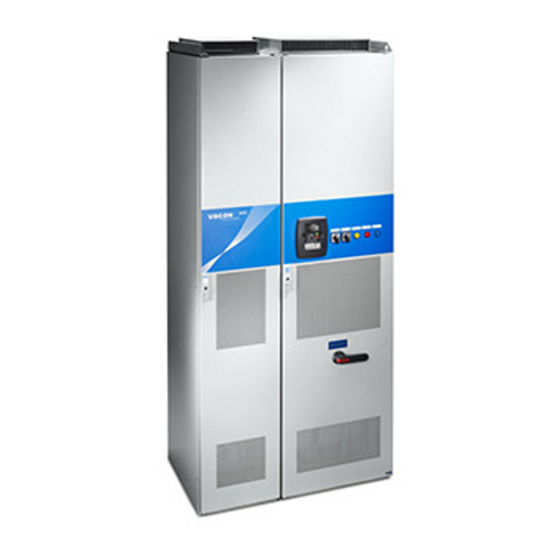
Summarization of Contents
Safety
Warnings
Important warnings for safe operation and handling of the frequency converter.
Safety instructions
Critical safety instructions for working with live electrical components.
Earthing and earth fault protection
Guidelines for proper earthing and earth fault protection measures.
Running the motor
Safety considerations and warnings related to motor operation.
Introduction
Manufacturer's declaration of conformity
Declaration of conformity to EMC and safety directives.
Receipt of Delivery
Type designation code
Explanation of the Vacon NXC type designation code for product identification.
NXC additional option codes
Listing and explanation of optional hardware features for NXC enclosures.
Storage
Recommendations for proper storage conditions and temperature limits.
Maintenance
Guidelines for proactive maintenance and cleaning procedures.
Warranty
Information regarding the manufacturer's warranty terms and conditions.
Technical Data
Power ratings
Table detailing power ratings, loadability, and dimensions for NXC drives.
Technical data
Comprehensive technical specifications including electrical, ambient, and enclosure data.
Mounting
Dimensions
Dimensional drawings and tables for Vacon NXC cabinet sizes.
Lifting the unit out of the transport packaging
Instructions and safety notes for lifting and handling the converter unit.
Fixing the unit to the floor or to the wall
Methods for securely mounting the cabinet to the floor or wall.
AC choke connections
Instructions for connecting AC chokes, including wiring diagrams and voltage settings.
Auxiliary voltage transformer tappings
Guidance on setting auxiliary voltage transformer tappings for mains voltage.
Cooling
Information on required free space and cooling air for proper operation.
Power losses
Formula for estimating heat losses at nominal conditions for ventilation planning.
Cabling and Connections
Understanding the power unit topology
Diagrams illustrating the topology of mains and motor connections for NXC drives.
Power connections
Detailed instructions and diagrams for making power connections, including LCL filters.
LCL filter wiring diagram of NXC regenerative low-harmonic drive
Detailed wiring diagram of the LCL filter for regenerative low-harmonic drives.
Mains and motor cables
Guidelines for connecting mains, motor, and control cables, including EMC grounding.
Cable and fuse sizes, 380-500V units
Tables specifying recommended cable types, sizes, and fuse ratings for 380-500V units.
Cable and fuse sizes, 500/525-690V units
Tables specifying recommended cable types, sizes, and fuse ratings for 500-690V units.
Low Harmonic Regenerative Cabinet Drive
NXC Low-Harmonic Regenerative Cabinet Pre-Charging and MCCB Operating Instructions
Operating instructions for pre-charging circuits and MCCB control in NXC drives.
Manual operation (MAN)
Procedures for manual control of the MCCB and charging circuit.
Remote operation (REM)
Instructions for controlling the MCCB and charging circuit from a remote system.
Automatic operation (AUTO)
Steps for automatic pre-charging and MCCB closing when supply is energized.
Circuit-Breaker TRIP due to overload or short-circuit
Information on how circuit breakers trip and the MCCB FAULT indicator.
Installation Instructions
Cable installation and the UL standards
UL regulations for cable selection and tightening torque specifications.
Cable and motor insulation checks
Procedures for verifying insulation resistance of motor, mains, and brake resistor cables.
Control unit
Overview of the control unit, its boards, and connections.
Control connections
Detailed control connections for basic I/O and relay boards.
Connecting power supply and internal control cables
Steps for connecting power supply and internal control/fiber optic cables.
Optic fibre cables, signal listing and connections
Information on optic fibre cables, their signal listings, and connection diagrams.
Control Keypad
Indications on the Keypad display
Explanation of status indicators, control place symbols, and text line information.
Drive status indications
Description of status indicators for RUN, STOP, READY, ALARM, and FAULT.
Keypad push-buttons
Identification and descriptions of the nine push-buttons on the control keypad.
Navigation on the control keypad
Guide to navigating menus and submenus using keypad buttons.
Monitoring menu (M1)
How to access and use the Monitoring menu (M1) for signal checking.
Parameter menu (M2)
Procedure for entering and editing parameter values via the Parameter menu (M2).
Keypad control menu (M3)
How to select control place, edit frequency reference, and change motor direction.
Active faults menu (M4)
Accessing and interpreting active faults and fault types.
Fault history menu (M5)
Navigating and managing the fault history memory.
System menu (M6)
Accessing system functions like language, application selection, and parameter management.
Expander board menu (M7)
Checking and editing parameters associated with expander boards.
Commissioning
Safety
Critical safety precautions to be observed before commissioning.
Commissioning of the frequency converter
Step-by-step guide for commissioning the frequency converter after installation.
Fault Tracing
Fault time data record
Accessing recorded data at the time of a fault for diagnosis.
Fault codes
A table listing fault codes, their possible causes, and correcting measures.


Need help?
Do you have a question about the NXC Series and is the answer not in the manual?
Questions and answers