Quantum DXi6900 Field Service Manual
With dxi 3.4.0 software
Hide thumbs
Also See for DXi6900:
- User manual (400 pages) ,
- Field service manual (274 pages) ,
- Installation manual (82 pages)
Table of Contents
Advertisement
Quick Links
Advertisement
Table of Contents

Related Manuals for Quantum DXi6900


Summary of Contents for Quantum DXi6900
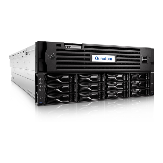
- Page 1 Field Service Manual Quantum DXi6900 G2 with DXi 3.4.0 Software 6-68448-05...
- Page 2 Artico, Be Certain (and the Q brackets design), DLT, DXi, DXi Accent, DXi V1000, DXi V2000, DXi V4000, FlexTier, GoVault, Lattus, NDX, the Q logo, the Q Quantum logo, Q-Cloud, Quantum (and the Q brackets design), the Quantum logo, Quantum Be Certain (and the Q brackets design), Quantum Vision, Scalar, StorageCare, StorNext, SuperLoader, Symform, the Symform logo (and design), vmPRO, and Xcellis are either registered trademarks or trademarks of Quantum Corporation and its affiliates in the United States and/or other countries.
-
Page 3: Table Of Contents
Node 10 GBaseT Ethernet Port Indicators Node Power Supply Indicators DXi6900 G2 Array and Expansion Modules DXi6900 G2 Array and Expansion Module Front Panel Features and Indicators Array and Expansion Module Hard Drive Carrier Indicators Array Module Rear Panel Indicators... - Page 4 Accessing Remote Management Locating DXi6900 G2 Serial Numbers Chapter 2: Service Menus Service Menus Overview Connecting to the DXi6900 G2 Node DXi6900 G2 Passwords Connecting to the System Node Using the Service Port Connecting to the System Node Using the iDRAC Port...
- Page 5 Replacing Node Hard Drives Obtaining a Replacement Node Hard Drive Replacing a Node Hard Drive Replacing Node Power Supplies Obtaining a Replacement Node Power Supply Replacing a Node Power Supply Replacing Node Cooling Fans Quantum DXi6900 G2 Field Service Manual...
- Page 6 Replacing the Processor and Heatsink Replacing the Node Hard Drive Backplane Obtaining a Replacement Hard Drive Backplane Replacing the Hard Drive Backplane Replacing the Node System Board Obtaining a Replacement System Board Replacing the System Board Quantum DXi6900 G2 Field Service Manual...
- Page 7 Obtaining a Replacement Expansion Module ESM Canister Replacing an Expansion Module ESM Canister Replacing an Array or Expansion Module Obtaining a Replacement Array or Expansion Module Chassis Replacing the Array or Expansion Module Chassis Additional Removal and Replacement Procedures Quantum DXi6900 G2 Field Service Manual...
- Page 8 Removing and Installing the Cable Retention Bracket Removing and Installing the Information Tag DXi6900 G2 Replacement Cables Chapter 4: BIOS Settings Updating the DXi6900 G2 BIOS Required DXi6900 G2 BIOS Settings Chapter 5: Cabling Diagrams DXi6900 G2 Cabling Diagrams Quantum DXi6900 G2 Field Service Manual viii...
-
Page 9: Preface
Preface This manual introduces the Quantum DXi6900 G2 disk backup solution and discusses: System operations Configuration Web interface Basic troubleshooting Service menus and FRU replacement Audience This manual is written for Quantum DXi6900 G2 field service engineers Note: It is useful for the audience to have a basic understanding of UNIX® and backup/recovery systems. - Page 10 (binary/1024). Product Safety Statements Quantum will not be held liable for damage arising from unauthorized use of the product. The user assumes all risk in this aspect. This unit is engineered and manufactured to meet all safety and regulatory requirements. Be aware that improper use may result in bodily injury, damage to the equipment, or interference with other equipment.
- Page 11 Preface Contacts For information about contacting Quantum, including Quantum office locations, go to: https://www.quantum.com/aboutus/contactus/index.aspx Quantum DXi6900 G2 Field Service Manual...
- Page 12 - Submit online service requests, update contact information, add attachments, and receive status updates via email. Online Service accounts are free from Quantum. That account can also be used to access Quantum’s Knowledge Base, a comprehensive repository of product support information. Get started at: https://www.quantum.com/customercenter/...
- Page 13 Preface Worldwide End-User Product Warranty For more information on the Quantum Worldwide End-User Standard Limited Product Warranty: https://www.quantum.com/serviceandsupport/warrantyinformation/index.aspx Quantum DXi6900 G2 Field Service Manual xiii...
-
Page 14: Chapter 1: Basic Operations
Turning On and Shutting Down the System Accessing Remote Management Locating DXi6900 G2 Serial Numbers Basic Operations Overview This chapter describes the hardware features and basic operation of DXi6900 G2 systems and includes the following sections: DXi6900 G2 Node on page 3 Array and Expansion Modules... -
Page 15: Determining The Dxi6900 Model
Locating DXi6900 Serial Numbers Determining the DXi6900 Model You will need to determine if the DXi system is a DXi6900 G1 or G2. Model information is located on the pull- out information tag on the front of the Node (see Figure 1 below). -
Page 16: Dxi6900 G2 Node
The Node contains 16 drive carriers. In addition, all network connections are made on the Node. All DXi6900 G2 systems include one Node. The DXi6900 G2 Node has a series of LED indicators and buttons located on the front and back of each component: Node Front Panel Features and Indicators below... - Page 17 Chapter 1: Basic Operations DXi6900 G2 Node New DXi Bezel A new DXi bezel is available. Please contact your account sales manager to purchase additional new bezels. Figure 4: DXi6900 Node Front View Quantum DXi6900 G2 Field Service Manual...
- Page 18 Chapter 1: Basic Operations DXi6900 G2 Node Table 1: DXi6900 Node - Front Panel LED Indicators, Buttons, and Connectors Item Indicator, Button, or Icon Description Connector Power-on indicator, power The power-on indicator lights when the system power is on. button.
-
Page 19: Node Rear Panel Connectors
Unplugging a SAS cable while the system is powered on may result in data loss. 10 GbE Cable Types Depending on the configuration, Quantum DXi6900 G2 systems support one of the following 10 GbE cable types: 10 GbE optical cable lengths of up to 300... - Page 20 DXi6900 G2 Node 10 GbE Twinax cable Quantum recommends using the approved 5 meter Twinax cable type that is shipped with the DXi6900 G2 system. This cable is compatible with Cisco 5000 Series Data Center Class switches. The 10 GbE Copper (Twinax) cable options that Quantum provides do not support all switches.
- Page 21 USB 2.0 connectors (2) Caution: Use of connected peripheral devices, such as a USB or PS/2 keyboard and mouse or a VGA display, is not supported and may cause incorrect system operation. Quantum DXi6900 G2 Field Service Manual...
-
Page 22: Node Hard Drive Carrier Indicators
* 2 x 10 Gb Ethernet = 2 x 10 GbE (SFP+) or 2 x 10 GBase-T Ethernet ports Node Hard Drive Carrier Indicators Each DXi6900 G2 hard drive carrier in the Node module has two LED indicators (see Figure 6 on the next... - Page 23 Caution: Do not remove a drive that has not failed. Instead, only remove a drive that has failed. If you accidentally remove a good drive, wait 30 seconds before reinserting the drive. Figure 6: DXi6900 G2 Hard Drive Carrier LEDs 1 - Drive activity indicator (green) 2 - Drive status indicator (green and amber)
-
Page 24: Node 1 Gbe Ethernet Port Indicators
Chapter 1: Basic Operations DXi6900 G2 Node Node 1 GbE Ethernet Port Indicators Each 1 GbE Ethernet port on the DXi6900 G2 Node rear panel has two LED indicators (see Figure 7 below): Link indicator Off - Indicates the port is not connected to the network. -
Page 25: Node 10 Gbaset Ethernet Port Indicators
Port 1 Port 2 Link indicators Activity Indicators Node 10 GBaseT Ethernet Port Indicators Each 10 GBase-T port on the DXi6900 G2 Node rear panel has two LED indicators (see Figure 9 on the next page): Link indicator Off - Indicates the port is not connected to the network. -
Page 26: Node Power Supply Indicators
1 - Activity Indicator 2 - Link Indicator Node Power Supply Indicators Each DXi6900 G2 Node power supply has an illuminated translucent handle that serves as an indicator to show whether power is present or whether a power fault has occurred (see... -
Page 27: Dxi6900 G2 Array And Expansion Modules
12 drive carriers and provides 34 TB of licensable storage. The DXi6900 G2 can include 1 or 2 Array modules (RBODs). Array modules connect to the Node and contain dual RAID controllers, which provide storage management logic. The DXi6900 G1/G2 includes 0 to 13 Expansion modules (EBODs), which connect in a chain to the Array modules, and which provide additional storage capacity only. -
Page 28: Dxi6900 G2 Array And Expansion Module Front Panel Features And Indicators
Keys). To purchase a storage capacity upgrade license, contact Quantum Customer Support. The DXi6900 Array and Expansion modules have a series of LED indicators and buttons located on the front and back of each component: Array and Expansion Module Front Panel Features and Indicators... - Page 29 Chapter 1: Basic Operations DXi6900 G2 Array and Expansion Modules Figure 11: DXi6900 G2 Array and Expansion Module LED Indicators – Front Panel Table 1: Array and Expansion Module LEDs and Buttons Item Button/LED Description Enclosure locate (white) Indicates the location of the enclosure within the system.
-
Page 30: Array And Expansion Module Hard Drive Carrier Indicators
Chapter 1: Basic Operations DXi6900 G2 Array and Expansion Modules Array and Expansion Module Hard Drive Carrier Indicators The individual hard drive sleds contain LEDs that indicate the health condition of the hard drive (see Figure 12 below Table 1 below). - Page 31 Chapter 1: Basic Operations DXi6900 G2 Array and Expansion Modules Figure 13: Array Module LED Indicators – Rear Panel Port 1 Port 2 Diag |O|O| |O|O| Port 1 Port 2 Port 1 Port 2 Diag Diag Table 1: Array Module LEDs and Buttons...
- Page 32 DC enabled (green) Solid - DC power rails are within specified limits. Service action allowed (blue) Solid - safe for Quantum field service. to remove power supply from slot. Service action required (amber) Solid - power supply has failed and requires attention.
-
Page 33: Expansion Module Rear Panel Indicators
Chapter 1: Basic Operations DXi6900 G2 Array and Expansion Modules Expansion Module Rear Panel Indicators LED indicators and buttons are located on the back of the Expansion modules (EBODs) (see Figure 14 below Table 1 below). Figure 14: Expansion Module LED Indicators – Rear Panel... -
Page 34: Turning On And Shutting Down The System
Module power switch. Turning On and Shutting Down the System To turn on or shut down the DXi6900 G2, refer to the following sections: Turning On the DXi6900 G2 on the next page Turning Off the DXi6900 G2 on page 23... -
Page 35: Turning On The Dxi6900 G2
Turning On and Shutting Down the System Turning On the DXi6900 G2 To turn on the system, power on the DXi6900 G2 system components in the following order: 1. Turn on both power switches on the back of each Expansion module (EBOD). Wait until the seven segment display on the rear of the module displays 00 (approximately 1 minute). -
Page 36: Turning Off The Dxi6900 G2
1. Power Switch Turning Off the DXi6900 G2 Before shutting down the DXi6900 G2, make sure that all backup and replication jobs are finished, and that space reclamation activity is complete. 1. Shut down the system from the remote management console using the Shutdown option on the Utilities >... - Page 37 If the Login window does not display, verify that the IP address is correct and that the network path to the DXi6900 G2 is valid. Also verify that you are using a supported Web browser. Then try again. If you are still unable to access the Login window, contact your administrator.
-
Page 38: Locating Dxi6900 G2 Serial Numbers
Always coordinate configuration changes with other Administrator users. Logging Off of the DXi6900 G2 When you are done working in the DXi6900 G2 remote management console, click Logout on the upper right of the remote management console to end your session. Additional Information If the DXi6900 G2 remote management console is idle for more than 30 minutes (default setting), the system logs off the user. - Page 39 Note: The system serial number also appears on the location ID label that is affixed to the lip on the rear of the Node and each Expansion module. Figure 16: DXi6900 G2 Node Information Tag 1 - Information Tag Pullout with System Serial Number...
-
Page 40: Chapter 2: Service Menus
Retrieving a Crash Dump File Service Menus Overview The DXi6900 G2 provides Field Service Engineers with access to the Service Menu using the service port, iDRAC port, or serial port on the Node. The Service Menu options are not available to the end user. To access the Service Menu, you must log on as a Service user with a terminal emulation program. -
Page 41: Connecting To The Dxi6900 G2 Node
Note: The Service Menu cannot be accessed using the DXi6900 G2 remote management console. Instead, you must connect to the service port. Connecting to the DXi6900 G2 Node Access the Service Menu by connecting a service laptop computer to the DXi6900 G2 Node. DXi6900 G2 Passwords Table 1 below lists all default DXi6900 G2 system passwords. -
Page 42: Connecting To The System Node Using The Service Port
Connecting to the System Node Using the Serial Port on page 32 Connecting to the System Node Using Santricity on page 32 Note: You can also directly connect a monitor and keyboard to the DXi6900 G2 Node. Figure 17: Connecting to the DXi6900 G2 Node (Rear View) -
Page 43: Connecting To The System Node Using The Idrac Port
RAID controller BIOS settings. Note: Before attempting to connect to the iDRAC port, you can check the current iDRAC port settings to make sure you are using the correct settings. First connect to the DXi6900 G2 Node using the service port (Connecting to the System Node Using the Service Port on the previous page). - Page 44 Chapter 2: Service Menus Connecting to the DXi6900 G2 Node Figure 18: iDRAC Login 4. Enter admin for username. The iDRAC password is the same as the service password and is set by the customer DXi Administrator. Note: The iDRAC password changes as the ServiceLogin password is changed.
-
Page 45: Connecting To The System Node Using The Serial Port
This command creates a shell with root access. Connecting to the System Node Using Santricity Santricity allows online monitoring and configuration management of the DXi6900 G2 storage system. To connect to Santricity: 1. Connect to the DXi system using the iDRAC console (see... -
Page 46: Accessing The Dxi6900 G2 Service Menu
3. After the command prompt, type SANtricity and press <Enter>. Accessing the DXi6900 G2 Service Menu Access the DXi6900 G2 Service Menu by connecting a service laptop computer to the Node: Note: All Service Menu activities are written to the /var/log/DXi/service.log file. This log is included in the system collect logs. - Page 47 Replacing the Node System Board on page 131). The DXi6900 G2 system includes a standalone Intelligent Platform Management Interface (IPMI). The Setup IPMI Menu allows you to configure the IPMI interface. You can either use the system defaults for the IPMI IP address, or choose to enter customer-specific values.
- Page 48 The Internal RAID 730 Configuration Menu displays (see Figure 23 below). Figure 23: Internal RAID H730 Configuration Menu (DXi6900 G2) *** Internal RAID H730 Configuration Menu *** 0) Clear RAID sets on H730 - Delete all (non-boot) RAIDsets. 1) Create RAID sets on H730 - Create internal (non-Boot) RAIDsets.
- Page 49 Displays the current Data-at-Rest Encryption status for all RAID controllers. Setup External Storage Use the Setup Array Menu to configure the DXi6900 G2 Array modules (RBODs) and Expansion modules (EBODs). To access the Setup Array Menu from the Hardware Configuration Menu: 1.
- Page 50 Installs a Turbo Premium Feature Key (PFK) on the selected Array module controller. When an Expansion module (EBOD) is added to the DXi6900 G2 during a capacity expansion, a Turbo PFK must be uploaded to the Array module (RBOD) to which the Expansion module is connected.
- Page 51 Use the Factory Detect Hardware menu to create a factory list of detected hardware. You should run Factory Detect Hardware when: New hardware is added, or existing hardware is replaced, on the DXi6900 G2. Note: It is not necessary to run Factory Detect Hardware after a storage capacity expansion, after replacing a drive, or after installing a 10 GbE network card.
-
Page 52: Serial Number Menu
The Serial Number Menu allows you to configure the system serial number. This is typically the next menu option to execute after installing the Base Software. The serial numbers must be set prior to installing the Application Software. The DXi6900 G2 system contains three key serial numbers: System serial number... - Page 53 Displays the OUI (Organizational Unique Identifier) number for the DXi6900 G2 system. Set All Numbers Sets all serial and OUI numbers for the entire DXi6900 G2 system. Set System Serial Number Sets the overall system serial number for the entire DXi6900 G2 system.
-
Page 54: Install Application Software Menu
Accessing the DXi6900 G2 Service Menu Install Application Software Menu The Install Application Software Menu allows you to install the DXi6900 G2 system software. For more information on installing the system software, see the DXi-Series Software Installation and Upgrade Guide (6-67321). -
Page 55: Pick To Order (Pto) Menu
The Pick to Order (PTO) Menu allows you to perform Pick to Order (PTO) configuration when installing a DXi6900 G2 or after performing a PTO fresh software install. For more information on performing PTO configuration, see the section “Performing Pick to Order Configuration” in the DXi6900 Installation and Configuration Guide. -
Page 56: Collect Log: Remote Management Console
3. To download the generated diagnostics file, click Download Current. Collect Log: Command Line To gather a collect log using the command line interface: 1. Connect to the DXi6900 G2 Node (see Connecting to the DXi6900 G2 Node on page 28). -
Page 57: Collect Log: Service Menu
--system: Download the system diagnostic log. Collect Log: Service Menu To gather a collect log using the Service Menu: 1. Connect to the DXi6900 G2 Node (see Connecting to the DXi6900 G2 Node on page 28). 2. At the command prompt, type the following command and press <Enter>: /opt/DXi/scripts/service.sh... -
Page 58: Blockpool Verify And Blockpool Corruption Actions
Sending new data to a replication target, or receiving replicated data, should succeed. Space reclamation and healthchecks will fail. When the blockpool verify is complete, the banner displays Normal, and the system resumes normal operation Quantum DXi6900 G2 Field Service Manual... -
Page 59: Determining The Status Of A Blockpool Verify
2. At the command prompt, type the following command and press <Enter>: tail –f /var/log/messages The following status text displays: Aug 29 00:48:10 Quantum-V1 Blockpool[17487]: N: [998] (Verify) Verifying cluster tree (85% complete) Aug 29 00:52:09 Quantum-V1 Blockpool[17487]: N: [998] (Verify) Verifying cluster... -
Page 60: Running The Blockpool Verification Script
40% and also it is expected to take roughly 30 minutes per 1 TB of blockpool size. To run the blockpool verify script: 1. Connect to the DXi6900 G2 Node (see Connecting to the DXi6900 G2 Node on page 28). -
Page 61: Detecting Blob Corruption
If it shows no corruption messages, the blockpool corruption is repaired. If messages are still displayed, repeat the process, and ingest different data to repair. Quantum DXi6900 G2 Field Service Manual... -
Page 62: Verifying The Repair Of Blob Corruption
BLOB verify would be quicker for a small number of BLOBs, but slower for a large number. Refer to the following flow chart describing this process (see Figure 30 below). Figure 30: Blockpool Corruption Detection and Fix Flow Quantum DXi6900 G2 Field Service Manual... -
Page 63: Configuring The Number Of Allowed Sources And Replication Streams
Note: To change the maximum number of allowed sources for a target, a reboot of the target system is necessary. Similarly, to change the maximum number of replication streams that a source uses, a reboot of each source system is necessary. Quantum DXi6900 G2 Field Service Manual... -
Page 64: Configuring The Source And Target Systems
Configuring the Source System To change the number of replication streams used, you must perform the following steps on each source system. 1. Connect to the DXi6900 G2 Node (see Connecting to the DXi6900 G2 Node on page 28). 2. Edit the ObjectManager.conf file (using VI editor) in the /data/hurricane/conf directory. -
Page 65: Configuring The Number Of Ost Replication Streams
Configuring the Number of OST Replication Streams There are two types of replication streams used on the DXi6900 G2 system. Traditional Replication and OST Replication. Traditional replication is used for replicating data between two DXi systems. OST Replication is dedicated to NetBackup OST replication. -
Page 66: Configuring The Number Of Traditional And Ost Replication Streams
Configuring Traditional Replication Streams To change the number of traditional replication streams used, you must perform the following steps on each source system. 1. Connect to the DXi6900 G2 Node (see Connecting to the DXi6900 G2 Node on page 28). -
Page 67: Configuring The Tag Retention Period
Retrieving a Crash Dump File If a DXi6900 G2 has crashed, a crash dump file is created and stored on the system. The purpose of this procedure is to retrieve the crash dump file and then transfer it to engineering for analysis. -
Page 68: Accessing The Crash Dump File
Regardless of the method used to access the DXi6900 G2 system, the crash dump file is stored in the following directory: /snfs/Kdumps/ 1. Once you are logged into the DXi6900 G2 system, grep for KDUMP messages in the messages file to see if the crash dump file is available. -
Page 69: Using Winscp To Compress And Transfer The Crash Dump File
2. Once you see Uncompressed kernel dump was saved (in red above), the crash dump file will be located in the snfs/Kdump directory. Note: The /snfs/Kdumps/kdump_<name> folder contains multiple files. Make sure to zip the entire folder and its contents prior to transfer to Quantum. Using WinSCP to Compress and Transfer the Crash Dump File WinSCP is a free utility that provides secure FTP services which you can use to transfer files to and from a DXi system. - Page 70 Allows for drag and drop to/from folder. Compressing the Crash Dump File Before you transfer the crash dump file to Quantum, you must compress the file so it can be more easily transferred: 1. Open a shell prompt to the DXi using a program like PuTTY or winSCP.
-
Page 71: Transferring The Crash Dump File
Note: The file size is approximately 2 GB to 30 GB compressed (32 GB to 128 GB uncompressed), including log files for the DXi6900 G2. This process can take 30–45 minutes to complete. 6. To create a checksum file that can be used to verify the correct transmission of the KDUMP file, use the following command: md5sum kdump_CX0916BVA00005_Flames_2009-07-02_11h43m48s.tar.bz2 >... - Page 72 (see Figure 32 below), depending on the interface that you have selected (Explorer View or Norton Commander View). Figure 32: Root Directory 3. Navigate to the /snfs/Kdumps directory to access a kdump core file. Quantum DXi6900 G2 Field Service Manual...
- Page 73 For more information on WinSCP, refer to the documentation on the WinSCP website. 6. Send the crash dump and the checksum file to Quantum using the Quantum FTP site. kdump_CX0916BVA00005_Flames_2009-07-02_11h43m48s.tar.bz2 md5sum_ kdump_CX0916BVA00005_Flames_2009-07-02_11h43m48s.tar.bz2...
-
Page 74: Chapter 3: Fru Removal And Replacement Procedures
Chapter 3: FRU Removal and Replacement Procedures This chapter describes the DXi6900 G2 system and its components and includes the following sections: Hot-Swappable Parts Opening and Closing the Node Inside the DXi6900 G2 Node Replacing Node Hard Drives Replacing Node Power Supplies... -
Page 75: Hot-Swappable Parts
Additional Removal and Replacement Procedures DXi6900 G2 Replacement Cables Hot-Swappable Parts Not all FRUs (Field Replaceable Units) and CRUs (Customer Replaceable Units) in the DXi6900 G2 are capable of being removed and replaced during normal system operation (hot-swappable). Refer to... - Page 76 Array Module BBU Expansion Module ESM Canister Array or Expansion Module Chassis External Cables SAS Cable 1 GbE Ethernet Cable 10 GbE Ethernet Cable CAT6 Ethernet Cable SFP+ Module Fibre Channel Cable Power Cable Quantum DXi6900 G2 Field Service Manual...
-
Page 77: Opening And Closing The Node
You do not need to remove the Node from the rack to remove and replace internal components. Using the DXi6900 G2 sliding rail system, you can pull the Node out on the sliding rails until you have enough space to remove the Node chassis top and access the internal components. - Page 78 7. Lift the Node up and away from the rack and place it on a level surface. WARNING: The DXi6900 G2 Node (including hard drives) weighs 53.0 pounds (24.0 kg). A minimum of two people are required to lift the chassis.
- Page 79 12. Remove the cooling shroud by holding the touch points and lifting the shroud away from the Node. Note: You do not need to remove the cooling shroud if you are replacing a cooling fan. Removing and Replacing the Cooling Shroud Quantum DXi6900 G2 Field Service Manual...
- Page 80 Chapter 3: FRU Removal and Replacement Procedures Opening and Closing the Node Item Description Cooling shroud Touch point 13. If you are replacing memory modules, remove the cooling-fan assembly by lifting the release levers upwards. Quantum DXi6900 G2 Field Service Manual...
-
Page 81: Closing The Dxi6900 G2 Node
Guide pin on the chassis (6) 14. Lift the cooling-fan assembly out of the Node. Closing the DXi6900 G2 Node To replace the DXi6900 G2 Node cover and return the Node to the rack after completing the repair: Quantum DXi6900 G2 Field Service Manual... - Page 82 Lower the cooling shroud into the chassis until it is firmly seated. Note: For proper seating of the cooling shroud in the chassis, ensure that the cables inside the system are routed along the chassis 3. Lift the latch on the cover. Quantum DXi6900 G2 Field Service Manual...
- Page 83 5. Push down the latch to move the cover into the closed position. 6. Rotate the latch release lock in a clockwise direction to secure the cover. 7. Pull the inner slide rails out of the rack until they lock into place. Quantum DXi6900 G2 Field Service Manual...
- Page 84 9. Rotate the Node downward until all the rail standoffs are seated in the J-slots. 10. Push the Node inward until the lock levers click into place. 11. Press the slide-release lock buttons on both rails and slide the Node into the rack. Quantum DXi6900 G2 Field Service Manual...
-
Page 85: Inside The Dxi6900 G2 Node
Node, then snap the left side of the bezel into place. Inside the DXi6900 G2 Node Figure 34 below illustrates the interior of the DXi6900 G2 Node with the cover removed. Refer to Table 1 on the next page for a description of the numbered items. -
Page 86: Replacing Node Hard Drives
Obtaining a Replacement Node Hard Drive on the next page Replacing a Node Hard Drive on the next page Note: DXi6900 G2 drives are hot-swappable. You do not need to shut down the system to remove and replace a drive. -
Page 87: Obtaining A Replacement Node Hard Drive
Replacement hard drive for DXi6900 G2 Node (2.5 inch, 1.2 TB HDD) Replacing a Node Hard Drive This section describes how to remove and replace a drive in the DXi6900 G2 Node. Hard drives are pre- assembled in hot-pluggable drive carriers that fit into the drive bays. - Page 88 4 - HDD Slot 3 8 - HDD Slot 7 12 - HDD Slot 11 16 - HDD Slot 15 Each DXi6900 G2 hard drive carrier in the Node module has two LED indicators (see Figure 37 on the next page): LED Indicator...
- Page 89 1 - Drive activity indicator (green) 2 - Drive status indicator (green and amber) Removing a Drive from the Node To remove the failed hard drive from the DXi6900 G2 Node: Caution: You must replace the drive within three minutes after removal to prevent the possibility of overheating the equipment.
- Page 90 Drive carrier Installing a Replacement Drive in the Node To install the replacement hard drive in the DXi6900 G2 Node: Caution: Use only the Quantum-supplied replacement drive to perform the replacement procedure. Do not use any other drive (not even one taken from another DXi).
-
Page 91: Replacing Node Power Supplies
5. In the remote management console, delete any administrative alerts and close any service tickets. Replacing Node Power Supplies This section describes how to remove and replace power supplies in the DXi6900 G2 Node and contains the following sections: Obtaining a Replacement Node Power Supply below Replacing a Node Power Supply on the next page Note: DXi6900 G2 uses redundant, hot-swappable power supplies. -
Page 92: Replacing A Node Power Supply
Replacement power supply for DXi6900 G2 Node (750 watt) Replacing a Node Power Supply This section describes how to remove and replace a power supply in the DXi6900 G2 Node. If a power supply fails, you will be notified by a service ticket in the remote management console. - Page 93 1. Power supply status indicator/handle Removing a Failed Power Supply from the Node To remove the failed power supply from the DXi6900 G2 Node: Caution: Make sure to remove the failed power supply (amber or dark LED handle) and not the functioning power supply (green LED handle).
-
Page 94: Replacing Node Cooling Fans
4. In the remote management console, delete any administrative alerts and close any service tickets. Replacing Node Cooling Fans This section describes how to remove and replace cooling fans in the DXi6900 G2 Node and contains the following sections: Obtaining a Replacement Node Cooling Fan on the next page... - Page 95 Replacement cooling fan Replacing a Node Cooling Fan This section describes how to remove and replace a cooling fan in the DXi6900 G2 Node. If a cooling fan fails, you will be notified by an admin alert in the remote management console.
- Page 96 Figure 44 below). Figure 44: Checking Fan Status Removing a Failed Cooling Fan from the Node To remove the failed cooling fan from the DXi6900 G2 Node: 1. Shut down the system (see Turning Off the DXi6900 G2 on page 23).
- Page 97 Cooling fan connector Installing a Replacement Cooling Fan in the Node To install the replacement cooling fan in the DXi6900 G2 Node: 1. Align the plug at the base of the cooling fan with the connector on the system board (see Figure 45 above).
-
Page 98: Replacing Node Memory Modules
5. In the remote management console, delete any administrative alerts and close any service tickets. Replacing Node Memory Modules This section describes how to remove and replace memory modules in the DXi6900 G2 Node and contains the following sections: Obtaining a Replacement Node Memory Module below... - Page 99 Identifying Node Memory Locations The DXi6900 G2 Node uses 16 GB memory modules (DIMMs). The Node has 24 memory sockets divided into 2 sets (A and B) of 12 slots each. Each set (A or B) is dedicated to one CPU. Only 8 or 16 of the 24...
- Page 100 Chapter 3: FRU Removal and Replacement Procedures Replacing Node Memory Modules Figure 47: DXi6900 G2 Node Memory Module Locations To identify the memory socket containing the failed DIMM: 1. Log on to the remote management console as the service user (see Accessing Remote Management).
- Page 101 Occupied. Removing a Failed Memory Module from the Node To remove the failed memory module from the DXi6900 G2 Node: WARNING: The memory modules are hot to the touch for some time after the system has been powered down. Allow time for the memory modules to cool before handling them.
- Page 102 Socket alignment tool Installing a Replacement Memory Module in the Node To install the replacement memory module in the DXi6900 G2 Node: Caution: Handle the memory modules by the card edges and avoid touching the components on the memory module.
-
Page 103: Replacing Node Cmos Battery
9. In the remote management console, delete any administrative alerts and close any service tickets. Replacing Node CMOS Battery This section describes how to remove and replace the CMOS battery located on the DXi6900 G2 Node motherboard. The CMOS battery allows the DXi6900 G2 to retain BIOS settings and the internal clock time when not connected to a power source. -
Page 104: Replacing A Node Cmos Battery
CR2032 CMOS battery (lithium-ion). Replacing a Node CMOS Battery This section describes how to remove and replace a CMOS battery in the DXi6900 G2 Node. Caution: Use appropriate ESD precautions, including the use of a grounding strap, when performing this procedure. - Page 105 Replacing Node CMOS Battery Figure 51: Checking CMOS Battery Status. Removing a Failed CMOS Battery from the Node To remove the failed CMOS battery from the DXi6900 G2 Node: 1. Shut down the system (see Turning Off the DXi6900 G2 on page 23).
- Page 106 5. Lift the battery out of the securing tabs at the negative side of the connector. Installing a Replacement CMOS Battery in the Node To install the replacement CMOS battery in the DXi6900 G2 Node: 1. Support the battery connector by pressing down firmly on the positive side of the connector.
-
Page 107: Replacing Node Expansion Cards
9. In the remote management console, delete any administrative alerts and close any service tickets. Replacing Node Expansion Cards This section describes how to remove and replace PCIe expansion cards in the DXi6900 G2 Node and contains the following sections:... - Page 108 Replacing Node Expansion Cards Note: Expansion card riser 1 accommodates low profile PCIe cards, while expansion card riser 2 and 3 accommodate standard height PCIe cards. Figure 54: DXi6900 G2 Node Expansion Card Locations Item Description Expansion card riser 1...
- Page 109 Dual port 16 Gb Fibre Channel Table 2 below for DXi6900 G2 card configuration options. Table 2: DXi6900 G2 PCI Slot Configuration Options Caution: The PCI slot location for each card must be followed in each configuration option. PCI Slot 4...
-
Page 110: Obtaining A Replacement Expansion Card
* 2 x 10 Gb Ethernet = 2 x 10 GbE (SFP+) or 2 x 10 GBase-T Ethernet ports Obtaining a Replacement Expansion Card Before beginning the replacement procedure, make sure that you have the required replacement kit. The appropriate replacement expansion card will be provided by Quantum Customer Support (see Figure 55 below). -
Page 111: Replacing An Expansion Card In Riser 1
Removing an Expansion Card from Riser 1 To remove a failed expansion card from riser 1: 1. Shut down the system (see Turning Off the DXi6900 G2 on page 23). 2. Remove the Node cover (see Opening and Closing the Node on page 64). - Page 112 4. Holding the touch points, lift the expansion card riser 1 from the riser connector on the system board (see Figure 56 below). Figure 56: Removing and Installing the Expansion Card Riser 1 Item Description Expansion card riser 1 cage Expansion card riser 1 Back riser (right) Quantum DXi6900 G2 Field Service Manual...
- Page 113 6. Press tab B and rotate the latch down. 7. Remove the expansion card from the expansion card riser. Figure 57: Removing and Installing an Expansion Card in Riser 1 Item Description Tab A Quantum DXi6900 G2 Field Service Manual...
-
Page 114: Replacing An Expansion Card In Riser 2 Or 3
6. Close the Node cover (see Opening and Closing the Node on page 64). 7. Turn on the system (see Turning On the DXi6900 G2 on page 22). 8. Run Factory Detect Hardware from the Service Menu to detect the new hardware (see Factory Detect Hardware on page 38). - Page 115 Removing an Expansion Card from Riser 2 or 3 To remove a failed expansion card from riser 2 or 3: 1. Shut down the system (see Turning Off the DXi6900 G2 on page 23). 2. Remove the Node cover (see Opening and Closing the Node on page 64).
- Page 116 Chapter 3: FRU Removal and Replacement Procedures Replacing Node Expansion Cards Figure 58: Removing and Installing the Expansion Card Riser 2 Item Description Power connector Expansion card riser 2 Back riser Expansion card riser 2 connector Front riser Quantum DXi6900 G2 Field Service Manual...
- Page 117 Expansion card riser 3 connector 5. Lift the expansion card latch out of the slot (see Figure 60 on the next page). 6. Grasp the expansion card by its edges, and remove it from the expansion card connector. Quantum DXi6900 G2 Field Service Manual...
- Page 118 Figure 60: Removing and Installing an Expansion Card in Riser 2 or 3 Item Description Expansion card Latch Expansion card riser Power connector Expansion card connector Installing an Expansion Card in Riser 2 or 3 To install a replacement expansion card in riser 2 or 3: Quantum DXi6900 G2 Field Service Manual...
-
Page 119: Replacing The Node Integrated Storage Controller
SAN zoning and tape library host mappings as needed. Replacing the Node Integrated Storage Controller This section describes how to remove and replace the integrated storage controller in the DXi6900 G2 Node and contains the following sections: Obtaining a Replacement Integrated Storage Controller below... -
Page 120: Replacing The Integrated Storage Controller
Replacement integrated storage controller (Dell PERC H730) Replacing the Integrated Storage Controller This section describes how to remove and replace the integrated storage controller in the DXi6900 G2 Node. Caution: Use appropriate ESD precautions, including the use of a grounding strap, when performing this procedure. - Page 121 Replacing the Node Integrated Storage Controller Figure 62: Checking Integrated Storage Controller Status Removing a Failed Integrated Storage Controller To remove the integrated storage controller from the DXi6900 G2 Node: 1. Shut down the system (see Turning Off the DXi6900 G2 on page 23).
- Page 122 Replacing the Node Integrated Storage Controller Figure 63: Removing and Installing the Integrated Storage Controller Card Item Description Integrated storage controller cable Integrated storage controller card Integrated storage-controller card connector on the system board Integrated storage card holder Quantum DXi6900 G2 Field Service Manual...
- Page 123 Replacing the Node Integrated Storage Controller Installing a Replacement Integrated Storage Controller To install the replacement integrated storage controller in the DXi6900 G2 Node: 1. Align one end of the integrated storage controller card with the card holder on the system board (see Figure 63 on the previous page).
- Page 124 Caution: To enable encryption on the new PERC H730 controller, you will need the passphrase and Security Key ID used to enable Data-at-Rest Encryption on the DXi6900 G2. These are found in the PERC XML file (EncryptionInfo-H710-a0.xml). In addition, the customer should have created a Data-at-Rest Recovery File.
- Page 125 7. Enter the passphrase used to enable Data-at-Rest Encryption on the system in the Passphrase box. Enter the passphrase again in the Confirm box, and then select OK (see Figure 67 on the next page). Note: You do not need to enter a Security Key Identifier. Quantum DXi6900 G2 Field Service Manual...
- Page 126 Figure 68: PERC RAID BIOS - Key Import 9. on the VD Mgmt screen, verify that the disk group is imported and that disks are no longer shaded gray (see Figure 69 on the next page). Quantum DXi6900 G2 Field Service Manual...
-
Page 127: Replacing The Node Integrated Storage Controller Battery
Obtaining a Replacement Integrated Storage Controller Battery Before beginning the replacement procedure, make sure that you have the required replacement kit. The appropriate replacement integrated storage controller battery will be provided by Quantum Customer Support (see Figure 70 on the next page). -
Page 128: Replacing The Integrated Storage Controller Battery
Replacement battery for the integrated storage controller (Dell PERC H310) Replacing the Integrated Storage Controller Battery This section describes how to remove and replace the integrated storage controller battery in the DXi6900 G2 Node. Caution: Use appropriate ESD precautions, including the use of a grounding strap, when performing this procedure. - Page 129 1. Storage controller battery Installing a Replacement Integrated Storage Controller Battery To install the replacement integrated storage controller battery in the DXi6900 G2 Node: 1. Plug the replacement battery cable into the integrated storage controller and insert the battery into the controller.
-
Page 130: Replacing The Node Network Daughter Card
6. In the remote management console, delete any administrative alerts and close any service tickets. Replacing the Node Network Daughter Card This section describes how to remove and replace the network daughter card in the DXi6900 G2 Node and contains the following sections:... -
Page 131: Replacing The Network Daughter Card
Replacing the Node Network Daughter Card Replacing the Network Daughter Card This section describes how to remove and replace the network daughter card in the DXi6900 G2 Node. Caution: Use appropriate ESD precautions, including the use of a grounding strap, when performing this procedure. - Page 132 6. Slide the network daughter card away from the back of the system until the NIC connectors are clear of the slot in the back panel. 7. Lift the network daughter card out of the chassis. Quantum DXi6900 G2 Field Service Manual...
- Page 133 Chapter 3: FRU Removal and Replacement Procedures Replacing the Node Network Daughter Card Figure 75: Removing and Installing the Network Daughter Card Item Description Captive screw sockets Connector on system board Captive screws Touch point Network daughter card Quantum DXi6900 G2 Field Service Manual...
-
Page 134: Replacing A Node Processor And Heatsink
9. In the remote management console, delete any administrative alerts and close any service tickets. Replacing a Node Processor and Heatsink This section describes how to remove and replace a processor (CPU) and heatsink in the DXi6900 G2 Node and contains the following sections:... -
Page 135: Replacing The Processor And Heatsink
Replacement processor heatsink Replacing the Processor and Heatsink This section describes how to remove and replace a processor and heatsink in the DXi6900 G2 Node. Caution: Use appropriate ESD precautions, including the use of a grounding strap, when performing this procedure. - Page 136 Figure 77: Checking Processor and Heatsink Status Removing a Failed Heatsink To remove the heatsink from the DXi6900 G2 Node: WARNING: The heatsink and processor are hot to the touch for some time after the system has been powered down. Allow the heatsink and processor to cool before handling them.
- Page 137 Chapter 3: FRU Removal and Replacement Procedures Replacing a Node Processor and Heatsink Figure 78: Removing and Installing the Processor Heatsink (DXi6900 G2) Item Description Captive screw (4) Heat sink Processor socket Captive screw socket (4) Removing a Failed Processor Caution: The processor is held in its socket under strong pressure.
- Page 138 5. Lift the processor out of the socket and leave the release lever up so that the socket is ready for the new processor. Quantum DXi6900 G2 Field Service Manual...
- Page 139 Do not touch the bottom of the processor. Touch only the side edges of the processor. Figure 80: Removing and Installing a Processor Item Description Close first socket release lever Pin 1 indicator Processor Slot (4) Processor shield Open first socket release lever ZIF Socket Socket keys (4) Quantum DXi6900 G2 Field Service Manual...
- Page 140 Chapter 3: FRU Removal and Replacement Procedures Replacing a Node Processor and Heatsink Installing a Replacement Processor To install the replacement processor in the DXi6900 G2 Node: 1. Align the processor with the socket keys on the ZIF socket (see Figure 80 on the previous page).
-
Page 141: Replacing The Node Hard Drive Backplane
Replacing the Node Hard Drive Backplane Replacing the Node Hard Drive Backplane This section describes how to remove and replace the hard drive backplane in the DXi6900 G2 Node and contains the following sections: Obtaining a Replacement Hard Drive Backplane below... - Page 142 Chapter 3: FRU Removal and Replacement Procedures Replacing the Node Hard Drive Backplane Removing a Failed Drive Backplane To remove the hard drive backplane from the DXi6900 G2 Node: 1. Shut down the system (see Turning Off the DXi6900 G2 on page 23).
- Page 143 Replacing the Node Hard Drive Backplane Item Description Drive backplane assembly Backplane signal cable Backplane power cable Release tab (2) SAS cable (2) Mini SAS connector Hard drive connector Figure 83: Hard Drive Backplane Cabling Diagram Quantum DXi6900 G2 Field Service Manual...
-
Page 144: Replacing The Node System Board
9. In the remote management console, delete any administrative alerts and close any service tickets. Replacing the Node System Board This section describes how to remove and replace the system board in the DXi6900 G2 Node. Obtaining a Replacement System Board Before beginning the replacement procedure, make sure that you have the required replacement kit. -
Page 145: Replacing The System Board
Replacement system board Replacing the System Board This section describes how to remove and replace the system board in the DXi6900 G2 Node. The system board hosts numerous components, including the processors, integrated storage controller, network daughter card, expansion card risers, and cooling fan assembly. - Page 146 Pull the mini SAS cable out of the connector on the system board. Removing and Installing the Mini SAS Cable Connector Item Description Mini SAS cable connector Metal tab Connector on the system board 5. Disconnect all cables from the system board. Quantum DXi6900 G2 Field Service Manual...
- Page 147 Caution: Take care not to damage the system identification button while removing the system board from the chassis. Caution: Do not lift the system board assembly by grasping a memory module, processor, or other components. Removing and Installing the System Board Item Description Release pin Quantum DXi6900 G2 Field Service Manual...
- Page 148 Replacing the Network Daughter Card on page 118). Installing a Replacement System Board To install the replacement system board in the DXi6900 G2 Node: 1. Transfer the following components to the new system board: a. Heatsinks and processors (see Replacing the Processor and Heatsink on page 122).
- Page 149 This allows the DXi6900 G2 software to recognize and display the correct service tag on the Hardware Status page. In addition, you must run a utility to update the OEM ID. This correctly sets the system OEM ID to Quantum. Before you begin, gather the following requirements:...
- Page 150 Wait for the system to complete one more self reboot before the updated BIOS splash logo displays. Verifying iDRAC Settings After replacing the system board, you must verify that certain iDRAC settings are set to the Quantum required value, and make any changes as needed: 1.
-
Page 151: Replacing The Node
10. Select OK and press Enter. 11. Select Yes and press Enter to reboot the system. Replacing the Node This section describes how to remove and replace the DXi6900 G2 Node and contains the following sections: Obtaining a Replacement Node below... -
Page 152: Replacing The Node
1. Information Tag Replacing the Node This section describes how to remove and replace the DXi6900 G2 Node. If removing and replacing individual FRUs and CRUs does not resolve service problems, then the entire Node must be replaced. Caution: This procedure requires that the drives from the failed Node be removed and installed in the replacement Node. - Page 153 Follow the prompts to set the system serial number. 8. If the DXi6900 G2 is configured for NAS, OST, VTL, or PTT, perform the following actions: NAS and OST - Disjoin and rejoin the Active Directory Domain or Workgroup on the Configuration >...
-
Page 154: Replacing The Node Chassis
Chapter 3: FRU Removal and Replacement Procedures Replacing the Node Chassis Replacing the Node Chassis This section describes how to remove and replace the DXi6900 G2 Node chassis and contains the following sections: Obtaining a Replacement Node on page 138... - Page 155 Chapter 3: FRU Removal and Replacement Procedures Replacing the Node Chassis Removing and replacing the DXi6900 G2 Node chassis includes the following steps: Removing a Failed Node Chassis below Removing a Failed Node Chassis below Removing a Failed Node Chassis To remove the DXi6900 G2 Node chassis: 1.
- Page 156 Caution: Do not lift the system board assembly by grasping a memory module, processor, or other components. Note: Leave the CPUs and heatsinks, memory modules, and network daughter card installed in the system board. There is no need to remove these components. Quantum DXi6900 G2 Field Service Manual...
- Page 157 System board holder Installing a Replacement Node Chassis To install the replacement DXi6900 G2 Node chassis: 1. Install the drives from the failed Node chassis in the correct locations in the replacement chassis (see Replacing a Node Hard Drive on page 74).
- Page 158 6. Close the Node cover (see Opening and Closing the Node on page 64). 7. Turn on the system (see Turning On the DXi6900 G2 on page 22). 8. Run Factory Detect Hardware from the Service Menu to detect the new hardware (see Factory Detect Hardware on page 38).
-
Page 159: Replacing Array Or Expansion Module Hard Drives
Removing a Drive from an Array or Expansion Module on page 155 Installing a Replacement Drive in an Array or Expansion Module on page 156 Note: DXi6900 G2 hard disk drives are hot-swappable. You do not need to shut down the system to remove and replace a drive. -
Page 160: Identifying A Failed Array Or Expansion Hard Drive
Identifying a Failed Array or Expansion Hard Drive This section describes how to remove and replace a drive in a DXi6900 G2 Array module (RBOD) or Expansion module (EBOD). Hard drives are pre-assembled in hot-pluggable drive carriers that fit into the drive bays. - Page 161 Array Module Components Page below). Figure 91: Array Module Components Page c. To view the array hard drive status, click Drives. The Drives page displays (see The Array Module Drives Page on the next page). Quantum DXi6900 G2 Field Service Manual...
- Page 162 The Qarray drives and status displays. Tray 99 indicates an Array module (RBOD) and Tray 0 indicates and Expansion module (EBOD) (Table 1 below). Table 1: DXi6900 G2 Array and Expansion Location and Designations Rack Expansion Module 2-6 (Qarray 2, Tray 6) Expansion Module 2-5 (Qarray 2, Tray 5)
- Page 163 Expansion Module 1-2 (Qarray 1, Tray 2) Expansion Module 1-1 (Qarray 1, Tray 1) Array Module 1 (Qarray 1, Tray 99) The DXi6900 G2 Array modules (RBODs) and Expansion modules (EBODs) each support twelve high capacity (4 TB) hard disk drives (Figure 93 below).
-
Page 164: Identifying An Array Or Expansion Module Hard Drive In A Non-Critical Fault (Ncf) Status
1. Identify the Tray ID and the Sled ID of the hard drive sled you want to remove. These IDs are required for the CLI command. 2. Connect to the system node (see Connecting to the DXi6900 G2 Node on page 28). The command prompt displays. - Page 165 Chapter 3: FRU Removal and Replacement Procedures Replacing Array or Expansion Module Hard Drives 1. Connect to Santricity (see Connecting to the DXi6900 G2 Node on page 28). 2. Type SANtricity and press <Enter>. The Santricity application appears (see Figure 95 below).
-
Page 166: Failing A Non-Critical Fault (Ncf) Or Optimal Hard Drive
2. Enter the following CLI command at the command prompt: Note: Refer to DXi6900 G2 Array and Expansion Location and Designations on page 149 DXi6900 G2 Array and Expansion Module Drive Slot Numbering on page 150 for location and designations of the array modules and expansion modules. - Page 167 The Confirm Fail Drive dialog box opens (see Figure 98 below). Figure 98: Confirm Fail Drive 6. Type “Yes” in the field provided. 7. Click OK. The Enter Password dialog box opens (see Figure 99 on the next page). Quantum DXi6900 G2 Field Service Manual...
-
Page 168: Removing A Drive From An Array Or Expansion Module
Removing a Drive from an Array or Expansion Module To remove the failed hard drive from a DXi6900 G2 Array module (RBOD) or Expansion module (EBOD): WARNING: DO NOT replace a drive until determining its status. A drive with an impending failure or in optimal status needs to be put into a failed state before removal. -
Page 169: Installing A Replacement Drive In An Array Or Expansion Module
Figure 101: Removing and Installing an Array or Expansion Hard Drive Installing a Replacement Drive in an Array or Expansion Module To install the replacement hard drive in a DXi6900 G2 Array module (RBOD) or Expansion module (EBOD): Quantum DXi6900 G2 Field Service Manual... -
Page 170: Replacing Array Or Expansion Module Power Supplies
Replacing Array or Expansion Module Power Supplies This section describes how to remove and replace power supplies in the DXi6900 G2 Array module (RBOD) and Expansion module (EBOD), and contains the following sections: Obtaining a Replacement Array or Expansion Power Supply on the next page Replacing an Array or Expansion Power Supply on the next page Note: DXi6900 G2 uses redundant, hot-swappable power supplies. -
Page 171: Obtaining A Replacement Array Or Expansion Power Supply
Replacing an Array or Expansion Power Supply This section describes how to remove and replace a power supply in a DXi6900 G2 Array module (RBOD) or Expansion module (EBOD). If a power supply fails, you will be notified by a service ticket in the remote management console. - Page 172 Figure 104: Array and Expansion Module Power Supply LEDs Removing a Failed Power Supply from an Array or Expansion Module To remove the failed power supply from the DXi6900 G2 Array module (RBOD) or Expansion module (EBOD): Quantum DXi6900 G2 Field Service Manual...
- Page 173 Installing a Replacement Power Supply in an Array or Expansion Module To install the replacement power supply in the DXi6900 G2 Array module (RBOD) or Expansion module (EBOD): 1. Ensure that the power switch on the new supply is in the off position (see Figure 105 above).
-
Page 174: Replacing An Array Module Controller
5. In the remote management console, delete any administrative alerts and close any service tickets. Replacing an Array Module Controller This section describes how to remove and replace a controller in a DXi6900 G2 Array module (RBOD) and contains the following sections:... -
Page 175: Replacing An Array Module Controller
Replacing an Array Module Controller Replacing an Array Module Controller This section describes how to remove and replace a controller in a DXi6900 G2 Array module (RBOD). Caution: Use appropriate ESD precautions, including the use of a grounding strap, when performing this procedure. - Page 176 1. Prepare the controller air blocker by removing it from the packaging and folding it inward at right angles so it is ready to insert into the open controller slot (see Figure 109 on the next page). Quantum DXi6900 G2 Field Service Manual...
- Page 177 Array module chassis (see Figure 110 below). Figure 110: Removing and Installing an Array Module Controller 4. Insert the controller air blocker into the open controller slot to make sure that correct airflow is maintained. Quantum DXi6900 G2 Field Service Manual...
-
Page 178: Replacing An Array Module Bbu
Connecting to the System Node Using Santricity on page Replacing an Array Module BBU This section describes how to remove and replace the battery backup unit (BBU) in a DXi6900 G2 Array module (RBOD) and contains the following sections: Obtaining a Replacement Array Module BBU below... -
Page 179: Replacing An Array Module Bbu
Replacement Array module BBU Replacing an Array Module BBU This section describes how to remove and replace the battery backup unit (BBU) in a DXi6900 G2 Array module (RBOD). Caution: Use appropriate ESD precautions, including the use of a grounding strap, when performing this procedure. - Page 180 This LED is lit when the component has failed, but it is not yet in a state to be Required replaced. Service Action Allowed This LED is lit when the component has failed and is ready to be replaced. Quantum DXi6900 G2 Field Service Manual...
- Page 181 2. Disconnect the SAS cables from the controller with the failed BBU. 3. Pull the handles out and toward the sides of the controller canister, and pull the Array module controller out of the Array module chassis (see Figure 115 on the next page). Quantum DXi6900 G2 Field Service Manual...
- Page 182 4. Insert the controller air blocker into the open controller slot to make sure that correct airflow is maintained. 5. Press down on both of the top cover releases, and slide the top cover out to the rear of the controller canister (see Figure 116 on the next page). Quantum DXi6900 G2 Field Service Manual...
- Page 183 (see Figure 115 on the previous page). 6. Connect the SAS cables to the controller with the new BBU (see DXi6900 G2 Cabling Diagrams on page 194): 7. Reset the BBU installation date: Quantum DXi6900 G2 Field Service Manual...
-
Page 184: Replacing An Expansion Module Esm Canister
9. In the remote management console, delete any administrative alerts and close any service tickets. Replacing an Expansion Module ESM Canister This section describes how to remove and replace the ESM canister in a DXi6900 G2 Expansion module (EBOD) and contains the following sections:... -
Page 185: Replacing An Expansion Module Esm Canister
Replacement Expansion module (EBOD) ESM canister Replacing an Expansion Module ESM Canister This section describes how to remove and replace the ESM canister in a DXi6900 G2 Expansion module (EBOD). Caution: Use appropriate ESD precautions, including the use of a grounding strap, when performing this procedure. - Page 186 This LED is lit when the component has failed, but it is not yet in a state to be Required replaced. Service Action Allowed This LED is lit when the component has failed and is ready to be replaced. Quantum DXi6900 G2 Field Service Manual...
- Page 187 194): 3. Update the ESM canister firmware: a. Access the Service Menu (see Accessing the DXi6900 G2 Service Menu on page 33). b. Navigate to Hardware Configuration > Setup external Storage > Upgrade Array Firmware > Upgrade ESM (EBOD) firmware.
-
Page 188: Replacing An Array Or Expansion Module
NetApp knowledge base article 2016816. Replacing an Array or Expansion Module This section describes how to remove and replace the DXi6900 G2 Array module (RBOD) or Expansion module (EBOD) chassis and contains the following sections: Obtaining a Replacement Array or Expansion Module Chassis below... -
Page 189: Replacing The Array Or Expansion Module Chassis
Replacement Array module (RBOD) or Expansion module (EBOD) chassis Replacing the Array or Expansion Module Chassis This section describes how to remove and replace the DXi6900 G2 Array module (RBOD) or Expansion module (EBOD) chassis. There are several items within the Array module or Expansion module chassis that are not replaceable as individual FRUs. - Page 190 “Controller B” (right controller as you face the rear of the module). Remove both Expansion module ESM canisters from the failed Expansion module chassis (see Replacing an Expansion Module ESM Canister on page 172). Make sure to label them “ESM A” (left Quantum DXi6900 G2 Field Service Manual...
- Page 191 Installing a Replacement Array or Expansion Module Chassis To install the replacement DXi6900 G2 Array module or Expansion module chassis: 1. Install the hard drives from the failed Array module or Expansion module chassis in the correct locations in the replacement chassis (see Replacing a Node Hard Drive on page 74).
-
Page 192: Additional Removal And Replacement Procedures
1. Unlock the cooling fan assembly from the chassis by rotating the blue release lever upward (see Figure below). 2. Lift the cooling fan assembly out of the chassis. Figure 123: Removing and Installing the Cooling Fan Assembly Quantum DXi6900 G2 Field Service Manual... - Page 193 Cooling-fan assembly Cooling fan Release lever (2) Guide pin on the system board (2) Cooling-fan connector (6) Guide pin on the chassis (6) Replacing the Cooling Fan Assembly To replace the cooling fan assembly: Quantum DXi6900 G2 Field Service Manual...
-
Page 194: Removing And Installing The Pcie Card Holder
1. Press the release tab and the touch-point to release the PCIe card holder from the chassis (see Figure below). 2. Lift the PCIe card holder out of the chassis. Figure 124: Removing and Installing the PCIe Card Holder Quantum DXi6900 G2 Field Service Manual... -
Page 195: Removing And Installing The Cable Retention Bracket
Figure 125 on the next page). 2. Press the tab and slide the cable retention bracket toward the front of the chassis to release it from the chassis. 3. Lift the cable retention bracket out of the chassis. Quantum DXi6900 G2 Field Service Manual... - Page 196 1. Using alignment pins as guide, slide the cable retention bracket along the chassis wall until the tab snaps into place (see Figure 125 above). 2. Place all cables to be routed in the cable retention bracket. Quantum DXi6900 G2 Field Service Manual...
-
Page 197: Removing And Installing The Information Tag
Caution: Do not use excessive force when removing the control panel as it can damage the connectors. 2. From inside the system, push the front panel out of the chassis. 3. Remove all the cables connecting the control panel to the chassis. Quantum DXi6900 G2 Field Service Manual... - Page 198 Chapter 3: FRU Removal and Replacement Procedures Additional Removal and Replacement Procedures Figure 126: Removing and Installing the Control Panel Item Description Control panel Quantum DXi6900 G2 Field Service Manual...
- Page 199 2. Connect all the applicable cables to the control panel (see Figure 126 on the previous page). 3. Insert the control panel into the slot in the chassis and secure the module with the screws. Quantum DXi6900 G2 Field Service Manual...
-
Page 200: Dxi6900 G2 Replacement Cables
DXi6900 G2 Cabling Diagrams. Caution: Do not remove any SAS cables until you have shut down the DXi6900 G2. If a SAS cable is removed while the system is running, data may be lost. Table 1: DXi6900 G2 Replacement Cables... -
Page 201: Chapter 4: Bios Settings
Required DXi6900 G2 BIOS Settings Updating the DXi6900 G2 BIOS The DXi6900 G2 includes a custom Quantum BIOS that is installed on the system board in the Node. After replacing the system board, the BIOS is automatically updated to the correct Quantum version when the system boots up. - Page 202 1. As the system boots, press F2 to display the System Setup Main Menu. 2. Select System BIOS and press <Enter>. 3. Verify that all BIOS settings are set to the Quantum required value, and make any changes as needed (see Table 1 below).
- Page 203 12x256 KB Level 3 Cache 30MB 30MB Number of Cores SATA Settings Embedded SATA ACHI Mode/ATA Mode/RAID Mode/Off omconfig chassis biossetup attribute=EmbSata setting=Off Boot Mode BIOS/UEFI BIOS Boot Sequence Retry Disabled/Enabled Enabled BIOS Boot Settings Quantum DXi6900 G2 Field Service Manual...
- Page 204 Memory Mapped I/O above 4GB Disabled/Enabled Disabled Slot Disablement (Slots 1-7) Enabled/Disabled/Boot Driver Boot Driver Disabled (slots 1, 4-7) Disabled Enabled (slots 2,3) omconfig chassis biossetup attribute=Slotn setting=BootDriverDisabled Where Slotn is (Slot1,Slot2,…) Serial Communications Quantum DXi6900 G2 Field Service Manual...
- Page 205 Not Enabled Setup Password Not Enabled/Enter Password Not Enabled Password Status Unlocked/Locked Unlocked TPM Security Off/On with Pre-boot Measurement /On without Pre- boot Measurement TPM Activation No Change No Change TPM Status Unknown Unknown Quantum DXi6900 G2 Field Service Manual...
- Page 206 Report Keyboard Errors Report/Do Not Report Do Not Report omconfig chassis biossetup attribute=ReportKbdErr setting=NoReport F1/F2 Prompt on Error Enabled/Disabled Disabled omconfig chassis biossetup attribute=ErrPrompt setting=Disabled In-System Characterization Enabled/Disabled Enabled Quantum DXi6900 G2 Field Service Manual...
-
Page 207: Chapter 5: Cabling Diagrams
Chapter 5: Cabling Diagrams This chapter describes the DXi6900 G2 system and its components and includes the following sections: DXi6900 G2 Cabling Diagrams DXi6900 G2 Cabling Diagrams Refer to the following diagrams when connecting power, SAS, Ethernet, or Fibre Channel cables to the... - Page 208 Diag System Node 1A 2A 1B 2B RBOD 1 |O|O| |O|O| Port 1 Port 2 Port 1 Port 2 Diag Diag DXi6900 G2SAS Cabling (RBODs to EBODs) DXi6900 G2SAS Cabling (EBODs 1-1 through 1-3) Quantum DXi6900 G2 Field Service Manual...
- Page 209 ID/Diag EBOD 1-2 Port 1 Port 1 ID/Diag ID/Diag EBOD 1-1 Port 1 Port 1 ID/Diag ID/Diag DXi6900 G2SAS Cabling (EBODs 2-1 through 2-3) EBOD 2-3 Port 1 Port 1 ID/Diag ID/Diag EBOD 2-2 Port 1 Port 1 ID/Diag ID/Diag...
- Page 210 Port 2 Diag Diag Primary Secondary AC Source AC Source DXi6900 G2Fibre Channel Cabling Item Description To PTT or VTL (optional) To PTT or VTL (optional) To PTT or VTL (optional) DXi6900 G2Ethernet Cabling Quantum DXi6900 G2 Field Service Manual...
- Page 211 Chapter 5: Cabling Diagrams DXi6900 G2 Cabling Diagrams Item Description To 1 GbE network To 10 GbE network (optional) To 10 GbE network (optional) To 10 GbE network (optional) Quantum DXi6900 G2 Field Service Manual...
Need help?
Do you have a question about the DXi6900 and is the answer not in the manual?
Questions and answers