Table of Contents
Advertisement
Quick Links
Advertisement
Table of Contents

Related Manuals for AMS CMOSIS CHR70M


Summary of Contents for AMS CMOSIS CHR70M
- Page 1 CMOSIS / AWAIBA is now Member of the ams Group The technical content of this CMOSIS / AWAIBA document is still valid. Contact information: Headquarters: ams AG Tobelbaderstrasse 30 8141 Premstaetten, Austria Tel: +43 (0) 3136 500 0 e-Mail: ams_sales@ams.com Please visit our website at www.ams.com...
- Page 2 CHR70M Version: v3 Evaluation System Manual Page 1 of 15 High Resolution 70 Megapixel CMOS image sensor CHR70M Evaluation System Manual © 2014 CMOSIS bvba...
- Page 3 CHR70M Version: v3 Evaluation System Manual Page 2 of 15 Change record Issue Date Modification 28/11/2012 Origination 08/01/2014 Added Column Offset Calibration method 09/09/2014 Update for software version 1.3 Added subsampling details Removed “confidential” from footer © 2014 CMOSIS bvba...
-
Page 4: Table Of Contents
CHR70M Version: v3 Evaluation System Manual Page 3 of 15 Table of Contents 1 System description ..............................4 1.1 Overview ................................4 1.2 Block diagram ............................... 4 1.3 Contents of the test system ..........................4 1.4 CHR70M board ..............................5 1.4.1 Lens holder .................................. -
Page 5: System Description
CHR70M Version: v3 Evaluation System Manual Page 4 of 15 YSTEM DESCRIPTION 1.1 O VERVIEW The purpose of this document is to give an overview of the test system which for the CHR70M 70Mp image sensor produced by CMOSIS. This test system can be used for testing and verifying the operation of the CHR70M image sensor. -
Page 6: Lens Holder
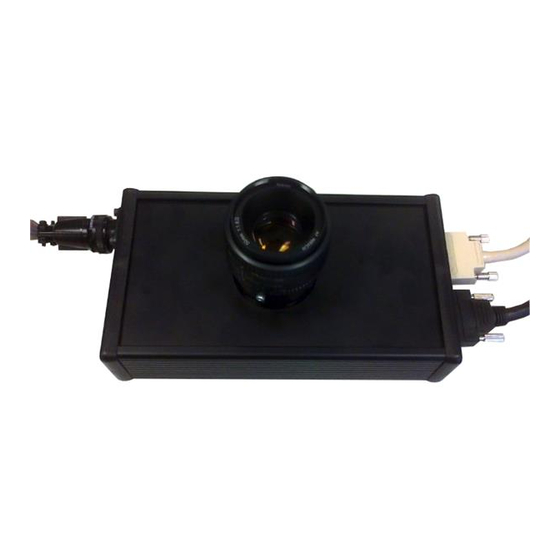
CHR70M Version: v3 Evaluation System Manual Page 5 of 15 1.4 CHR70M BOARD 1.4.1 L ENS HOLDER The CHR70M PCB is equipped with a F-mount lens holder and lens. 1.4.2 S ENSOR POWER AND BIASING This part of the test board includes the sensor, its power sources and biasing (decoupling to ground). Below you can see the demo system. -
Page 7: Frame Grabber And Pc
CHR70M Version: v3 Evaluation System Manual Page 6 of 15 RAME GRABBER AND A frame grabber card which can accept the Medium and Full CameraLink interface was chosen to complete the test system interface. The NI PCIe-1433 allows raw image data to be dumped at 4.8Gbit/s on the PC. This card is fitted in a PCI Express slot of the test system PC and uses two dedicated cables to connect to the CHR70M board. -
Page 8: Installing The System
CHR70M Version: v3 Evaluation System Manual Page 7 of 15 NSTALLING THE SYSTEM When installing the system, the following connections have to be made: 1. Connect the PC to its peripherals (keyboard, mouse and monitor) and power up. 2. Connect the demo board to a power supply (+5V/+12V/-12V). Their individual grounds are connected on the board. -
Page 9: Running The System
CHR70M Version: v3 Evaluation System Manual Page 8 of 15 UNNING THE SYSTEM 4.1 S OFTWARE OVERVIEW Next figure shows a screenshot of the demo software. The four main areas of the software are: 1. Control area: The user can control the software (grab frames, save and load configuration files …) via a number of push buttons. -
Page 10: Software Details
CHR70M Version: v3 Evaluation System Manual Page 9 of 15 4.2 S OFTWARE DETAILS 4.2.1 C ONTROL AREA The 10 controls in the Control Area are: 1. STOP APPLICATION button: Click this button to stop the application from running and exit to the labview run- time environment. -
Page 11: Register Settings Area
CHR70M Version: v3 Evaluation System Manual Page 10 of 15 CONTINOUS button to start the calibration loop. After it is done, you click this button again to stop the calibration. See further for more details. 10. INFO TEXT BOX: Containing info about the configuration file Note: On the Desktop of the evaluation PC, there are two configuration files;... -
Page 12: Image Area
CHR70M Version: v3 Evaluation System Manual Page 11 of 15 Every register setting in this list refers to a sensor register (see data sheet for complete register map). The user of the evaluation system can only change the ‘value’ of the registers. The other entries are informational. (Tip: the register addresses (third column from the right) match the address values in the register map in the datasheet). -
Page 13: Image Statistics Area
CHR70M Version: v3 Evaluation System Manual Page 12 of 15 4.2.4 I MAGE STATISTICS AREA Next figure shows the image statistics area. The ‘image statistics area’ consists of: 1. SAVE BUTTONS: Clicking these buttons will save the requested image(s) in a specific file format. Set the path and name and the software will automatically add the frame number per image. -
Page 14: Column Offset Calibration
CHR70M Version: v3 Evaluation System Manual Page 13 of 15 4.4 C OLUMN FFSET ALIBRATION Because the offsets of the different channels can be different (and also the offsets of the PCB ADC's) it is recommended to change the offset registers of every channel until an even image is received. Manually adjusting these registers can be difficult, that is why the software provides an automatic calibration for this. - Page 15 CHR70M Version: v3 Evaluation System Manual Page 14 of 15 FIGURE 1: BEFORE CALIBRATION FIGURE 2: AFTER CALIBRATION © 2014 CMOSIS bvba...
-
Page 16: Subsampling
CHR70M Version: v3 Evaluation System Manual Page 15 of 15 FIGURE 3: LOWERED THE OFFSET OF 1 CHANNEL FIGURE 4: LOWERED ALL OTHER CHANNELS 4.5 S UBSAMPLING When you want to enable subsampling with the internal sequencer, set the sensor register CHR70M_sub_y to 1. Then on the Timing Config tab, set the Subsampling register to 8.
Need help?
Do you have a question about the CMOSIS CHR70M and is the answer not in the manual?
Questions and answers