
Related Manuals for Festo CPX-AP-I-4DI4DO-M12-5P


Summary of Contents for Festo CPX-AP-I-4DI4DO-M12-5P
- Page 1 CPX-AP-I-4DI4DO-M12-5P Digital input/output module Operating instruc- tions 8170509 2022-03a [8170511]...
- Page 2 Translation of the original instructions...
-
Page 3: Table Of Contents
Technical data..............19 Festo — CPX-AP-I-4DI4DO-M12-5P — 2022-03a... -
Page 4: About This Document
Scanning the printed Data Matrix Code with an appropriate device opens the Festo Support Portal with the information appropriate for the product. Alternatively, the Product Key (11-digit alphanumeric code on the product labelling) can be entered in the search field of the Support Portal è... -
Page 5: Safety
UL inspection mark on the product is also applicable to ensure compliance with the certification conditions of Underwriters Laboratories Inc. (UL) for USA and Canada è 1.1 Applicable documents. Additional information – Contact the regional Festo contact if you have technical problems è www.festo.com. – Accessories è www.festo.com/catalogue. Product overview Function The module supplies four digital inputs and four digital outputs in an automation system CPX-AP. -
Page 6: Digital Outputs
The electronic fuse of the module is slow-blowing. Electrical consumers with a temporarily higher current requirement can therefore also be connected. Festo — CPX-AP-I-4DI4DO-M12-5P — 2022-03a... -
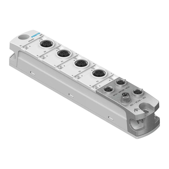
Page 7: Structure
Connection for power supply [XD1] Mounting interface connection side bottom and functional earth FE connection Mounting interface, lateral bottom and con- nection for functional earth FE Inscription label (optional) Mounting interface, lateral top Fig. 1: Product design Festo — CPX-AP-I-4DI4DO-M12-5P — 2022-03a... -
Page 8: Led Displays
Status/diagnostics for output 2 [X3.2] (red, yellow) Status/diagnostics for output 0 [X2.0] (red, yellow) Status of input 2 [X1.2] (green) Status of input 0 [X0.0] (green) Status/diagnostics for load supply [PL] (green, red) Fig. 2: LED displays Festo — CPX-AP-I-4DI4DO-M12-5P — 2022-03a... -
Page 9: Connecting Elements
Tab. 5: Connection for voltage forwarding Connection for system communication [XF10] Socket M8, 4-pin, D-coded Signal TX– Transmitted data – Received data + Transmitted data + RX– Received data – Tab. 6: Connection for system communication Festo — CPX-AP-I-4DI4DO-M12-5P — 2022-03a... -
Page 10: Assembly
If there is a connection to other circuits at one of the connections for inputs or outputs, the circuits must also comply with SELV/PELV. Assembly • Carry out assembly according to the automation system CPX-AP-I operating instructions è 1.1 Applicable documents. Festo — CPX-AP-I-4DI4DO-M12-5P — 2022-03a... -
Page 11: Installation
è Instruction manual for automation system CPX-AP-I è 1.1 Applicable documents è 9 Diagnostics and fault clearance Parameterisation Various parameters are available for reading out information about the modules in an automation system CPX-AP and adapting the modules to the application situation. Festo — CPX-AP-I-4DI4DO-M12-5P — 2022-03a... - Page 12 Current measured value of logic supply UINT16 – PS [mV] 20088 Current measured value of load supply UINT16 – PL [mV] 20093 Hardware version UINT8 – 1) ro = read only; rw = read write Tab. 12: AP parameter Festo — CPX-AP-I-4DI4DO-M12-5P — 2022-03a...
-
Page 13: Diagnostics And Fault Clearance
02 | 01 | 0105 Undervoltage in load Undervoltage in load supply (PL) 24 V DC (33620229) supply (PL) 24 V DC – Check power supply (load) Remedy – Check for short circuit. Festo — CPX-AP-I-4DI4DO-M12-5P — 2022-03a... - Page 14 – Check wiring. Diag- Error nostic status 08 | 01 | 01A2 Device in System The system initialization (module recognition) failed. The (134283682) State Emergency system is in maintenance mode. No I/O function is avail- Operation able. Festo — CPX-AP-I-4DI4DO-M12-5P — 2022-03a...
- Page 15 Description – Restart system 08 | 01 | 01A2 Device in System Remedy – Update firmware to latest version (134283682) State Emergency – Contact Festo service Operation Diag- Error nostic status Tab. 13: Diagnostic messages Festo — CPX-AP-I-4DI4DO-M12-5P — 2022-03a...
-
Page 16: Led Displays
PL red light Module ramp-up not yet completed. – System communication not yet initial- ised. fast red flashing Module identification (service function) – fast green flashing Tab. 14: LED module diagnostics [MD] Festo — CPX-AP-I-4DI4DO-M12-5P — 2022-03a... - Page 17 Short circuit/overload at output Check the connected actuators, elimi- nate short circuit/overload. To acknowledge the error after correcting the malfunction, reset the output. No channel error at output – Tab. 17: LED diagnostics of output Festo — CPX-AP-I-4DI4DO-M12-5P — 2022-03a...
- Page 18 Load supply PL not available. Check load supply PL. flashing green 0.5 Hz Load supply PL outside the tolerance Check load supply PL. range. flashing red 0.5 Hz Tab. 18: LED load supply [PL] Festo — CPX-AP-I-4DI4DO-M12-5P — 2022-03a...
-
Page 19: Technical Data
By the use of SELV/PELV circuits shock (protection against (safe extra-low voltage/protected extra-low voltage) direct and indirect con- tact in accordance with IEC 61010-1) Electromagnetic compati- See declaration of conformity è www.festo.com/sp bility Mounting position Tab. 19: General technical data Festo — CPX-AP-I-4DI4DO-M12-5P — 2022-03a... - Page 20 Capacitive load at load supply PL 24 V PL to 0 V PL [nF] Typically 45 24 V PL to FE [nF] Typically 35 0 V PL to FE [nF] Typically 20 Tab. 20: Power supply Festo — CPX-AP-I-4DI4DO-M12-5P — 2022-03a...
- Page 21 0 V SEN external and 0 V SEN internal Sensor power supply short circuit protection Short-circuit protection Electronic > 1.8 Trigger level Characteristic Slow-blowing Response after end of over- Automatic recovery load Tab. 21: Digital inputs Festo — CPX-AP-I-4DI4DO-M12-5P — 2022-03a...
- Page 22 Response after end of over- No automatic recovery load Output delay with resistive load Signal change from 0 to 1 [µs] . 200 Signal change from 1 to 0 [µs] . 200 Tab. 22: Digital outputs Festo — CPX-AP-I-4DI4DO-M12-5P — 2022-03a...
- Page 24 Copyright: Festo SE & Co. KG 73734 Esslingen Ruiter Straße 82 Deutschland Phone: +49 711 347-0 Internet: © 2022 all rights reserved to Festo SE & Co. KG www.festo.com...
Need help?
Do you have a question about the CPX-AP-I-4DI4DO-M12-5P and is the answer not in the manual?
Questions and answers