Table of Contents
Advertisement
Quick Links
Operating instructions
Chlorine Dioxide Systems
Bello Zon
Type CDEa
®
Please carefully read these operating instructions before use. · Do not discard.
The operator shall be liable for any damage caused by installation or operating errors.
The latest version of the operating instructions are available on our homepage.
Part no. 984883
Original operating instructions (2006/42/EC)
BA BEZ 043 01/14 EN
Advertisement
Table of Contents

Subscribe to Our Youtube Channel
Related Manuals for ProMinent ProMaqua Bello Zon CDEa 45


Summary of Contents for ProMinent ProMaqua Bello Zon CDEa 45
- Page 1 Operating instructions Chlorine Dioxide Systems Bello Zon Type CDEa ® Please carefully read these operating instructions before use. · Do not discard. The operator shall be liable for any damage caused by installation or operating errors. The latest version of the operating instructions are available on our homepage. Part no.
- Page 2 Supplemental directives Supplementary information Read the following supplementary information in its entirety! Should you already know this information, you will benefit more from referring to the operating instructions. The following are highlighted separately in the document: Enumerated lists Fig. 1: Please read! - refer to...
-
Page 3: Table Of Contents
Table of contents Table of contents Product identification CDEa..........6 About this system..............7 Safety chapter............... 8 Storage and Transport............14 Requirements relating to the installation location....15 Assembly................16 Installation................19 7.1 Installation, hydraulic..........19 7.1.1 Bypass line.............. 21 7.1.2 Safety equipment bypass line........ - Page 4 Table of contents 11.3.7 Calibrating pumps..........44 11.3.8 Final start up............44 11.4 Testing the safety equipment........45 11.5 Installation of the chemical canisters......45 11.6 Checking ClO production........46 Operation................47 12.1 Replacing chemical canisters........47 12.2 Bleeding pumps............49 12.3 Setting the Flow Control dosing monitors....
-
Page 5: Product Identification Cdea
Product identification CDEa Product identification CDEa Type Max. ClO output Part no. CDEa 45 45 g/h 1047456 CDEa 80 80 g/h 1047457 CDEa 140 140 g/h 1047458... -
Page 6: About This System
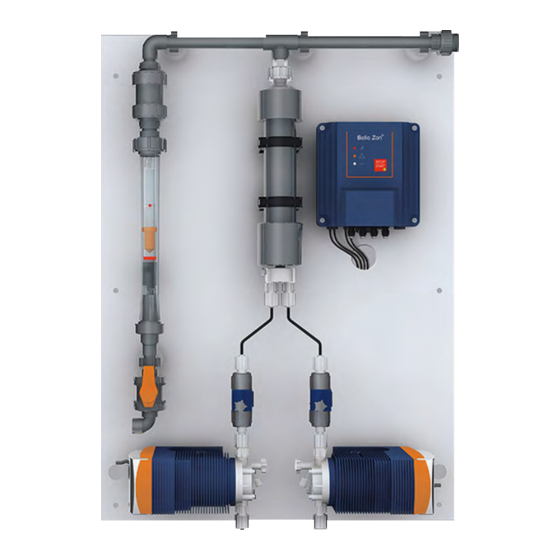
About this system About this system Connection-ready complete Bello Zon CDEa chlorine dioxide sys‐ ® tems are used in the continuous production and metering of 5 to 200 g of chlorine dioxide per hour with diluted chemicals. The system is winning over customers, thanks to its simple operation and clearly laid out construction. -
Page 7: Safety Chapter
Safety chapter Safety chapter Labelling of safety notes The following signal words are used in these operating instructions to denote different levels of danger: Identification of safety notes The following signal words are used in these operating instructions to denote different severities of danger: Signal word Meaning DANGER... - Page 8 Safety chapter Intended use The Bello Zon ® CDEa system is intended solely for producing a disinfectant solution containing ClO from dilute hydrochloric acid (9 %) and sodium chlorite solution (7.5 %) and for metering it into a bypass line together with water. Any other uses or modifications to the system are prohibited! Die Bello Zon ®...
- Page 9 Service Service refers to service technicians, who have received proven training and have been authorised by ProMinent to work on the system. Safety equipment The safety equipment available and how it is tested, is contained in the "Start up"...
- Page 10 Safety chapter WARNING! Danger due to hazardous ClO Under rare fault conditions toxic ClO solution and gas can escape via a leak. – A gas detector should be installed if no other measure is provided to ensure personnel safety in the event of ClO escaping.
- Page 11 Safety chapter Personal protective equipment Face mask Rubber or plastic boots Protective gloves (ClO -resistant type!) Protective apron Full-face protective mask 1 replacement filter per protective mask WARNING! The required type and configuration of personal protective equipment may vary from country to country and change over time.
- Page 12 Safety chapter WARNING! The required information for the emergency may vary from country to country and change over time. Sound pressure level Sound pressure level LpA < 70 dB according to EN ISO 20361 at maximum stroke length, maximum stroke rate, maximum back pressure (water)
-
Page 13: Storage And Transport
Declaration is submitted that has been completed correctly and in full by an authorised and qualified person on behalf of the operator. The "Decontamination Declaration" can be found in the Appendix or at www.prominent.com/en/down‐ loads. WARNING! Ensure that the system is thoroughly rinsed through before moving or transporting it - see "Decommissioning"... -
Page 14: Requirements Relating To The Installation Location
Requirements relating to the installation location Requirements relating to the installation location Safety notes CAUTION! Warning against illegal operation Observe the regulations that apply where the device is installed. Requirements relating to the chlorine Do not locate the chlorine dioxide system outdoors. dioxide system installation site Provision should be made for protecting the chlorine dioxide system against unauthorised access. -
Page 15: Assembly
Assembly Assembly Safety notes WARNING! Danger due to the sudden unexpected escape of hazardous chlorine dioxide solution The seals, which are exposed to chlorine dioxide solution, will start to leak if they are not replaced early enough. – Set up the system so that it can be accessed easily for maintenance. - Page 16 Assembly 9-11,5 P_PMA_BEZ_0135_SW Fig. 2: Fixing plate Rawlplug Hanger bolt Spacer Hexagon nut Washer (metal) Protective cap Warning labels CAUTION! Warning against illegal operation Observe the regulations that apply where the device is installed. Provided national regulations do not require otherwise, use signs with the shape and type given below.
- Page 17 Assembly Warning sign * Warning label * Included text Sodium chlorite Sodium chlorite NaCIO NaClO P_BEZ_0003_SW * Mandatory in Germany c) Attach this sign in rooms in which sodium chlorite is handled: Warning label * Included text Do not interchange storage Do not use storage tank tanks and devices.
-
Page 18: Installation
Take appropriate measures to ensure the bypass line of the Bello Zon ® system is not placed under vacuum pressure (for example install a ProMinent flushing valve with venting mechanism). – Take appropriate measures to ensure that the bypass line of the Bello Zon system is always ®... - Page 19 Installation Additional safety fittings Flow generator bypass line Point of injection Flushing equipment with vacuum relief valve Suction lance and level switch for dilute acid Installation examples Installation example A P_PMA_BEZ_0137_SW Fig. 4: Installation example A: the reactor outlet valve (7) of the Bello Zon system is located beneath the ®...
-
Page 20: Bypass Line
Installation Installation example B P_PMA_BEZ_0138_SW Fig. 5: Installation example B: the reactor outlet valve (7) of the Bello Zon ® system is located above the point of injection (9): Back pressure valve (16) and vent valve (8) required in the bypass line. 7.1.1 Bypass line DANGER! Warning of hazardous chlorine dioxide vapours... -
Page 21: Safety Equipment Bypass Line
Installation WARNING! Warning of hazardous chlorine dioxide vapours Hazardous chlorine dioxide vapours can escape through a leaking bypass line. Some threaded con‐ nectors are loosened in the factory prior to trans‐ port. – Check whether all threaded connectors on the bypass line on the bracket are correctly tight‐... - Page 22 Installation WARNING! Risk of explosion in the bypass line If the dosing remains switched on when there is no water flow, it can then lead to an unacceptably high concentration of chlorine dioxide in the bypass line. If additionally the bypass line is not completely full with water, a critical gas phase can form, resulting in an explosion in the bypass line.
-
Page 23: Flushing Equipment With Vacuum Relief Valve (Accessory)
Installation Bypass line specifications for CDEa Data Value Unit Nominal width DN20 Diameter 25 mm Operating pressure, min. 1.5 bar Operating pressure, max. 8 bar Pressure rating* PN16 Flow 350 ... 1000 l/h * with PVC lines There is a specific risk of a vacuum being generated especially when the water is stationary if: The flow direction reverses in the main water supply pipe (with a large diameter) - non-return valves are never 100 % water‐... -
Page 24: Back Pressure Valve (Accessory)
Installation WARNING! Hazardous ClO solution can escape – Prevent the flushing valve from being opened unintentionally, e.g. using a cable connector or a padlock. WARNING! Outgassing ClO solution can still vaporize in the bypass line With Bello Zon ® systems that are ordered without a bypass line, a flow control and a rinse valve with a vacuum relief valve must be installed that are tech‐... -
Page 25: Protective Filter (Accessory)
Installation 7.1.7 Protective filter (accessory) Fit a protective filter upstream if solid particles are present in the bypass water. 7.1.8 Chlorine dioxide detection kit (accessory) The DPD method can be used simply and reliably to determine the concentration of chlorine dioxide. An appropriate photometer is available for this purpose. -
Page 26: Installation, Electrical
Pull briefly on the suction hose (5) and tighten up the union nut (4). The bleed hose of the corresponding pump can be inserted into the head of the suction lance with ProMinent suction lances, returning the feed chemical cleanly when the pump is bled. -
Page 27: Connecting The Level Switch
Installation 7.2.1 Connecting the level switch Connect the round plug for the acid suction lance (level switch) to the "Level" input on the left pump. Connect the round plug for the chlorite suction lance (level switch) to the "Level" input on the right pump. 7.2.2 Wiring the system's control box Loosen the 4 screws on the housing and place the front part in the parked position. - Page 28 Installation B0591 Fig. 8: Threaded connector for mains cable (M20 x 1.5) Threaded connector M20 x 1.5 Thrust collar M20 Thrust collar M20 Dummy washer M20 7.2.2.1 Connecting the terminals Ä Further information Remove the cable insulation as per on page 28 and crimp on the corresponding cable end sleeves.
-
Page 29: Installing An Emergency Stop Switch
CAUTION! Warning against illegal operation Observe the regulations that apply where the device is installed. - - - The chlorine dioxide system is now sufficiently prepared that it can be started up by a ProMinent service technician! - - -... -
Page 30: System Overview
System overview System overview P_PMA_BEZ_0139_SW Fig. 10: CDEa Reactor outlet valve Non-return valve for bypass line Reactor Flow meter Reactor input valve, acid Dosing monitor, acid Stopcock, bypass line Bleed valve, acid Metering pump, acid Bracket Control box not shown Danger signs not shown CDV fitting kit For the sake of clarity, only parts of the acid metering line have been shown. -
Page 31: Functional Description
Functional description Functional description 9.1 Chemical principle of the systems Bello Zon ® chlorine dioxide systems work according to the hydro‐ chloric acid-chlorite process: Bello Zon ® CDEa systems produce a 2 % chlorine dioxide solution (20 g/l ClO ) by combining dilute hydrochloric acid and dilute sodium chlorite solution. -
Page 32: Safety Equipment
Functional description P_PMA_BEZ_0066_SW Fig. 11: Hydraulic drawing CDEa in bypass operation Water to be treated 11 Acid Bypass 12 Chlorite Reactor 13 Safety collecting pans, recommended (acces‐ Reactor outlet valve sory) Flushing equipment with vacuum relief valve, 19 Bypass pump (accessory) recommended (accessory) 20 Flow meter Water to be treated... -
Page 33: Control Elements
Functional description 9.4 Control elements P_PMA_BEZ_0134_SW Fig. 12: The control elements [START/STOP] key with green "Operation" LED Alarm LED, red Warning LED, yellow Pause LED, white [START/STOP] key [START/STOP] key can be used to start and stop the two metering pumps. LEDs Name Colour... -
Page 34: Set Up
Set up Set up This chapter describes the parts of the software needed for the two metering pumps. The entire software is described in the enclosed "Operating Instructions for Solenoid Metering Pumps gamma/ L". The "Start Up" chapter describes the settings relating to start up. The pumps have to be adjusted accordingly if other settings are needed over and above the factory settings or a replacement pump needs to be used. -
Page 35: Calibrate Pumps (Calib Menu)
Set up 10.1 Calibrate pumps (CALIB menu) Continuous display B0093 Fig. 14 The two metering pumps have to be calibrated when starting up or following the replacement of a diaphragm. If the stroke length is changed by more than ±10 scale divisions, the yellow warning light lights up, the continuous display flashes „Calib“... -
Page 36: Manual" Operating Mode
Set up Determine the required metering volume (difference between initial volume - remaining volume). Enter this amount under the next menu option and then press [P] to move to the next menu option. „UNIT“ , use the [arrow key] to select the Under menu option „L“... -
Page 37: Contact" Operating Mode
Set up 10.3 "Contact" operating mode For "Contact conc" control mode (via a water meter) 000.0 000.0 000.0 000.0 Contact CONC 000.0 000.0 001.0 009.0 Contact interval 0 0.0 000. 0 4.0 009. Mass concentration 000. KG/L 000. Mass density Continuous display P_PMA_BEZ_0130_SW... -
Page 38: Analog" Operating Mode
Set up The first menu item displays the unit of measure for the con‐ „L/P“ ; the unit of measure for the tact interval spacing ( „UNIT“ ). volume was determined during calibration via Enter the contact interval for the water meter. „% by weight“... -
Page 39: Start Up
Carefully read through this entire chapter prior to start up. – Only have initial commissioning performed by a Service team authorised by ProMinent . – The Service team authorised by ProMinent should instruct the operating and maintenance personnel during start up. -
Page 40: Installation - Final Steps
Start up Note for the system operator During start up, also adhere to the instructions in the following reg‐ ulations: a) - Accident Prevention Regulations (in Germany: GUV 8.15 or VGB 65): Only start up chlorination systems after they have been checked by a technical expert to ensure they are in cor‐... -
Page 41: Analog" Control Mode (Via 0/4-20 Ma Signal)
The hose from a bleed connector can be inserted into the head of the corresponding suction lance with ProMinent suction lances. Remove the cable connector from the hood of the metering pump. Place each suction lance in its own bucket full of clean water. -
Page 42: Filling The Reactor
Start up CAUTION! The hood of each pump has to be connected to the housing with a cable connector (plastic o-rings) to ensure that no one tampers with the pump during operation. 11.3.4 Filling the reactor WARNING! System components can rupture If the downstream valves are not open when the reactor is filled, the pressure of the metering pumps can cause the reactor to rupture. -
Page 43: Calibrating Pumps
Start up Remove the dosing monitor cable from the metering pump (to temporarily disable the dosing monitor). Turn the rotary dial fully to the left ("-"). Enter the required operating pressure on the discharge line. Re-insert the dosing monitoring cable. „Flow“... -
Page 44: Testing The Safety Equipment
Start up 11.4 Testing the safety equipment Safety collecting pans (accessories) Remove the intact storage tank from the dry safety collecting pan. Fill the safety collecting pan with water up to the edge and inspect for leaks. Acid and chlorite level switches Slowly withdraw the acid suction lance from the filled storage tank. -
Page 45: Checking Clo Production
Start up Immerse the right suction lance in the chlorite chemical can‐ ister. Does the foot valve float just above the base of the chemical canister? Tighten the screw lid. The temperature of the chemicals should always remain below 35 °C. 11.6 Checking ClO production... -
Page 46: Operation
Operation Operation WARNING! Risk of explosion due to ClO Together the two components, hydrochloric acid (HCl) and sodium chlorite (NaClO ), almost instan‐ taneously form large quantities of toxic ClO gas, which can also decompose in an explosive manner. – The two components, hydrochloric acid (HCl) and sodium chlorite (NaClO ) should never be... - Page 47 Operation WARNING! Warning of hazardous ClO Large volumes of hazardous ClO gas can be pro‐ duced, if the chemical canisters are not handled correctly. – Only allow trained personnel to change the chemical canisters. – Observe the colour code: Red stands for acid (HCl, left), Blue for chlorite (NaClO , right).
-
Page 48: Bleeding Pumps
The bleed hose from a bleed connector can be inserted into the head of the corresponding suction lance with ProMinent suction lances. Note the stroke lengths of the pumps. Set the stroke lengths of the pumps 100%. Place each suction lance in its own bucket full of clean water. -
Page 49: Setting The Flow Control Dosing Monitors
Operation Close the bleed valve, by turning in a clockwise direction. Repeat these steps on the chlorite pump. Set the recorded stroke lengths on the pumps. CAUTION! The hood of each pump has to be connected to the housing with a cable connector (plastic o-rings) to ensure that no one tampers with the pump during operation. -
Page 50: What Happens In The Event Of Incorrect Operation
What happens in the event of incorrect operation? What happens in the event of incorrect operation? a) Chemical canisters Incorrect operation: Chemical canisters have been swapped. Consequence: Toxic ClO gas is formed in the chemical lines and chemical canisters. Incorrect operation: Incorrect chemicals or the incorrect concentration or purity of chemical have been used and the Bello Zon system / pumps have started up. -
Page 51: Maintenance
Maintenance Maintenance Safety notes WARNING! Hazardous ClO can escape If maintenance is forgone or neglected, in the worst case ClO solution could escape through a pipe leak. – Service should service the Bello Zon ® system at least annually. WARNING! Chemicals can escape Hazardous chemicals in the system's hydraulic components. -
Page 52: Service Work By The Service Team
Service work by the Service team Interval Maintenance work Personnel After 6 months, at Replace all wear parts - ProMinent service kit! Customer Service least annually department With older systems, check the pipe walls of the bypass line for limescale. - Page 53 Maintenance Order numbers for maintenance kits Complete maintenance kit for 1-yearly 3-yearly CDEa 45 1047804 1047807 CDEa 80 1047805 1047808 CDEa 140 1047806 1047809...
-
Page 54: Repairs
Repairs Repairs WARNING! The reactor can explode If unauthorised repair work is carried out, the worst case scenario is a reactor explosion. – Only Customer Service may repair the Bello ® system. -
Page 55: Troubleshooting
– If the green "Operation" LED is Off, then the control does not actuate the pumps and ignores all input signals. If you wish to contact ProMinent because of a – fault, then previously e-mail the following details: Order number –... -
Page 56: Functional Faults With Led Signals On Control Box
Troubleshooting 16.2 Functional faults with LED signals on control box Fault description Cause Remedy Personnel Red "Fault" LED lights A chemical canister is Replace both chemical canisters - Instructed per‐ empty. refer to the "Operation" chapter. sonnel Problem with a metering Read the error message on the Technical pump. - Page 57 – Only use the approved original fuses from Ä Chapter 16.4 „Replacing the ProMinent, see mains fuse box“ on page 56 . Only in rare cases will any other fuse, with the values given below, have exactly the same properties.
-
Page 58: Decommissioning
Decommissioning Decommissioning WARNING! Risk of explosion due to ClO The two components, hydrochloric acid (HCl) and sodium chlorite (NaClO ) almost instantaneously form large quantities of hazardous ClO gas, which can also decompose in an explosive manner. – Never pour the contents of the chemical canis‐ ters together. -
Page 59: Over Longer Periods
Decommissioning CAUTION! Warning of incorrect metering The ClO in the reactor decomposes within a few hours (due to its high concentration). Therefore, after switching back on, the system temporarily meters less ClO – Bear this in mind when switching back on. –... - Page 60 Decommissioning Special tool: Approx: 3 m of hose with webbing, d 19/27 mm, soft PVC #37041 pH measuring instrument pH indicator paper, although it is bleached by ClO Neutralising storage tank - see "Dilution volume" table: It should exceed this volume.
-
Page 61: Disposal
Declaration is submitted that has been completed correctly and in full by an authorised and qualified person on behalf of the operator. The "Decontamination Declaration" can be found in the Appendix or at www.prominent.com/en/down‐ loads. WARNING! Danger from hazardous chemicals The Bello Zon ®... -
Page 62: Technical Data
Technical data Technical data System Type Chlorine dioxide capacity* Max. operating Max. priming Dimensions # pressure lift of metering pumps** min.-max./hour min./day HxWxD CDEa 45 5 ... 45 7 / 8** 958x700x195 CDEa 80 8 ... 80 7 / 8** 958x700x195 CDEa 140 14 ... - Page 63 Technical data Variable Value Comment Degree of pro‐ IP 54 Minimum protection for tection: components. Only applies to the control if the seal is cor‐ rectly fitted. Miscellaneous: Protect against: Direct sunlight IR radiation (also strong heat sources) UV radiation Ionising radiation Control box Power supply (XP1)
- Page 64 Technical data Active standard signal 0/4...20 mA) Specification Value Unit (XE2): Input apparent ohmic resistance, Ω approx. The metering pumps make their first metering stroke at approx. 0.4 mA (4.4 mA) and enter into continuous operation at approx. 19.6 External pause (XE1): Specification Value Unit...
-
Page 65: Dimension Sheet
Dimension sheet Dimension sheet Dimension sheet for CDEa Fig. 16: Dimensions in mm CDEa 45 CDEa 80 CDEa 140 1177 533.5... -
Page 66: Ordering Information
Ordering Information Ordering Information Suction lances Accessories suitable for system types Part no. Suction lance for connection to disposable storage tanks CDEa 45 ... 80 802077 5 ... 60 litre with 2 m long suction hose 6/4 mm Suction lance for connection to disposable storage tanks CDEa 140 802078 5 ... - Page 67 Ordering Information Flushing equipment with vacuum Flushing equipment complete with vacuum relief valve installed in relief valve the bypass line downstream of the Bello Zon ® system helps to keep the reactor at atmospheric pressure and enable it to be filled safely when starting up and enable it to be safely rinsed and emp‐...
- Page 68 Ordering Information Protective filter (accessory) Fit a protective filter upstream if solid particles are present in the bypass water. Accessories Part no. 791547 DULCOFILT ® protective filter G1", mesh size 100 µm Emergency stop switch Accessories Part no. Emergency stop switch 700560 Gas detector GMA 36 for chlorine The GMA 36 chlorine dioxide gas detector is designed as a com‐...
- Page 69 Ordering Information Consider the bypass flow required when selecting a suitable bypass pump. The following flow data is recommended for the dif‐ ferent systems: System types Bypass line Diameter Flow m³/h CDEa 45 - 140 DN 25 0.1 ... 1.0 Use PVC as the material for the bypass.
-
Page 70: Wiring Diagram
Wiring diagram Wiring diagram INPUTS INTERNAL OUTPUTS XE3:1 Flow meter from the bypass XE3:2 XE12:1 Fault alert Acid pump XE12:2 XE11:1 Warning alert Acid pump XE11:2 XE22:1 Fault alert Chlorite pump XE22:2 Warning alert XE21:1 Chlorite pump XE21:2 XA1:1 XA1:2 External cable XA1:3 Acid pump... - Page 71 Wiring diagram Assignment of threaded connectors 5.1 5.2 P_PMA_BEZ_0132_SW Fig. 21: Assignment of threaded connectors for customers Cable Terminal Cable use Threaded Number Leads per Ø cable min. - feed- connector of cables cable max. through Mains voltage input 4.5 ... 10 XR1 / XR2 Warning contact output 3.5 ...
-
Page 72: Ec Declaration Of Conformity For Machinery
In accordance with DIRECTIVE 2006/42/EC OF THE EUROPEAN PARLIAMENT AND OF THE COUNCIL, Appendix I, BASIC HEALTH AND SAFETY REQUIREMENTS, section 1.7.4.2. C. ProMinent GmbH Im Schuhmachergewann 5 - 11 D - 69123 Heidelberg, hereby declare that the product specified in the following, complies... -
Page 73: Chlorine Dioxide Hazardous Substance Data Sheet
Chlorine dioxide hazardous substance data sheet Chlorine dioxide hazardous substance data sheet (The text is based on the hazardous substances data sheet issued by the Bundesvereinigung der Firmen im Gas- und Wasserfach e.V. FIGWA, 50968 Cologne, dated 16.4.1998.) Properties of chlorine dioxide and The chlorine dioxide solutions used for water treatment have a instructions for handling aqueous sol‐... -
Page 74: Handling Aqueous Chlorine Dioxide Solutions
Chlorine dioxide hazardous substance data sheet Chlorine dioxide is stable over several days as an aqueous dilute solution, provided the solution is pure and stored in the dark or if the temperature of the solution remains below 25 degrees C and its pH value is less than 7. -
Page 75: Personal Protective Equipment
Chlorine dioxide hazardous substance data sheet Odour threshold: The odour of chlorine dioxide gas is perceptible above a concen‐ tration of around 15 mg/m of air. 24.3.2 Personal protective equipment Respiratory protection: Gas mask, filter B/grey Eye protection: Safety goggles, face visor Hand protection: Rubber gloves Other:... - Page 76 Chlorine dioxide hazardous substance data sheet Note: The information is based on our state of knowledge at the time of these operating instructions going to print. It is intended to con‐ tribute to the safe handling of aqueous chlorine dioxide solution and, as such, does not have the purpose of ensuring certain prop‐...
-
Page 77: Index
Index Index Chlorine dioxide hazardous substance data 1, 2, 3 ... sheet ........73 "Analog"... - Page 78 Index Installation - final steps ....40 Product identification ..... . . 5 Installation examples .
- Page 79 Index Threaded connectors ..... 71 Transport ......13 Troubleshooting .
- Page 80 ProMinent GmbH Im Schuhmachergewann 5-11 69123 Heidelberg Germany Telephone: +49 6221 842-0 Fax: +49 6221 842-419 Email: info@prominent.com Internet: www.prominent.com Heidelberg, 2, en_GB © 2013...
Need help?
Do you have a question about the ProMaqua Bello Zon CDEa 45 and is the answer not in the manual?
Questions and answers