Table of Contents
Advertisement
Quick Links
Operating instructions
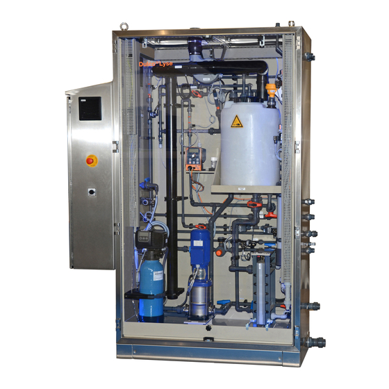
Chlorine electrolysis system
DULCOLyse
EN
P_PMA_ECA_0015_SW_2
Please carefully read these operating instructions before use. · Do not discard.
The operator shall be liable for any damage caused by installation or operating errors.
The latest version of the operating instructions are available on our homepage.
985179
Original operating instructions (2006/42/EC)
BA DZ 008 06/21 EN
Advertisement
Table of Contents

Related Manuals for ProMinent DULCOLyse


Summary of Contents for ProMinent DULCOLyse
- Page 1 Operating instructions Chlorine electrolysis system DULCOLyse P_PMA_ECA_0015_SW_2 Please carefully read these operating instructions before use. · Do not discard. The operator shall be liable for any damage caused by installation or operating errors. The latest version of the operating instructions are available on our homepage.
- Page 2 Supplemental directives General non-discriminatory approach In order to make it easier to read, this document uses the male form in grammatical structures but with an implied neutral sense. The document is always aimed equally at women, men and gender-neutral persons. We kindly ask readers for their under‐ standing in this simplification of the text.
-
Page 3: Table Of Contents
Table of contents Table of contents Description of the system............4 1.1 Components of the system........... 4 1.2 Description and operation..........5 1.2.1 Quality requirements of the feed water for DULCO‐ Lyse................8 Safety and responsibility............9 2.1 Labelling of Warning Information........9 2.2 User qualification............ -
Page 4: Description Of The System
Description of the system Description of the system The system is used for water disinfection in: F&B Brewery industry etc. The system is used to produce a chlorine-based disinfectant. 1.1 Components of the system P_PMA_ECA_0013_SW Fig. 1: Components of the system in the system cabinet B0667_2 Fig. -
Page 5: Description And Operation
Description of the system There is a stainless steel version of the system with a sealed con‐ trol cabinet (with doors): DULCO ® Lyse. There is a stainless steel version of the system, powder-coated, with clear PVC covers to [ open frame] . hang on: DULCO ®... - Page 6 Description of the system Fig. 3: Flowchart for DULCO Lyse ® Previous page Next page Chlorinsitu®-III 100-300 g/h Drawn by AvdB Mounting location: Glashorst 114 Date 9-12-2019 3925 BV Scherpenzeel Customer VDH Watertechnology As Built date Tel. +31(0)33-2778600 Poject Name Chlorinsitu®-III 100-300 g/h V1.00 Page...
- Page 7 Description of the system Component Function Water filter to combat impurities > 500 µm Softener softens the supply water Caustic metering pump Pump to correct the pH value Brine tank prepares and stores brine Membrane cell to produce chlorine and NaOH Refresh pipe helps to regenerate the anode Vacuum sensor...
-
Page 8: Quality Requirements Of The Feed Water For Dulcolyse
Degree of protection of the system: see nameplate. ture (IP) 1.2.1 Quality requirements of the feed water for DULCOLyse It is necessary to operate the system with feed water that meets certain minimum requirements for the safe and correct production of DULCOLyt. -
Page 9: Safety And Responsibility
Safety and responsibility Safety and responsibility 2.1 Labelling of Warning Information Introduction These operating instructions provide information on the technical data and functions of the product. These operating instructions pro‐ vide detailed warning information and are provided as clear step- by-step instructions. - Page 10 Safety and responsibility Type of information Hints on use and additional information. Source of the information. Additional measures. Denotes hints on use and other useful informa‐ – tion. It does not indicate a hazardous or dam‐ aging situation.
-
Page 11: User Qualification
Safety and responsibility 2.2 User qualification WARNING! Danger of injury with inadequately qualified per‐ sonnel The operator of the system / equipment is respon‐ sible for ensuring that the qualifications are ful‐ filled. If inadequately qualified personnel work on the unit or loiter in the hazard zone of the unit, this could result in dangers that could cause serious injuries and material damage. -
Page 12: General Safety Information
Safety and responsibility 2.3 General safety information WARNING! Danger due to hazardous substances By operating this system the operator generates hazardous substances. The operator is responsible for adapting the oper‐ ating instructions to their system in the event that more recent knowledge about the dangers associ‐ ated with a hazardous substance and its avoid‐... -
Page 13: Intended Use
Safety and responsibility Should you smell chlorine gas, safely and as quickly as pos‐ sible: – switch off the electrolysis system, – or press an Emergency Stop switch, – or disconnect the mains power supply, – or trigger an external fuse. –... -
Page 14: Storage And Transport
Storage and transport Storage and transport Storage Store the system in its original transport packaging in a sealed room, observing the following conditions: at a temperature of between 5 °C ... 50 °C at a relative air humidity below 85 % without condensation in a non-aggressive environment (no harmful vapours, chemi‐... -
Page 15: Preparation For Use
Preparation for use Preparation for use Adhere to all national and local regulations relating to the use of chlorine. The operator of the system is responsible for ensuring that the regulations are implemented. Ensure that the floor of the room has sufficient load-bearing capacity to bear the weight of the filled system. -
Page 16: Installation And Assembly
Installation and assembly Installation and assembly 5.1 Assembly check-list Assembly process Tick Check whether the assembly location complies with the guidelines governing tempera‐ ture, safety, space, humidity, etc. Clear the area in which the system is to be installed. Remove the plastic wrapping from the system. Check whether the system has suffered damage during transport or exhibits other damage. - Page 17 Installation and assembly Assembly process Tick Connect the transparent 8 mm nylon hose Ø10 mm between the "Brine softener" con‐ nector on the system and the Ø10 mm connector on the brine tank. Connect a Ø40 mm PVCU line to the brine tank and to the sewerage system as an over‐ flow line.
-
Page 18: Assembly And Installation Of The System
Installation and assembly 5.2 Assembly and installation of the system User qualification, mechanical/hydraulic installation: trained Ä Chapter 2.2 ‘User qualification’ and qualified personnel on page 11 User qualification, electrical installation: electrical technician Ä Chapter 2.2 ‘User qualification’ on page 11 CAUTION! Contamination and impurities in the lines can sub‐... - Page 19 Installation and assembly Fig. 4: Transport monitoring set Check whether the system has suffered damage during transport or exhibits other damage. Should you detect any damage, report it immediately to the freight forwarder and submit your claims. Check that the scope of delivery is complete. Check the transport monitoring set on the transport crate.
- Page 20 Installation and assembly Fig. 6: Screw feet Level the system horizontally. Use the screw feet shown here to do so. Fig. 7: Transport protection Remove the transport protection from within the system cab‐ inet. Remove the blanking plate on the vacuum sensor in the system cabinet.
- Page 21 Installation and assembly B0667_2 Fig. 8: DULCO Lyse system ® Separating tank K Brine tank Position the separating tank (J) in its intended position so that the pipework to the control cabinet can be run horizon‐ tally. Preferably position the separating tank in the direct vicinity of the system.
- Page 22 Installation and assembly B0954 Fig. 9: PVCU connector (Ø63 mm) Connect a PVCU pipe (Ø63 mm) to the PVCU connector (Ø63 mm) of the system and lead it outside. The pipe must initially rise a minimum of 1 metre upwards before the first bend is connected.
- Page 23 Installation and assembly B0955 Fig. 10: PVCU line (Ø20 mm) Lead the PVCU line (Ø20 mm) to the outside. B0952 Fig. 11: PVCU connector A PVCU connector (Ø20 mm) for the separating tank overflow to the waste water system B PVCU connector (Ø20 mm) "Fill separating tank" C PVCU connection (32 mm) "Process water"...
- Page 24 Installation and assembly B0673 Fig. 12: PVCU discharge line Ø50 mm Connect the Ø50 mm PVCU discharge line on the system to the sewerage channel. Connector Brine for membrane cell Refresh drainage line Fill brine tank Feed water line Brine for softener Fill separating tank Process water Drainage line...
- Page 25 Installation and assembly Connect a PVCU line (Ø20 mm) between the "Drain line" connector (8) on the system and the line to the waste water system. WARNING! Danger from chlorine gas – Connect this PVCU line directly to the building's waste water system. Do not route it into other lines.
- Page 26 Installation and assembly Connect a PVCU line (Ø20 mm) to the vent on the product tank to the outside. Fit the level switch for the product tank (included in the scope of delivery): remove the protective tube around the level switch.
- Page 27 Installation and assembly Cable Terminal brown 24 V DC X13 - 1 * white 0 V DC X13 - 2 * black X13 - 3 * * refer to the wiring diagram for terminal box X13 If necessary, use the terminal box provided to extend the cables.
- Page 28 Installation and assembly B0956 Fig. 17: Couplings 1. Coupling for "Brine softener" hose, transparent 2. "Brine membrane cell" PE coupling, blue 3. "Fill brine tank" PE coupling, red 4. "Brine tank overflow" coupling Use the black PE hose (Ø16 mm x 1.8 mm) from the brine tank to join the "Fill brine tank"...
- Page 29 Installation and assembly Fig. 19: Nylon coupling connectors Connect the transparent 8 mm nylon hose Ø10 mm between the "Brine softener" connector on the system and the Ø10 mm connector on the brine tank.
- Page 30 Installation and assembly Connect a Ø40 mm PVCU line to the brine tank and to the sewerage system as an overflow line. There should be salt in the brine tank once the PVCU lines have been connected. Connect the level switch of the brine tank: Connect the cables to terminal strip X1-4: The brown cable to the top row of the terminal strip The blue cable to the bottom row of the terminal strip.
- Page 31 Installation and assembly B0682 Fig. 20: Electrically install the system Electrically install the system: Connect the power cable of the system, as per the table below, to the terminal strip in the control cabinet, taking into account the rating values. Note the following when installing them: Make sure that the system is switched off when making or adjusting the electrical connections.
-
Page 32: Operation
Operation Operation Ä Chapter 2.2 User qualification, operation: instructed user ‘User qualification’ on page 11 Switch the system on by turning the main switch to "1". The main switch is on the control cabinet. 6.1 Touchscreen An overview of information and the control options available on the touchscreen are shown below. - Page 33 Operation Status Status 22.06.2021 14:45:56 A3355 +100 g/hour Serial number: Fig. 22: Status overview 22.06.2021 Brine tank + softener 14:57:58 Water hardness contact Regenerate contact Level low Regenerate brine flow meter Current pulses Valve, salt tank filling A3356 Current flow Softener brine valve Gramme Brine volume consumed...
-
Page 34: Menu Overview Of The Dulco ® Lyse
Operation 6.2 Menu overview of the DULCO ® Lyse Process Product Status Main menu (Display) overview storage tank storage tank Diaphragm cell Softener Power supply Separation storage tank Manual Operation operation Production Operating parameters settings Process water Calibrate pH flow Calibrate Language Touch screen... -
Page 35: Operating Principles
Operation 6.3 Operating principles You can adjust the values on the touchscreen regardless of the ‘Production Off’ , ‘Production On’ ). status of the system ( The current display closes after 5 minutes (software V1.07 and later). ‘Operating personnel’ password to access the Password You need the ‘Operation’... -
Page 36: Manual Operation
Operation Product storage tank 22.06.2021 15:01:56 Filling not allowed Level too high Time since the last production: Ultrasonic level sensor Volume Current signal Current level High product storage tank level Low product storage tank level Product to product storage tank Product to outlet A3357 Fig. -
Page 37: Commissioning
Commissioning Commissioning User qualification, preparation for commissioning/commis‐ Ä Chapter 2.2 ‘User qualifi‐ sioning: trained qualified personnel cation’ on page 11 INFORMATION!: The DULCO Lyse systems must be started up in ® the following order under the appropriate conditions. The system can only be safely started up, guarantee seamless operation and the warranty granted if this order is adhered to. - Page 38 Commissioning Preparation for commissioning Tick Check whether the hydrogen discharge line is connected in compliance with the reg‐ ulations. Check whether the vent lines for the product tank and system refresh pipe are con‐ nected and correctly routed outside. Check the drain connectors. Check the water supply.
- Page 39 Commissioning Preparation for commissioning Remaining points Remarks Take into consideration the remarks on this page and take appropriate action before commencing commis‐ sioning. THIS PART WAS ACCEPTED BY: NAME: SIGNATURE: Project number: System:...
-
Page 40: Check-List: Commissioning
Commissioning 7.2 Check-list: Commissioning Commissioning process for the DULCO ® Lyse Tab. 3: Commissioning check-list Step Check the system connectors, fuses and external connections of the product and brine tanks. Check that the hydrogen discharge conduit complies with the regulations and that the room is sufficiently ventilated. - Page 41 Commissioning Step Start a manual refresh on the display of the PLC. Check that there is a flow of lye during drainage. Check that the refresh valve and the vent valve are open. Check that the brine valve is open. Check that the brine flow corresponds to the setpoint.
-
Page 42: Commissioning Work
Commissioning 7.3 Commissioning work Ä Chapter 2.2 ‘User User qualification, commissioning: Service qualification’ on page 11 Prior to the start of commissioning, check that all preparations have been completed correctly. Commissioning is divided into two phases. Commissioning preparation is used to monitor the installa‐ tion phase and should be performed prior to commissioning. - Page 43 Commissioning Check the system connectors, fuses and external con‐ nections of the product and brine tanks. Check that the hydrogen discharge conduit complies with the regulations and that the room is sufficiently ventilated. ‘P&ID’ in the wiring Check that all lines comply with the diagram.
- Page 44 Commissioning Set the pressure in the water feed to 2 ... 2.5 bar. Use the test kit to measure the hardness of the supply water. The scope of delivery of the system includes a test kit for measuring the water hardness. Measure the hardness of the supply water upstream of the softener.
- Page 45 Commissioning Open the sampling tap for approx. 2 minutes and then take a sample. Use the test kit in "LOW RANGE" mode to measure the hard‐ ness of the softened water. Check whether the hardness of the softened water is 0°dH. [Regeneration] .
- Page 46 Commissioning 22.06.2021 Customer settings 15:03:42 Customer Lye temperature settings Brine tank filling time Maintenance Caustic tank filling time Time and date Delay time before the system switches off in response to the alert Min. “Product not to specification” Height of product storage tank Language menu Diameter of product storage tank Factory settings...
- Page 47 Commissioning Wear safety gloves. Use the measuring cup and the funnel to fill the caustic tank, remembering to wear gloves and safety glasses. Open the cap (1) of the caustic tank and pour lye into the tank. Fill the caustic tank with 33 % lye (5 litres). Use the cap to seal the caustic tank.
- Page 48 Commissioning Check that the brine flow corresponds to the setpoint. Checking that the booster pump is The booster pump should start up at the start of production starting up as soon as the liquid level in the separating tank has reached the right level.
- Page 49 Commissioning After 2 hours of production Measure the voltage at the membrane cell and check whether it corresponds to the basic settings list. At full system load, measure the current at the power supply and enter the values in the test log. Check the modem or internet connection, if available.
- Page 50 Commissioning Train the end user's personnel in the operation of the system. Draw the end user's attention to the fact that the system has to be maintained annually. Standard packages of spare parts are available for annual maintenance. Photograph the system and hand over the manual with the original test log to the customer.
-
Page 51: Alarm] / Troubleshooting Menu
[ALARM] / Troubleshooting menu [ALARM] / Troubleshooting menu Ä Chapter 2.2 User qualification, troubleshooting: Service ‘User qualification’ on page 11 WARNING! Hazardous chemicals can escape Hydrogen, sodium hydroxide and chlorine remain in the DULCO Lyse system even after operation. ® [On] in the –... -
Page 52: Error Messages
[ALARM] / Troubleshooting menu Tank is full System response: Production is switched off. Cause: The product tank is completely filled. No external signal System response: Production is switched off. Cause: There is no external enable signal. Anode refresh The system refreshes the brine in the anode. System response: Production is not switched off. -
Page 53: Power Supply
[ALARM] / Troubleshooting menu Causes: The vacuum sensor has a fault. The vent valve does not open. 8.2.2 Power supply Electric current too low The amperage measured during production is lower than the speci‐ fied minimum amperage for the delay time. System response: - see “A. -
Page 54: Product Tank
[ALARM] / Troubleshooting menu pH too low The pH value measured during production was lower than the specified minimum pH value for the delay time. System response: “A. System response at too low a value” Ä Chapter 8.2.9 ‘Response of the system’ on page 57 Causes: The pH value measurement is not correct. -
Page 55: Separating Tank
[ALARM] / Troubleshooting menu Causes: The liquid level sensor in the product tank is faulty. The liquid level sensor parameters are incorrect. The product tank settings are incorrect. An external cause results in liquid also entering the product tank. Retaining tank leak detection The sensor in the retaining tank of the product tank signals liquid present. -
Page 56: Membrane Cell
[ALARM] / Troubleshooting menu Water flow rate too high The water flow measured was higher than the specified maximum flow for the delay time. System response: - see “B. System response at too high a value” Ä Chapter 8.2.9 ‘Response of the system’ on page 57 Causes: The frequency converter is faulty. -
Page 57: Other Faults
[ALARM] / Troubleshooting menu Temperature cathode too high The temperature sensor on the cathode side of the membrane cell measures too high a temperature. System response: The system switches off. Causes: The cooling system is not working. The current and voltage are too high. The temperature switch is faulty. - Page 58 [ALARM] / Troubleshooting menu The system switches off completely if the value does not fall during the delay time. A reset is needed to restart the system.
-
Page 59: Checks And Preparation For Maintenance/Repair
Checks and preparation for maintenance/repair Checks and preparation for maintenance/repair Carry out maintenance as per the check-list supplied in the mainte‐ nance package! 9.1 Care of the Operating Unit User qualification, maintenance instructed personnel, see Ä Chapter 2.2 ‘User qualification’ on page 11 NOTICE! Damage caused by prohibited cleaning equipment or agents... -
Page 60: Repair
Checks and preparation for maintenance/repair Tab. 5: Maintenance kits PM order number vdH order number Maintenance kit 1041427 80200002 1-year maintenance kit for DULCO ® Lyse 100 ... 300 1041430 80200004 3-year maintenance kit for DULCO ® Lyse 100 ... 300 1044366 80200006 Spare parts kit for DULCO... -
Page 61: Disposal Of Used Parts
Refer to the Material Safety Data Sheet for your feed chemical. A current Declaration of Decontamination is available to download on the ProMinent website. Sign indicating EU collection system In accordance with the European Directive 2012/19/EU on waste electrical and electronic equipment, this device features the symbol showing a waste bin with a line through it. -
Page 62: Technical Data
Technical data Technical data Tab. 6: Technical data Parameter Unit Type Type Type Capacity per hour (h) Capacity per day (d) kg/d Dimensions LxWxH of frame 2225x610x1510 Space requirement 1800x1500 Transport weight Transport box 2815x1015x2340 Brine tank Recommended volume of the product tank 500 ... - Page 63 Technical data Parameter Unit Type Type Type *** Ambient air in the installation space: non-condensing, non-corrosive and dust-free **** PVCU pipework: maximum 10 metres in length with a maximum of 3 bends Electrical data Capacity of the system Internal fuse Operating voltage Capacity 100 (g/h)
-
Page 64: Eu Declaration Of Conformity
EU Declaration of Conformity EU Declaration of Conformity Insert the EU Declaration of Conformity here. -
Page 65: Calibrating The Ph Measurement
Calibrating the pH Measurement Calibrating the pH Measurement [Stop] button to switch off system production. Use the ‘Calibrate pH’ in the ‘Operation’ menu and press the Select green button with the tick in the message that appears. ð A solenoid valve isolates the line with the pH sensor from the power supply. -
Page 66: Index
Index Index 1, 2, 3 ... [ALARM] menu ......51 Height of level switch in product tank ..35 Access code . - Page 67 Index Refresh anodes ......36 Requirements regarding the installation place . . . 15 Reset ....... . . 32 Rinse .
- Page 68 Glashorst 114 3925 BV Scherpenzeel The Netherlands Telephone: ++31 (0)33-2778600 Email: info@vdhwater.nl Internet: www.vdhwater.nl 985179, 6, en_GB DTP and Design: ProMinent GmbH Im Schuhmachergewann 5-11 69123 Heidelberg, Germany Germany Telephone: +49 6221 842-0 Fax: +49 6221 842-419 Email: info@prominent.com Internet: www.prominent.com...
Need help?
Do you have a question about the DULCOLyse and is the answer not in the manual?
Questions and answers