Table of Contents
Advertisement
Quick Links
Operating instructions
Ozone generation system
OZONFILT
®
Please carefully read these operating instructions before use. · Do not discard.
The operator shall be liable for any damage caused by installation or operating errors.
The latest version of the operating instructions are available on our homepage.
Part no. 982470
type OZVb 1 - 4 A
Original operating instructions (2006/42/EC)
EN
BA OF 036 03/21 EN
Advertisement
Table of Contents

Related Manuals for ProMinent OZONFILT OZVb 1 A


Summary of Contents for ProMinent OZONFILT OZVb 1 A
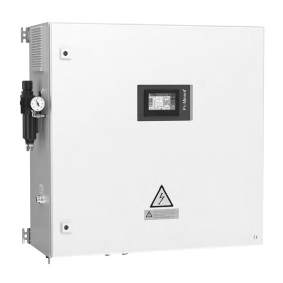
- Page 1 Operating instructions Ozone generation system OZONFILT type OZVb 1 - 4 A ® Please carefully read these operating instructions before use. · Do not discard. The operator shall be liable for any damage caused by installation or operating errors. The latest version of the operating instructions are available on our homepage. Part no.
- Page 2 Supplemental directives Supplementary information Read the following supplementary information in its entirety! Should you already know this information, you will benefit more from referring to the operating instructions. The following are highlighted separately in the document: Enumerated lists Operating guidelines Keys: [UP] key ‘Software interface text’...
-
Page 3: Table Of Contents
Table of contents Table of contents About the product..............6 Identity code................7 Safety..................9 3.1 Labelling of safety information........9 3.2 Warning symbols denoting different types of danger..9 3.3 Intended use..............9 3.4 Personnel qualification..........10 3.5 General Safety Requirements........11 3.6 Safety equipment............ - Page 4 Table of contents 7.4 Assembly..............33 7.4.1 Raw water pipes............33 7.4.2 Ozone gas system........... 34 7.4.3 Cooling water system..........34 7.4.4 Air conditioning system (air conditioning unit, optional)..............34 Electrical installation............36 8.1 Information relating to electrical connections....36 8.2 Electrical inputs and outputs of the system....
- Page 5 Table of contents 11.3 Regular maintenance..........64 Troubleshooting..............66 12.1 Explanation of troubleshooting measures....66 12.2 List of messages............67 Technical data..............74 13.1 Complete system............74 13.2 Electrical inputs and outputs of the OZVb....76 13.3 Supplementary information for modified designs..77 Accessories.................
-
Page 6: About The Product
Additional booster pumps and injectors can therefore be dispensed with in many applications. The integral data logger (optional) writes data to an SD card where it is stored. A ProMinent application is used to visualise the meas‐ ured values on a PC. -
Page 7: Identity Code
20 g/h 35 g/h 70 g/h Operating gas Operating gas - air Design ProMinent with yellow / red master switch ProMinent with grey / black maintenance switch Special version Cooling none Control cabinet air conditioning Control of cooling water heat exchanger... - Page 8 Identity code Ozone generation systems type OZONFILT ® PROFIBUS ® DP interface PROFINET ® interface Additional options None Dewpoint sensor External backflow preventer Back pressure valve Dewpoint sensor + external backflow preventer Dewpoint sensor + back pressure valve External backflow preventer + back pressure valve Dewpoint sensor + external water trap + back pressure valve Mixing equipment (OZVb1-3)
-
Page 9: Safety
All other uses or a modification of the system are only per‐ mitted with the written authorisation of ProMinent GmbH, Hei‐ delberg. The system may not be operated in conditions other than those described in this document. -
Page 10: Personnel Qualification
Service technician The Service department refers to service technicians, who have received proven training and have been authorised by ProMinent ® to work on the system. -
Page 11: General Safety Requirements
Safety 3.5 General Safety Requirements To ensure maximum safety, all persons, who are involved in working with the ozone generation system, must be familiar with the safety regulations and operation of the ozone genera‐ tion system. The ozone generation system must be used in compliance with all relevant regulations. - Page 12 Safety For Germany In addition to the operating instructions, make available the German regulations issued by the Federation of Commercial Pro‐ fessional Associations (HVGB) and the Professional Association of the Chemical Industry (BG Chemie) by way of information, including: DGUV Regulation 103-015 “Guidelines on the use of ozone in water treatment"...
-
Page 13: Components Of The System And Their Function
Components of the system and their function Components of the system and their function 4.1 Overview of OZONFILT ® OZVb 1-4 A 20,21 24 40 25 10 42 P_OF_0086_SW Fig. 1: Ozone generation system OZONFILT ® OZVb 4 A - without air conditioning and without door... - Page 14 Components of the system and their function Component Function Pressure regulating valve with man‐ Unit for adjusting and displaying the priming pressure of ometer the system Ozone generator A portion of the oxygen in the operating gas is converted into ozone in the water-cooled ozone generator. Adjustable operating gas throttle The flow of operating gas for ozone generation can be valve...
- Page 15 Components of the system and their function Component Function Throttle valve for regeneration air The throttle valve is used to adjust the gas flow for regeneration. Drying unit non-return valves The non-return valves prevent the backflow of operating gas into the regeneration gas duct. Drying unit solenoid valve block Cooling water inlet solenoid valve The solenoid valve on the cooling water inlet stops the...
- Page 16 Components of the system and their function P_OF_0081_SW Fig. 2: Ozone generation system OZONFILT OZVb 1 with options ® Pressure regulating valve with manometer 33 Point of injection non-return valve Ozone outlet 63 Backflow preventer (optional) 62 Back pressure valve (accessory) 31 Static helical mixer (optional) 35 Raw water 30 Water mixed with ozone...
- Page 17 Components of the system and their function P_OF_0079_SW Fig. 3: Diagrammatical pneumatic and hydraulic flow in the ozone generation systems OZVb 1-4 A with drying unit for use with air as the operating gas only with OZVb 4 Pressure regulating valve with manometer Ozone generator Adjustable operating gas throttle valve Ozone outlet diaphragm valve...
-
Page 18: Description Of The Ozone Generation System Ozonfilt ® Ozvb
Components of the system and their function 59 Dewpoint sensor (optional) 60 Air outlet dewpoint sensor 61 Air inlet solenoid valve 62 Back pressure valve (optional) 63 Backflow preventer with liquid level sensor (optional) 64 Ball valve 4.2 Description of the ozone generation system OZONFILT ®... -
Page 19: The Ozone Generator
Components of the system and their function A partial flow of the dried air is expanded in the counterflow to atmospheric pressure and discarded to regenerate the drying agent located in the other storage tank. This process removes the moisture adsorbed in the previous cycle from the drying agent and prepares it for the next drying phase. -
Page 20: Backflow Preventer (Optional)
Components of the system and their function 4.2.5 Backflow preventer (optional) The backflow preventer (63) consists of a non-return valve and a water trap with level monitoring. Water flowing back from the point of injection is collected in the water trap and detected by the elec‐ tronic level switch. -
Page 21: Safety Equipment
Components of the system and their function measures and monitors the frequency during high voltage gen‐ eration, monitors the system’s priming pressure, measures and monitors the pressure in the ozone generator (2), measures and monitors the gas flow through the ozone gener‐ ator (2), measures and monitors operating hours, the number of faults and the number of mains power failures in the system,... -
Page 22: Door Safety Switch
Components of the system and their function 4.3.2 Door safety switch The OZONFILT ® OZVb is provided with a door safety switch (13) to ensure that no live parts can be touched. DANGER! Potentially fatal high voltage If the door safety switch (13) is bypassed, parts of the system can become live with potentially fatal high voltage. - Page 23 Components of the system and their function Install the gas detector at positions where the highest concentra‐ tions of ozone are likely in the event of a fault/malfunction. Fit the gas detector close to the ozone generation system. Set the alarm threshold of the gas detector to an ozone concentra‐ tion of 0.5 ppm.
-
Page 24: Ozvb
Operation of the OZONFILT ® OZVb Operation of the OZONFILT OZVb ® The operation of the system can be understood with the aid of the Ä Chapter 4 ‘Components of the general layout drawings in system and their function’ on page 13 and the following description with block diagrams. -
Page 25: Cooling Water Flow
Operation of the OZONFILT ® OZVb P_OF_0079_SW Fig. 4: Hydraulic circuit diagram OZVb 5.3 Cooling water flow The cooling water passes from the cooling water inlet to the angle valve (24), at which the cooling water flow rate can be regulated. From there the cooling water enters the ozone generator (2). -
Page 26: Schematic Diagram Of Water Treatment Using The Ozonfilt ® Ozvb 1-4 A
Operation of the OZONFILT ® OZVb 5.5 Schematic diagram of water treatment using the OZONFILT ® OZVb 1-4 a Control DISPLAY High voltage Temperature Gas detector generation monitoring Compressed air supply Pressure Drying unit Ozone generator monitoring Gas flow rate measurement Temperature measurement... -
Page 27: Scope Of Delivery, Storage And Transport
Scope of delivery, storage and transport Scope of delivery, storage and transport 6.1 Scope of delivery OZVb The system is sub-divided into units: Minimum scope of delivery ozone generation system in the control cabinet operating instructions wiring diagram inspection sheet fixing materials additional options as per the identity control of cooling water heat exchanger... -
Page 28: Transport
Scope of delivery, storage and transport temperature: 5 °C ... 50 °C, max. relative air humidity: 95% - non-condensing, in a non-aggressive environment (no harmful vapours, chemi‐ cals etc.), protected from direct sunlight, rain and moisture, stored vertically. 6.3 Transport WARNING! Incorrect transportation of the system using non- seaworthy wooden crates or horizontal wooden... -
Page 29: Assembly And Installation
Assembly and installation Assembly and installation 7.1 Safety guidelines and general requirements WARNING! Fatal injury by electrocution. The system produces high voltage. – For safety reasons, only allow appropriately qualified technical personnel to install, operate and service this system. – Ensure that all technical personnel are trained by the manufacturer about the specific system. - Page 30 Assembly and installation The room in which the system is installed must be monitored by an ozone warning device, which switches off the plant in the event of a leakage of ozone. The gas detector must provide a visual and acoustic warning. The ozone sensor should be installed where the highest concentration of ozone is to be expected in the event of an accident.
-
Page 31: Requirements Relating To System Components
OZVb 1-4 to the feed point into the raw water (at the point of injection). ProMinent uses stainless steel or PVC mixing modules, with inte‐ gral non-return valve made of high-alloy stainless steels. The non-return valve prevents damage to the OZONFILT ®... -
Page 32: Ozone Removal From Filters And Reaction Section
Assembly and installation CAUTION! It is imperative that a non-return valve is fitted directly at the point of injection for the correct and proper operation of the ozone generation system. The pressure drop through the valve with a nom‐ inal gas flow rate must be low and the valve may only be manufactured from ozone-resistant mate‐... -
Page 33: Assembly
Assembly and installation WARNING! This means that destruction systems for gaseous ozone, in which active carbon is used, are not suit‐ able for OZONFILT®OZVb systems. During ozone destruction by active carbon destruc‐ tors, there is a risk of explosion, specifically with systems, which generate high concentrations of ozone gas, if the ozone accumulates in the active carbon layer. -
Page 34: Ozone Gas System
Assembly and installation 7.4.2 Ozone gas system WARNING! – The pipework connecting the ozone outlet of the OZONFILT OZVb 1-4 to the point of injec‐ ® tion in the mixing equipment should be made of stainless steel or PTFE hose. –... - Page 35 Assembly and installation WARNING! Disconnect the mains voltage prior to opening the unit. Discharge the condensate produced during the cooling process in the usual way - refer to the operating instructions for the air condi‐ tioning unit.
-
Page 36: Electrical Installation
Electrical installation Electrical installation 8.1 Information relating to electrical connections CAUTION! Warning of incorrect operation and defects – The mains cable enters at the bottom right; all other electric cables (signal leads) enter through the top of the control cabinet. All the electrical supply cables to the plant must pass through the strain relief screw connections into the inside of the system. - Page 37 Electrical installation "Pause" contact input This input can be used to place the system in PAUSE status. The input is isolated from all other electrical components of the system. "Contact open" indicates that PAUSE status is enabled. "Process water flow" contact input This input can be used to place the system in PAUSE status by means of the minimum contact of a process water flow meter.
-
Page 38: Commissioning
– Persons are deemed to be qualified as tech‐ nical personnel, if they have undergone a training course from ProMinent and have the requisite authority. All warranty and liability claims on the part of the system operator will not be admitted following interference by unauthorised personnel. - Page 39 Commissioning all system parameters are within the permissible range - see "Technical data", "Assembly and installation" and "Safety” chapters, all safety equipment is fitted and working correctly, all safety signs have been fixed in place, the supply of compressed air or oxygen complies with the regu‐ lations.
- Page 40 Commissioning Ä Chapter 9.2 ‘Adjusting Set the desired process gas flow - the process gas flow’ on page 41 . CAUTION! The pressure sensor (6) in the control cab‐ inet measures the operating pressure. The measured value is displayed on the touch panel with “...
-
Page 41: Adjusting The Gas Priming Pressure
9.2 Adjusting the process gas flow WARNING! Hazardous residual voltage The following adjustments need to be made by a ProMinent-trained expert when the system is run‐ ning with the cabinet door open. – Wait at least 5 minutes after the supply of... -
Page 42: Adjusting The Cooling Water Flow
9.3 Adjusting the cooling water flow WARNING! Hazardous residual voltage The following adjustments need to be made by a ProMinent-trained expert when the system is run‐ ning with the cabinet door open. – Wait at least 5 minutes after the supply of... -
Page 43: Setting The Control Variable
Commissioning 9.4 Setting the control variable CAUTION! It is essential that you ensure that the ozone gen‐ erator is fully filled with cooling water before setting an ozone control variable above 3%. You will rec‐ ognise this by the constant display of the cooling water flow rate on the touch panel. - Page 44 Commissioning Example A maximum of 4 g/h of ozone is needed in a process. The OZVb 1 A is available with its performance data: Tab. 3: Performance data of the OZVb 1 A Nominal ozone output at 100%: 10 g/h Nominal gas flow rate: 500 Nl/h N [%]...
- Page 45 Commissioning CAUTION! Unexpected shut-downs with gas flow rate of less than 30% If you establish a value of less than 30% when determining the gas flow, there is a danger that the system is being operated at too close to your lower gas flow rate limit and therefore constantly shuts down in operation.
-
Page 46: Operation
Operation Operation Switch the system on by turning the master switch to "1". 10.1 Displays, structure Continuous display The system “wakes up” in the continuous display: OZVb 08:05:53 1.27 bar (over) 504 l/h EXPERT 100% 19 l/h 16.5 °C 9.60 g/h B1048 Fig. - Page 47 Operation OZVb Measured data 08:05:53 Logout Pneu- Electrical matic data data B1060 Fig. 8: Other parts of the touch panel - here showing the ‘Measured data’ menu [HOME] key Designation of the system Name of the menu [LOGOUT] key Sub-menus Lost in hyperspace Press [HOME] if you wish to switch from any...
-
Page 48: Authorisation Scheme
Operation Abbre Full text Effect via‐ tion Backspace deletes last digit Clear screen clears the entire input Enter Input A large screen keyboard appears if letters also need to be entered. Tab. 4: Alarm Colour codes Colour codes Meaning blue no errors yellow / blue, flashing Warning... - Page 49 Operation B1062 The authorisation concept has various access levels: Level User name EXPERT SERVICE CAUTION! ‘Change Password’ lets you enter your own pass‐ words. Forgotten passwords can only be reset by a COM‐ PLETE reinitialisation of the HMI. – If you are using your own passwords, be sure to record them and make them easy to find.
-
Page 50: Operating Menu, Structure
Operation 10.3 Operating menu, structure OZVb 1.27 bar (over) 08:05:53 504 l/h Measured data 100% 19 l/h Status 16.5 °C Information Operation System 9.60 g/h OZVb Measured data Measured data 08:05:53 Pneu- Electrical matic data data OZVb Status Status 08:05:53 Statistics OZVb Information... -
Page 51: Menus, Description
Operation 10.4 Menus, description 10.4.1 Measured data OZVb Measured data 08:05:53 Pneu- Electrical matic data data B1050 Fig. 10 ‘Measured data è ...’ 10.4.1.1 Pneumatic data ‘Measured data è Pneumatic data è ...’ Pneumatic operating data can be read off here. 10.4.1.2 Electrical data ‘Measured data è... -
Page 52: Information
Operation 10.4.2.1 Statistics ‘Status è Statistics è ...’ Different statistical data can be read off here. These parameters can be changed: ‘Maintenance interval’ ‘Maintenance warning’ Tap in the corresponding field. ð A screen keyboard appears. [Ent] . Enter the required value and press You can also reset: ‘Number of Start/Stop’... -
Page 53: Operation
Operation IP address Subnet mask Software version, PLC Programmable Logic Controller Software version, HMI 10.4.3.2 Alarms ‘Information è Alarms è ...’ The actual message consists of: the number of the message (e.g. “093”) the identifier: A = alarm, W = warning plain text (e.g. - Page 54 Operation Authorised people can enter in the ‘Control variable’ field from where the system is to obtain its control variable: ‘Internal’ : Manual specification of the control variable on the touch panel ‘External’ : Specification of the control variable via a standard signal inter‐ face 0/4-20mA.
-
Page 55: System
Operation Authorised persons can enter different times in this menu. 10.4.4.3 Counter ‘Operation è Counter è ...’ Authorised persons can enter different parameters in this menu. 10.4.5 System OZVb System 08:05:53 Date Calibration Display Time Fault Files handling B1067 Fig. 14 ‘System è... -
Page 56: Functional Process
Operation Authorised persons can set the date and time in this menu. 10.4.5.3 Display ‘System è Display è ...’ Authorised persons can set different parameters for the LCD dis‐ play in this menu. 10.4.5.4 Languages (flags) ‘System è Languages è ...’ Authorised persons can set the operating language in this menu. -
Page 57: Important System Statuses
Operation ‘PAUSE’ mode has not been activated externally, the system has not been enabled by the existence of additional locking contacts (process water flow rate, gas detector) and there are no other faults. When the system is started up for the first time, the required ozone volume ( ‘Control variable’... -
Page 58: Process Water Flow Too Low" Operating Status
Operation on the touch panel, a corresponding error message appears in plain text - see , the operating signal relay and the fault signal relay are acti‐ vated. 10.6.4 "Process water flow too low" operating status Should the system be locked by an external flow detector for process water and the flow rate of the process water is interrupted or falls below the minimum flow rate set on the meter, the control ‘Stop’... -
Page 59: Displays
Operation 10.7 Displays 10.7.1 Complete system The following functions and displays can be seen in normal mode: the master switch is set to ON, the fuse protection inside the system has not been triggered, the system priming pressure is within the permissible range, the pressure at the point of injection is within the permissible range, no faults are displayed on the touch panel. -
Page 60: Ozone Generator Pressure
Operation 10.8.5 Ozone generator pressure The gas pressure for ozone generation is monitored by the pres‐ sure sensor (6) and displayed on the touch panel. The pressure relief valve (8) limits the pressure to non-critical values. The actual gas pressure in the ozone generator depends on the pressure of the process water at the point of injection, the back pressure of the pneumatic equipment (5, 43) between the ozone inlet and the point of injection, and the flow rate of the gas. - Page 61 Operation Tab. 8 Colour code System status Effect green system stopped starts system system running stops system The table also shows the effect that pressing the key has with each colour.
-
Page 62: Maintenance
11.1 Safety guidelines for maintenance and repair Only allow qualified personnel and personnel authorised by ProMinent to perform maintenance and repair work on the system. Ensure that persons who undertake maintenance and repair work on the system have read and understood the operating instructions and in particular the "Safety”... -
Page 63: Routine Inspection
Maintenance 11.2 Routine inspection The following table outlines recommended routine inspections, which OZONFILT ® OZVb systems should undergo. Keep a written record of all maintenance and inspection work undertaken. A tem‐ plate for this record can be found in the Appendix. Keep a logbook for the system. -
Page 64: Regular Maintenance
Maintenance 11.3 Regular maintenance WARNING! Observe the safety guidelines for maintenance - Ä Chapter 11.1 ‘Safety guidelines for maintenance and repair’ on page 62 . CAUTION! Service the OZONFILT ® OZVb 1- 6 at least 1x per year to maintain the correct and proper operation and safety of the system. - Page 65 – Immediately stop the system and shut it down. – Call Service or expert personnel authorised by ProMinent. CAUTION! Refer to the operating instructions for the filter unit. The filter unit is on the outside of the OZONFILT ®...
-
Page 66: Troubleshooting
Troubleshooting Troubleshooting 12.1 Explanation of troubleshooting measures WARNING! – Disconnect the system from the supply voltage before starting work on the OZONFILT ® OZVb for troubleshooting or to remedy faults. – Ensure that the system cannot accidentally be reconnected to the mains while work on the system is being carried out. -
Page 67: List Of Messages
Troubleshooting If a ‘switching-off threshold’ is transgressed, the controller displays a fault alert on the touch panel and switches the system off. With digital variables, it switches the system off when the limit value set on the sensor is transgressed. ‘alarm delay’... - Page 68 Troubleshooting Error Error message Switch-off due Cause Remedy to... ‘Guard doors open’ Door switch The contact in the Close the control cabinet door. monitoring door switch has trig‐ mechanism gered ‘Overtemperature of Temperature The temperature of Raise the water temperature at ozone generator’...
- Page 69 Troubleshooting Error Error message Switch-off due Cause Remedy to... ‘Overflow xxxxx’ Pressure sensor, flow sensor, tem‐ perature sensor ‘Gas flow too low’ Gas flow sensor The operating gas Check the system priming pres‐ flow through the sure and increase if necessary. ozone generator is too Check for excessive back pres‐...
- Page 70 Troubleshooting Error Error message Switch-off due Cause Remedy to... see 011 see 012 ‘Cooling water Cooling water Cooling water tem‐ Raise the water temperature at temperature too outlet tempera‐ perature below 3 °C the cooling water inlet. low’ ture sensor ‘Cooling water Cooling water Cooling water tem‐...
- Page 71 Troubleshooting Error Error message Switch-off due Cause Remedy to... ‘Power unit 1/2 043 / Temperature The temperature of Check that the control cabinet fan temperature too measurement some components on is working correctly. high’ at the power the power unit is too Clean the fan filter.
- Page 72 Troubleshooting Error Error message Switch-off due Cause Remedy to... Only with 2 ozone The measuring range Lower the cooling water flow at generators: Cooling of the flow meter for the angle valve (24) so that reli‐ water flow 2 too the cooling water has able values can be displayed high...
- Page 73 Troubleshooting Error Error message Switch-off due Cause Remedy to... Water trap full!! Water trap Water penetrates from Do not start up the system with (optional) the point of injection ozone! There is a threat of major into the gas system. material damage! Check whether there is water in the system’s gas system, dry the...
-
Page 74: Technical Data
Technical data Technical data WARNING! Risk of personal injuries Please observe the ”Supplement for modified ver‐ sion“ at the end of the chapter! It replaces and supplements the technical data! 13.1 Complete system Ambient parameters Parameter Value Max. temperature: 40 °C Max. - Page 75 Technical data Ozone generation sys‐ Unit OZVb 1 A OZVb 2 A OZVb 3 A OZVb 4 A tems without air conditioning IP 54 IP 54 IP 54 IP 54 with air conditioning to the inside: IP to the inside: IP to the inside: IP to the inside: IP to the outside:...
-
Page 76: Electrical Inputs And Outputs Of The Ozvb
Technical data N [%] p [bar P_OF_0089_SW ü Fig. 15: Ozone output diagram Ozone output in % Pressure in bar over ΔW Working range 13.2 Electrical inputs and outputs of the OZVb A wiring diagram is also enclosed with the docu‐ mentation for the system. -
Page 77: Supplementary Information For Modified Designs
Technical data * +/- 2 V Contact open Data Value Unit Resistance R > 50 ㏀ Contact closed Data Value Unit Resistance R < 1 ㏀ Standard signal output (mA): Standard signal input 1 (control variable) Data Value Unit Current range** 0/4 ... -
Page 78: Accessories
Accessories Accessories 14.1 Classification Compulsory accessories: Ozone detector Recommended accessories (available on request): Mixing unit with non-return valve Residual ozone destruction unit Reaction chamber with air vent 14.2 Description Gas detector for ozone The gas detector type “Neon ® GAS” is designed as a compact measuring and switching unit for monitoring the ambient air for dangerous concentrations of ozone. - Page 79 Accessories Flow Length Connector Order no. m³/h 50 – 90 1,300 DN125 1034641 90 – 160 1,700 DN150 1034640 Tab. 10: Material 1.4404 Flow Length Connector Order no. m³/h 5 – 10 DN40 1022503 10 – 15 DN50 1022514 15 – 25 DN65 1022515 25 –...
- Page 80 Accessories PVC version Active carbon granulate-based residual ozone destructor in a PVC housing. Tab. 11 Type Ozone volume * Order no. (g/h) Residual ozone destructor 3 879022 Residual ozone destructor 1004267 14 l Residual ozone destructor 879019 30 l * The stated ozone quantities refer to quantities added to the raw water.
- Page 81 Accessories * Types 18 to 110 m /h additionally with ball valve Rp 1/2" as a condensation drain CAUTION! The residual ozone gas destructor should only be used in chlorine-free gas flows. The PVC version should therefore be used with swimming pool applications.
-
Page 82: Dimensional Drawings
Dimensional drawings Dimensional drawings 210 60 DN Ld [mm] 88,9 x 270 P_OF_0082_SW Fig. 16: Dimensional drawing of the OZVb system 1+2 A; dimensions in mm, drawing is not strictly binding Pos. Connector Ozone outlet G 3/8” f Cooling water outlet G 1/4” f Cooling water inlet G 1/4”... - Page 83 Dimensional drawings DN Ld [mm] 88,9 x 270 P_OF_0083_SW Fig. 17: Dimensional drawing of the OZVb system 3 A; dimensions in mm, drawing is not strictly binding Pos. Connector Ozone outlet G 3/8” f Cooling water outlet G 1/4” f Cooling water inlet G 1/4”...
- Page 84 Dimensional drawings (DN 25, 40, 50, 65) 88,9 x 270 G3/8i P_OF_0084_SW Fig. 18: Dimensional drawing of the OZVb system 4 A; dimensions in mm, drawing is not strictly binding Pos. Connector Ozone outlet G 3/8” f Cooling water outlet G 1/4” f Cooling water inlet G 1/4”...
-
Page 85: Operating Report
Operating report Operating report Fig. 19... -
Page 86: Operating Menu, Structure
Operating menu, structure Operating menu, structure OZVb 1.27 bar (over) 08:05:53 504 l/h Measured data 100% 19 l/h Status 16.5 °C Information Operation System 9.60 g/h OZVb Measured data Measured data 08:05:53 Pneu- Electrical matic data data OZVb Status Status 08:05:53 Statistics OZVb... -
Page 87: Ozvb Operating Menu, Overall
OZVb operating menu, overall OZVb operating menu, overall 1st level Measured data Pneumatic data Control variable Ozone quantity Gas flow rate Pressure O3 generator Cooling water Electrical data Control variable Ozone quantity Mains voltage Mains current Primary voltage Primary current Active power DC voltage DSP temperature... - Page 88 OZVb operating menu, overall 1st level System Identity code Project number Serial number Software version, PLC Programmable Logic Controller Inspection date Operation Operating mode Control variable internal external Sensor type Control range Valves Automatic / Manual Times Cycle time Changeover cycle Purge cycle Pressure build-up time Idle time...
- Page 89 OZVb operating menu, overall 1st level Setpoint ozone gener‐ Analogue input ator Actual value Sensor type Measuring range Ramp up Ramp down Ozone output Control variable internal Ozone concentra‐ tion Gas flow rate Ozone quantity Setpoint ozone gener‐ Analogue input ator Actual value Sensor type...
- Page 90 OZVb operating menu, overall 1st level Electrical settings Mains voltage Warning level Mains current Alarm level Primary voltage Switch-on delay Primary current Switch-off delay Active power Files Log files Production data Commissioning data Persistent data Pressure correction data Linearisation files Event texts Data...
-
Page 91: Declaration Of Conformity
Declaration of Conformity Declaration of Conformity ProMinent GmbH Im Schuhmachergewann 5 - 11 D - 69123 Heidelberg, Germany, hereby declare that the product specified in the following, complies with the relevant basic health and safety requirements of the Direc‐ tive, on the basis of its functional concept and design and in the version distributed by us. -
Page 92: Information On The Legally Compliant Use Of Ozone
Below a production volume of 1 t/year (= 114 g/h continuous output), no registration is required. For further information, please contact EurO zon at: www.euro3zon.org/LoA/IndexReach . ProMinent GmbH, member of EurO zon ivzw... -
Page 93: Index
Index Index Commissioning ......38 Commissioning data ..... . 56 About the product . - Page 94 Index Enter control variable ..... 54 Lost in hyperspace ..... . . 47 Entering values .
- Page 95 Index Ozone pressure ......56 Ozone quantity ......59 Safety chapter .
- Page 96 Index Treiber ....... . 56 Troubleshooting ......66 Unit switchover .
- Page 100 ProMinent GmbH Im Schuhmachergewann 5-11 69123 Heidelberg Germany Telephone: +49 6221 842-0 Fax: +49 6221 842-419 Email: info@prominent.com Internet: www.prominent.com 982470, 5, en_GB © 2018...
Need help?
Do you have a question about the OZONFILT OZVb 1 A and is the answer not in the manual?
Questions and answers