Table of Contents
Advertisement
Quick Links
Advertisement
Table of Contents

Subscribe to Our Youtube Channel
Related Manuals for Buchi Sepiatec SFC-50


Summary of Contents for Buchi Sepiatec SFC-50
- Page 1 Sepiatec SFC-50 Operation Manual...
- Page 2 CH-9230 Flawil 1 E-Mail: quality@buchi.com BUCHI reserves the right to make changes to the manual as deemed necessary in the light of experience, especially with respect to structure, illustrations and technical details. This manual is copyrighted. Information from it may neither be reproduced, distributed, or used for competitive purposes, nor made available to third parties.
-
Page 3: Table Of Contents
Electric and electronic connections ................ 16 3.2.3 CO₂- and coolant connections ................ 17 3.2.4 Exhaust connections .................... 17 Scope of delivery ......................... 18 Technical data ........................ 18 3.4.1 Sepiatec SFC-50 .................... 18 3.4.2 Ambient conditions .................... 19 3.4.3 Solvents........................ 19 3.4.4 Detectors ........................ 19 3.4.5 Pumps ........................ - Page 4 Operation.......................... 51 System start - up ......................... 51 Positioning of the sample .................... 51 Positioning the fractionation bottles.................. 52 Method selection ......................... 52 Starting a run ........................ 53 Finishing a run ........................ 53 Shutting down the system .................... 54 Using the emergency switch.................... 54 Operation Manual Sepiatec SFC-50...
- Page 5 Assembling ...................... 57 Gas-liquid-separators (GLS).................... 58 Help with faults ........................ 60 Troubleshooting........................ 60 Taking out of service and disposal.................. 61 10.1 Taking out of service ...................... 61 10.2 Disposal.......................... 61 10.3 Returning the instrument ..................... 61 Appendix .......................... 62 11.1 Spare parts and accessories .................... 62 Operation Manual Sepiatec SFC-50...
-
Page 6: About This Document
Connected instruments In addition to this operation manual, follow the instructions and specifications in the documentation for the connected instruments. 6/64 Operation Manual Sepiatec SFC-50... -
Page 7: Safety
— Safety-related incidents that occur while using the instrument should be reported to the manufacturer (quality@buchi.com). BUCHI service technicians Service technicians authorized by BUCHI have attended special training courses and are authorized by BÜCHI Labortechnik AG to carry out special servicing and repair measures. -
Page 8: Personal Protective Equipment
The instrument has been developed and manufactured using the latest technological advances. Nevertheless, risks to persons, property or the environment can arise if the instrument is used incorrectly. Appropriate warnings in this manual serve to alert the user to these residual dangers. 8/64 Operation Manual Sepiatec SFC-50... -
Page 9: Faults During Operation
Do not continue to use glass components that are damaged. Always wear protective gloves when disposing of broken glass. 2.7.6 Malfunction of a connected instrument (option) A malfunction on a connected instrument can cause poisoning or death. Operation Manual Sepiatec SFC-50 9/64... -
Page 10: Malware Infection Due To Connections With Other Devices Or Network
Unauthorized modifications can affect safety and lead to accidents. Use only genuine BUCHI accessories, spare parts and consumables. Carry out technical changes only with prior written approval from BUCHI. Only allow changes to be made by BUCHI service technicians. BUCHI accepts no liability for damage, faults and malfunctions resulting from unauthorized modifications. - Page 11 300 bar. NOTE The system my be pressurized after switching off. Keep in mind, the escape of pressurized gases and solvents are possible. Operation Manual Sepiatec SFC-50 11/64...
-
Page 12: Product Description
With the optional solvent selection valve, the solvent can be chosen from four different solvents. — Injection of liquid or solid sample — Separation on a column — Detection of the components by using a UV, ELSD or MS detector. — Collecting the desired fractions 12/64 Operation Manual Sepiatec SFC-50... - Page 13 The Detection and Fraction valve position decides in which GLS the stream is going. The GLS separates most of the CO and removes it from the system by an exhaust pipe and fed into the ventilation system. Operation Manual Sepiatec SFC-50 13/64...
-
Page 14: Configuration
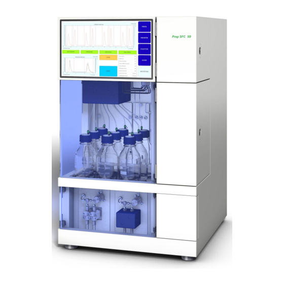
The fractions are available in highly concentrated form for further analysis. Configuration 3.2.1 Front view Touchscreen Gas-liquid-separator and modifier pump Detector flap Fraction collector valve Column oven Syringe Add-on pump (optional) 14/64 Operation Manual Sepiatec SFC-50... - Page 15 Büchi Labortechnik AG Product description | 3 Column oven Column holder Flow cell with optic fibre cable Injection valve Column selector valve Leak sensor Heating module Filter Check valves Operation Manual Sepiatec SFC-50 15/64...
-
Page 16: Electric And Electronic Connections
Büchi Labortechnik AG 3 | Product description 3.2.2 Electric and electronic connections Fuses and FI-circuit breaker USB connection HDMI connection Main switch LAN external connection LAN internal connection Emergency switch connection Fraction compartment exhaust 16/64 Operation Manual Sepiatec SFC-50... -
Page 17: Co₂- And Coolant Connections
— On the left side is the exhaust of the fractionation compartment. — On the right side is the outlet of the CO safety exhaust valve. — On the rear side is the GLS CO exhaust. Operation Manual Sepiatec SFC-50 17/64... -
Page 18: Scope Of Delivery
Electrically operated 11-port / 10-ways valve Tubing Stainless steel capillary tubes OD: 1/16´´ ID: 1.0 mm or 0.5 mm or 0.25 Pump head temperature control Chiller Method development On analytical columns (ID: 4 − 4.6 mm) 18/64 Operation Manual Sepiatec SFC-50... -
Page 19: Ambient Conditions
UV wavelengths range 190 − 500 nm UV wavelengths selectable Standard ELSD Optional Optional 3.4.5 Pumps Pump 30 ml/min Flow rate Pump Max. 400 bar Pressure Modifier pump 1 pcs. Modifier pump 30 ml/min Flow rate Operation Manual Sepiatec SFC-50 19/64... - Page 20 Büchi Labortechnik AG 3 | Product description Modifier pump Max. 400 bar Pressure Add-on pump Optional Flow rate accuracy ±1% or ±0.3 ml/min Precision 0.25% from 1 ml/min to 20 ml/min at 20 °C 20/64 Operation Manual Sepiatec SFC-50...
-
Page 21: Transport And Storage
The instrument should be transported by two persons at the same time. Lift the instrument at the points indicated. Lift the instrument – this requires two persons each lifting at one of the points indicated on the bottom of the instrument. Operation Manual Sepiatec SFC-50 21/64... -
Page 22: Installation
Make sure that the power supply can be disconnected at any time in an emergency. A BUCHI service engineer or an authorized representative will unpack and check the consignment carefully to ensure that all modules and accessories are in proper condition. -
Page 23: Before Installation
CO supply in the event of danger. Before installation NOTICE Instrument damage due to switching it on too early. Switching on the instrument too early after transportation can cause damage. Climatize the instrument after transportation. Operation Manual Sepiatec SFC-50 23/64... -
Page 24: Establishing Electrical Connections
Risk of instrument damage because of not suitable power supply cables. Not suitable power supply cables can cause bad performance or an instrument damage Use only BUCHI power supply cables. Precondition: R The electrical installation is as specified on the type plate. -
Page 25: Software
ð The system checks if all the functional elements are responding properly. 6.1.2 Entering values Enter numbers Tap on an entry field. ð The display shows a dialog box with a numeric input box. Enter the value. Operation Manual Sepiatec SFC-50 25/64... -
Page 26: Exiting The Software
Exiting the software Precondition: R Run is finished. R Pumps are switched off. Tap the [EXIT] button to exit the software. ð Prep SFC control software closes. Layout Name Description To display the measured values. display Chromatogram 26/64 Operation Manual Sepiatec SFC-50... -
Page 27: Manual Tab
[SERVICE] button To open the service settings of the system. [Windows] button To exit the control software. Opens the win- dows home screen. MANUAL tab Name Description To start and stop a run manually. MANUAL Operation Manual Sepiatec SFC-50 27/64... -
Page 28: Rinsing The Tubing And Syringe
ð The display shows a dialog box with a numeric input box. Enter the value. Tap the [OK] button to confirm. ð The value is saved. ð The dialog box closes. 28/64 Operation Manual Sepiatec SFC-50... -
Page 29: Starting The Pump
NOTICE! An automatic run can be started, while the pump is still running but the injection has to be finished. The chromatogram can then be called up in the menu. The frac- COLLECTION tionation parameters can be adjusted for automated further separations. Operation Manual Sepiatec SFC-50 29/64... -
Page 30: Setting Detector Signal To Zero
Tap the [BACK TO MAIN VIEW] button to close the service view window. ð The window closes automatically. PARAMETER tab The parameter menu has two isocratic modes depending on the configuration: — UV detector — DAD detector (optional) 30/64 Operation Manual Sepiatec SFC-50... -
Page 31: Setting New Methods
Modifier Selection of pump inlet at the modifier pump. 6.4.1 Setting new methods Navigation path: PARAMETER ➔ Tap the [METHOD NAME] button. ð The display shows a dialog with an alphanumeric input box. Operation Manual Sepiatec SFC-50 31/64... -
Page 32: Setting Gradient Mode
Tap on the field on the control panel with a blue or white background to enter time, modifier and flow values. Enter the value. Tap the [OK] button to confirm. ð The value is saved. ð The dialog box closes. 32/64 Operation Manual Sepiatec SFC-50... -
Page 33: Loading Saved Methods
NOTICE! The number of injections to be carried out in sequence is not saved in the method and must be specified again whenever reloading the method or starting the system. 6.4.3 Loading saved methods Navigation path: PARAMETER ➔ Operation Manual Sepiatec SFC-50 33/64... -
Page 34: Editing Saved Methods
[T/P] button Switches on the combined fractionation. In this mode, the peaks are searched inside the programmed intervals. Peak No. Number of peaks to be collected. Vial Fractionation bottle in which the fraction is collected. 34/64 Operation Manual Sepiatec SFC-50... - Page 35 Intermediate part between the peaks, the Valley. NOTE Up to eight fractions in total can be collected. All parts of a run that are not to be collected will be captured in the waste container. Operation Manual Sepiatec SFC-50 35/64...
- Page 36 If the peak is smaller, the run is automatically stopped. The minimum height is in percentage. If the peak is smaller, the run is automatically stopped. 36/64 Operation Manual Sepiatec SFC-50...
- Page 37 Chromatogram of the first injection. Multiple injections Chromatogram of multiple injections. Stack injections Chromatogram of stack injection. Stack time The time between one injection and the next. Start second injection Time when the second injection takes place. Operation Manual Sepiatec SFC-50 37/64...
-
Page 38: Setting Peak Control
Tap the [OK] button to confirm. 6.5.2 Setting stack injection The stack injection in isocratic mode allows time saving fractionation of large samples. The sample portions are injected after the elution of a peak. Navigation path: COLLECTION ➔ 38/64 Operation Manual Sepiatec SFC-50... -
Page 39: System Tab
Back Pressure Indicates the back pressure in the system in bar. Thermostat Temperature in the heat exchanger in °C. Preheater Temperature in the preheater in °C. Operation Manual Sepiatec SFC-50 39/64... -
Page 40: Controlling The Back Pressure
The white field shows the status of the CO valve. Navigation path: SYSTEM ➔ Precondition: R Displayed CO VALVE status: Closed. Tap the [OPEN] button. ð The valve opens. CO VALVE status changes to Open. 40/64 Operation Manual Sepiatec SFC-50... -
Page 41: Controlling The Purge Pump
Select the modifier inlet and the flow rate. Tap the [Pump Start] button to start the process. Tap the [Pump Stop] button to close the purge valve at the pump and exit purge. Operation Manual Sepiatec SFC-50 41/64... -
Page 42: Run Method Tab
Peak control is on. The peak being monitored ange) has moved and the collection window was adjusted automatically. [PEAK CONTROL] button Peak control is on. The peak being monitored (red) is outside the collection range and the run was stopped. 42/64 Operation Manual Sepiatec SFC-50... -
Page 43: Before Starting A Run
The button allows changing parameters dur- ing the run. 6.7.1 Before starting a run Navigation path: RUN METHOD ➔ Tap the [Start] button. ð The display shows a dialog with an alphanumeric input box. Enter sample name. Operation Manual Sepiatec SFC-50 43/64... -
Page 44: Changing During A Run
6.8.1 Change No. of Injections Navigation path: ➔ [Change] RUN METHOD ➔ NOTICE! This window close automatically after 10 seconds if no selection is made. 44/64 Operation Manual Sepiatec SFC-50... -
Page 45: Change Injection And Run Time Parameter
RUN METHOD ➔ NOTICE! This window close automatically after 10 seconds if no selection is made. Tap the [Injection] or [Run Time] button to change parameters. ð The display shows a dialog with a numeric input box. Operation Manual Sepiatec SFC-50 45/64... -
Page 46: Change Fraction Parameter
NOTICE! The method for the fractionation (time and/or peak based) as well as the Start peak detect time can not be changed after the run is started. These buttons are just for information. 46/64 Operation Manual Sepiatec SFC-50... -
Page 47: Co₂ Recycling Module
➔ [SERVICE] MANUAL ➔ Name Description To start and stop a run manually. MANUAL [EMERGENCY STOP] button To perform the EMERGENCY STOP. [BACK TO MAIN VIEW] but- To go back to the MANUAL tab view. Operation Manual Sepiatec SFC-50 47/64... - Page 48 [Close all Fraction Valves] This button closes all fractional valves for a button service on the recycling module. Software Version Displays the current software version. 48/64 Operation Manual Sepiatec SFC-50...
- Page 49 This value indicates that fractionation is in progress and how long the fraction valve in is still open. Functional description If the Recycling Inlet Pressure and Recycling Outlet Pressure are approximately equal, the CO pump is supplied with recycled CO Operation Manual Sepiatec SFC-50 49/64...
- Page 50 It will close and open the lower valve (fraction valve out) to transfer the fractionated liquid to the collection container. 50/64 Operation Manual Sepiatec SFC-50...
-
Page 51: Operation
ð Prep SFC control software window opens. Tap the [Verify] button to ensure that all modules are communicating correctly. Positioning of the sample NOTE The capillary tubes should descend in a straight line and without tension. Operation Manual Sepiatec SFC-50 51/64... -
Page 52: Positioning The Fractionation Bottles
Tap the [Load] button to select the method you intend to use. Specify the number of injections which have to take place in sequence. Check if the correct column is in place at the selected column position. Tap the menu button. COLLECTION 52/64 Operation Manual Sepiatec SFC-50... -
Page 53: Starting A Run
ð The injection can be started when the set temperature conditions are reached. Finishing a run NOTE After a run is finished, the pumps stop automatically and the CO stop valve is closed automatically. The temperature controllers and the back pressure regulator will remain active. Operation Manual Sepiatec SFC-50 53/64... -
Page 54: Shutting Down The System
ð This closes the CO stop valve that no more can emerge. ð The windows computer is still running. No data gets lost by the emergency switch off. 54/64 Operation Manual Sepiatec SFC-50... -
Page 55: Cleaning And Servicing
Do not carry out any servicing and cleaning operations that involve opening the housing. Use only genuine BUCHI spare parts in order to ensure correct operation and preserve the warranty. Carry out the service and cleaning operations described in this section to extend the lifetime of the instrument. -
Page 56: Servicing The Injection Valves
For further instructions please consult the manufacturer’s manual for the Knauer Detector UVD 2.1S. Back pressure regulator valve Please contact the BUCHI Customer Service if any problems occur with the back pressure regulator valve. Fractionation valve 8.5.1 Cleaning the valve and replacing the rotor The valve can be cleaned by rinsing through all the channels with a suitable solvent. -
Page 57: Dismantling
Check the surface of the stator. Replace it if there are any scratches between the connections. Contact BUCHI Customer Service to have the part examined to ascertain whether it can be reconditioned. Use suitable solvents to clean all parts and take care to avoid scratching the surfaces. -
Page 58: Gas-Liquid-Separators (Gls)
Test the valve in the system under pressure. Please contact BUCHI Customer Service if problems persist. Gas-liquid-separators (GLS) NOTE To avoid contamination in the collected fractions, it is recommended to flush the gas-liquid separators with a CO₂... - Page 59 Carefully pull the blue insulation vertically downwards from the GLS. Use the GLS key provided to open the GLS by turning it to the left. Hold the GLS with one hand and take it out. Operation Manual Sepiatec SFC-50 59/64...
-
Page 60: Help With Faults
Pressure fluctuation Check valves are dirty or Clean or replace check valves. worn out See pump manual. Set temperatures Defective heating elements Contact BUCHI Customer are not reached Service Defective temperature con- trol 60/64 Operation Manual Sepiatec SFC-50... -
Page 61: Taking Out Of Service And Disposal
When disposing, observe the disposal regulations of the materials used. Materials used see Chapter 3.4 "Technical data", page 18. 10.3 Returning the instrument Before returning the instrument, contact the BÜCHI Labortechnik AG Service Department. https://www.buchi.com/contact Operation Manual Sepiatec SFC-50 61/64... -
Page 62: Appendix
Appendix 11.1 Spare parts and accessories Use only genuine BUCHI consumables and spare parts in order to ensure correct, safe and reliable operation of the system. NOTE Any modifications of spare parts or assemblies are only allowed with the prior written permission of BUCHI. - Page 64 We are represented by more than 100 distribution partners worldwide. Find your local representative at: www.buchi.com...
Need help?
Do you have a question about the Sepiatec SFC-50 and is the answer not in the manual?
Questions and answers