Table of Contents
Advertisement
Quick Links
Advertisement
Table of Contents

Related Manuals for Buchi Inert Loop S-395


Summary of Contents for Buchi Inert Loop S-395
- Page 1 Inert Loop S-395 Operation Manual...
- Page 2 CH-9230 Flawil 1 E-Mail: quality@buchi.com BUCHI reserves the right to make changes to the manual as deemed necessary in the light of experience, especially with respect to structure, illustrations and technical details. This manual is copyrighted. Information from it may neither be reproduced, distributed, or used for competitive purposes, nor made available to third parties.
-
Page 3: Table Of Contents
Before installation ........................ 17 Establishing electrical connections.................. 17 Installing the exhaust gas hose ................... 17 Installing the solvent receiving vessel ................. 18 Installing the oxygen sensor for the first time .............. 19 Installations for a spray drying mode................... 19 Operation Manual Inert Loop S-395... - Page 4 Installing the oxygen sensor ................... 28 Help with faults ........................ 30 Error messages ........................ 30 Taking out of service and disposal.................. 31 Taking out of service ...................... 31 Refrigerant........................... 31 Disposal.......................... 31 Returning the instrument ..................... 31 Appendix .......................... 32 10.1 Spare parts .......................... 32 Operation Manual Inert Loop S-395...
-
Page 5: About This Document
Trademarks Product names and registered or unregistered trademarks that are used in this document are used only for identification and remain the property of the owner in each case. Operation Manual Inert Loop S-395 5/34... -
Page 6: Safety
The instrument is designed and built for laboratories. The instrument can be used for the following tasks: — Condense organic solvent from the drying gas from BUCHI spray dryer. Use other than that intended The use of the instrument other than described in proper use and specified in technical data is use other than that intended. -
Page 7: Personal Protective Equipment
— Safety-related incidents that occur while using the instrument should be reported to the manufacturer (quality@buchi.com). BUCHI service technicians Service technicians authorized by BUCHI have attended special training courses and are authorized by BÜCHI Labortechnik AG to carry out special servicing and repair measures. -
Page 8: Faults During Operation
Unauthorized modifications can affect safety and lead to accidents. Use only genuine BUCHI accessories, spare parts and consumables. Carry out technical changes only with prior written approval from BUCHI. Only allow changes to be made by BUCHI service technicians. BUCHI accepts no liability for damage, faults and malfunctions resulting from unauthorized modifications. -
Page 9: Product Description
Product description Description of function The instrument is an accessory for BUCHI Spray Drying Instruments. It enables the safe use of organic solvents in closed loop mode. The spray drying process in closed loop mode generates an inert gas stream loaded with solvent vapors. -
Page 10: Configuration
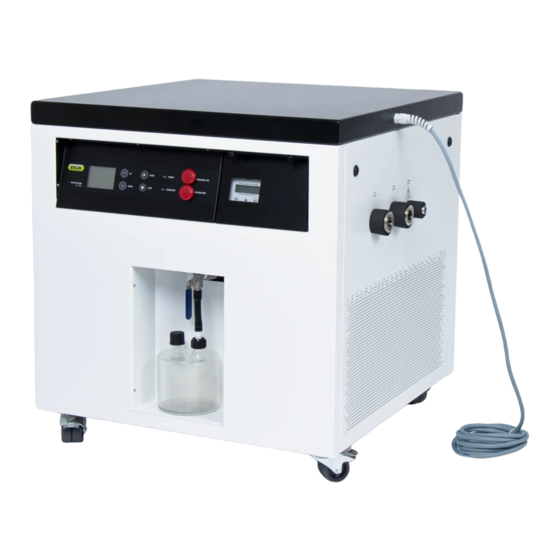
Control elements Oxygen analyzer (See Control elements) (Front cover oxygen analyzer) Communication cable Exhaust connection (marked: Exhaust) Process gas out Process gas in (marked: OUT) (marked: IN) Ventilation area Solvent receiving vessel Castor wheels 10/34 Operation Manual Inert Loop S-395... -
Page 11: Rear View
Signal lamp oxygen Signal lamp operation Switch off Set temperature down 3.2.4 Type plate The type plate identifies the instrument. The type plate is located at the rear side of the instrument. See Side connections Operation Manual Inert Loop S-395 11/34... -
Page 12: Scope Of Delivery
705 x 660 x 705 x 660 x 705 x 660 x 705 x 660 x 705 x 660 x (W x D x H) 687 mm 687 mm 687 mm 687 mm 687 mm 12/34 Operation Manual Inert Loop S-395... - Page 13 22 bar 22 bar 22 bar 22 bar lowable pressure (PS) [Low pres- sure side] Maximum al- 26 bar 26 bar 26 bar 26 bar 26 bar lowable pressure (PS) [High pres- sure side] Operation Manual Inert Loop S-395 13/34...
-
Page 14: Ambient Conditions
PTFE Pipe elbow Stainless steel 1.4307 Pressure switch PVDF, Viton, NBR/aramid fiber composite Oxygen sensor PA, PPS, PTFE, stainless steel Black hoses EPDM Drain tube Woulff bottle Glass Plate heat exchanger Stainless steel solder 14/34 Operation Manual Inert Loop S-395... -
Page 15: Installation Site
— Put the instrument on the castors directly on the floor, do not use a pad. — Make sure the castor brakes are locked. — Place only BUCHI spray dryer on the instrument. — Do not place the instrument near vibration-sensitive devices. -
Page 16: Transport And Storage
Wherever possible, store the instrument in its original packaging. After storage, check the instrument, all seals and tubing for damage and replace if necessary. Moving the instrument Release the castor breaks. Move the instrument to the designated place. Lock the castor breaks. 16/34 Operation Manual Inert Loop S-395... -
Page 17: Installation
Risk of instrument damage because of not suitable power supply cables. Not suitable power supply cables can cause bad performance or an instrument damage Use only BUCHI power supply cables. Precondition: R The electrical installation is as specified on the type plate. -
Page 18: Installing The Solvent Receiving Vessel
Installing the solvent receiving vessel Put the PTFE hose connection on the bottle. Put the solvent receiving vessel in place. Install the PTFE hose onto the condensate drain valve. Open the condensate drain valve. 18/34 Operation Manual Inert Loop S-395... -
Page 19: Installing The Oxygen Sensor For The First Time
Installing the oxygen sensor for the first time The primary installation of the oxygen sensor for a new instrument will be guided by a BUCHI service technician. For further information see Chapter 7.7 "Changing the oxygen sensor", page 27. Installations for a spray drying mode For installations for a spray drying mode, see separate installation manuals. -
Page 20: Operation
Switch on the aspirator. See Operation manual of the connected spray dryer. ð The signal lamp pressure is off. Switch on the spray gas. Wait until the oxygen level is less than 6 %. ð The signal lamp oxygen is off. 20/34 Operation Manual Inert Loop S-395... -
Page 21: Tasks During Spray Drying
Disconnect the power cable. Setting condenser temperature Increase temperature Press the button Set temperature UP. See Chapter 3.2.3 "Control elements", page 11. Decrease the temperature Press the button Set temperature DOWN. See Chapter 3.2.3 "Control elements", page 11. Operation Manual Inert Loop S-395 21/34... -
Page 22: Cleaning And Servicing
Do not carry out any servicing and cleaning operations that involve opening the housing. Use only genuine BUCHI spare parts in order to ensure correct operation and preserve the warranty. Carry out the service and cleaning operations described in this section to extent the lifetime of the instrument. -
Page 23: Cleaning The Housing
To avoid calibration errors, clean ambient air or certified 20.9% level oxygen should be applied to the sensor. If an ambient air calibration is performed, it is recommended that the oxygen level is confirmed by a portable oxygen meter. Operation Manual Inert Loop S-395 23/34... - Page 24 Disconnect the power cable. Disconnect the communication cable, see Chapter 3.2.1 "Front view", page 10. Remove the screws at the indicated positions. Open the front cover oxygen sensor. Remove the grounding cable from the front cover oxygen sensor. 24/34 Operation Manual Inert Loop S-395...
- Page 25 Remove the oxygen sensor. Make sure the O-ring (1) stays in its position. Reconnect the communication cable, see Chapter 3.2.1 "Front view", page 10. Reconnect the sensor cable. Wait 15 minutes for the electronics to warm up. Operation Manual Inert Loop S-395 25/34...
- Page 26 Fit the cable plug on the sensor. Connect the sensor cable by rotating the securing ring of the cable plug. Reconnect the communication cable, see Chapter 3.2.1 "Front view", page 10. Install the grounding cable. 26/34 Operation Manual Inert Loop S-395...
-
Page 27: Checking The Controller Of The Oxygen Sensor
Disconnect the power cable. Disconnect the communication cable, see Chapter 3.2.1 "Front view", page 10. Remove the screws at the indicated positions. Open the front cover oxygen sensor. Remove the grounding cable from the front cover oxygen sensor. Operation Manual Inert Loop S-395 27/34... -
Page 28: Installing The Oxygen Sensor
R There is no oxygen sensor installed. See Chapter 7.7.1 "Removing the oxygen sensor", page 27. R The power cable is disconnected. Install a new O-ring (1). ð The O-ring is seated properly and cannot fall out accidentally. 28/34 Operation Manual Inert Loop S-395... - Page 29 Reconnect the communication cable, see Chapter 3.2.1 "Front view", page 10. Install the grounding cable. Install the front cover. Place the screws at the indicated positions. Connect the power cable. Operation Manual Inert Loop S-395 29/34...
-
Page 30: Help With Faults
Switch off the instrument. overheated Wait until the instrument is in ambient temperature. Remove dust and foreign objects from the ventilation slots using compressed air or a vacuum cleaner. Switch on the instrument. Contact BUCHI Customer Service. 30/34 Operation Manual Inert Loop S-395... -
Page 31: Taking Out Of Service And Disposal
When disposing, observe the disposal regulations of the materials used. Materials used see Chapter 3.4 "Technical data", page 12. Returning the instrument Before returning the instrument, contact the BÜCHI Labortechnik AG Service Department. https://www.buchi.com/contact Operation Manual Inert Loop S-395 31/34... -
Page 32: Appendix
Sealing FKM for hose coupling 11056479 Woulf Bottle 041875 Screw cap SVL 22 003577 Screw cap SVL22 005222 Receiving vessel for solvent 040398 Hose Inert Loop TPR conf. 11071076 Oxygen Sensor S-395 11075130 Shelf life max. 1 year 32/34 Operation Manual Inert Loop S-395... - Page 33 Büchi Labortechnik AG Appendix | 10 Order no. Image O-Ring Ø29.82x2.62 FKM 70 11075133 Vacuum clamp KF 25 11063662 Silicone hose 10x2.0x80 V0 11075249 Operation Manual Inert Loop S-395 33/34...
- Page 34 We are represented by more than 100 distribution partners worldwide. Find your local representative at: www.buchi.com...
Need help?
Do you have a question about the Inert Loop S-395 and is the answer not in the manual?
Questions and answers