Sign In
Upload
Manuals
Brands
Rockwell Automation Manuals
Servo Drives
Allen-Bradley Kinetix 300 2097-V32PR2
Rockwell Automation Allen-Bradley Kinetix 300 2097-V32PR2 Manuals
Manuals and User Guides for Rockwell Automation Allen-Bradley Kinetix 300 2097-V32PR2. We have
1
Rockwell Automation Allen-Bradley Kinetix 300 2097-V32PR2 manual available for free PDF download: User Manual
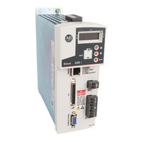
Rockwell Automation Allen-Bradley Kinetix 300 2097-V32PR2 User Manual (234 pages)
EtherNet/IP Indexing Servo Drives
Brand:
Rockwell Automation
| Category:
Servo Drives
| Size: 9 MB
Table of Contents
Table of Contents
3
Preface
9
Summary of Changes
9
Conventions
9
Additional Resources
10
About the Kinetix 300 Drive System
11
Catalog Number Explanation
13
Agency Compliance
14
CE Requirements
14
System Design Guidelines
16
System Mounting Requirements
16
Transformer Selection
17
Circuit Breaker/Fuse Selection
17
Enclosure Selection
19
Power Dissipation Specifications
20
Minimum Clearance Requirements
21
Electrical Noise Reduction
22
Bonding Drives
22
Bonding Multiple Subpanels
24
Establishing the Noise Zones
25
Cable Categories for Kinetix 300 Drive Components
27
Noise Reduction Guidelines for Drive Accessories
27
Mount Your Kinetix 300 Drive
30
Kinetix 300 Drive Connectors and Indicators
32
Safe Torque off Connector Pinout
33
I/O Connector Pinout
34
Motor Feedback (MF) Connector Pinout
35
Ethernet Communication Connector Pinout
35
AC Input Power Connector Pinout
36
Back-Up Power Connector Pinout
36
Shunt Resistor and DC Bus Connector Pinout
36
Motor-Power Connector Pinout
36
Control Signal Specifications
37
Digital Inputs
37
Digital Outputs
42
Analog Reference Input
43
Analog Output
44
Master Gearing/Step and Direction Inputs
45
Buffered Encoder Outputs
46
Ethernet Connections
47
24V DC Back-Up Power
47
Motor Feedback Specifications
48
Motor Feedback Specifications
49
Feedback Power Supply
53
Basic Wiring Requirements
55
Build Your Own Cables
56
Route Power and Signal Wiring
56
Determine the Input Power Configuration
56
Three-Phase Power Wired to Three-Phase Drives
57
Single-Phase Power Wired to Single-Phase Drives
58
Voltage Doubler Operation
58
Isolation Transformer in Grounded Power Configurations
59
Three-Phase Power Wired to Single-Phase Drives
59
Voiding of CE Compliance
61
Ground Your Kinetix 300 Drive System
62
Ground Your Drive to the System Subpanel
62
Ground Multiple Subpanels
63
Power Wiring Requirements
63
Wiring Guidelines
65
Wiring the Kinetix 300 Drive Connectors
66
Wire the Safe Torque off (STO) Connector
66
Wire the Back-Up Power (BP) Connector
66
Wire the Input Power (IPD) Connector
67
Wire the Motor Power (MP) Connector
68
Apply the Motor-Cable Shield Clamp
73
Feedback and I/O Cable Connections
74
Flying-Lead Feedback Cable Pinouts
75
Wiring the Feedback and I/O Connectors
76
Wire the I/O Connector
76
Kinetix 300 Drive (IOD Connector and Terminal Block)
76
Wire the Low Profile Connector Kit
77
Shunt Resistor Connections
78
Ethernet Cable Connections
79
Drive Organizer and Identification
82
Motor Category
82
Synchronous Motor Database
83
Linear Motor Database
84
General Category
85
Communication Categories
89
Ethernet Communication
89
Ethernet/Ip (CIP) Communication
90
Input/Output Categories
91
Digital I/O
91
Analog I/O
92
Limits Categories
93
Velocity Limits
93
Position Limits
94
Dynamics Category
95
Tools Category
96
Monitor Category
97
Faults Category
98
Indexing Category
99
Index Type Parameter
101
Action Parameter
106
Start Index
107
Abort Indexing
107
Reset Index
107
Explicit Messages for Indexing
108
Homing Category
111
Homing Methods
112
Immediate Homing
113
Absolute Homing
113
Home to Marker
114
Home Offset
114
Homing Switch
114
Homing Firmware Algorithm
115
Homing Methods Timing Diagrams
116
Homing Methods 7
116
Homing Method 23
117
Homing Method 25
118
Homing Method 27
119
Homing Method 29
120
Homing Method 33
121
Homing Method 34
121
Homing Method 35
121
Upgrade Firmware
122
Configure and Start up the Kinetix 300 Drive
123
Keypad Input
124
Status Indicators
125
Configure the Kinetix 300 Drive Ethernet/Ip Address
126
Ethernet Connection
126
Kinetix 300 Drive Ethernet Port Configuration
126
Current IP Address Ethernet Setting
127
Configure the IP Address Manually (Static Address)
127
Configure the IP Address Automatically (Dynamic Address)
129
Install the Kinetix 300 Add-On Profile
130
Configuring the Logix Ethernet/Ip Module
131
Configure the Logix Controller
131
Configure the Ethernet Port
132
Configure the Ethernet Module
133
Configure the Kinetix 300 Drive
134
Download the Program
136
Apply Power to the Kinetix 300 Drive
137
Test and Tune the Axis
138
Test the Axis
138
Tune the Axis
139
Select Drive Operating Mode
142
Master Gearing Mode Examples
143
Master Gearing Example 1
143
Master Gearing Example 2
143
Master Gearing Example 3
143
Configure Master Gearing Mode
144
Configure the Drive Parameters and System Variables
145
Tools for Viewing Parameters
145
Tools for Changing Parameters
147
Configure Drive Mode with Explicit Messaging
148
Configure Drive for Linear Motors and Direct Drive Stages
150
Motor Temperature Sensor
150
Understanding Encoder Resolution Setting
150
Change the Encoder Resolution for an Incremental Encoder
151
Safety Precautions
153
General Troubleshooting
154
Display Behavior
154
Error Codes
155
Clearing Faults
158
Use Digital Inputs to Clear Faults
158
Use Drive Parameters to Clear Faults
158
Certification
161
Important Safety Considerations
162
Safety Category 3 Requirements
162
Stop Category Definition
162
Performance Level and Safety Integrity Level (SIL) CL3
162
Description of Operation
163
Functional Proof Tests
163
Troubleshooting the Safe Torque off Function
164
PFD and PFH Definitions
164
PFD and PFH Data
164
Safe Torque off Connector Data
165
STO Connector Pinouts
165
Wiring Your Safe Torque off Circuit
166
European Union Directives
166
Safe Torque off Wiring Requirements
167
Kinetix 300 Drive Safe Torque off Feature
168
Safe Torque off Feature Bypass
168
Kinetix 300 Drive Safe Torque off Wiring Diagrams
169
Safe Torque off Signal Specifications
170
Safety Input and Output Schematics
171
Interconnect Diagram Notes
174
Power Wiring Examples
175
Shunt-Resistor Wiring Example
177
Kinetix 300 Drive/Rotary Motor Wiring Examples
178
Kinetix 300 Drive/Linear Motor Wiring Examples
181
Kinetix 300 Drive/Actuator Wiring Examples
183
Kinetix 300 Drive to Micrologix Controller Wiring Examples
186
Kinetix 300 Drive Master Gearing Wiring Example
187
Motor Brake Currents
188
System Block Diagrams
189
Input and Output Assembly
191
Output Assembly Examples
197
Incremental Position Point-To-Point Profile
198
Velocity Motion Profile
198
Tag Number Descriptions
199
Index Base Addressing
212
Explicit Messaging Data Types
213
Explicit Messaging Data Type Examples
214
DINT Data Type Examples
214
REAL Data Type Examples
215
String Data Type Examples
216
Modes of Operation
219
Overtravel Hardware Inputs
220
Operation
221
Overtravel Fault Recovery
222
Advertisement
Advertisement
Related Products
Rockwell Automation Allen-Bradley Kinetix 300 2097-V32PR0
Rockwell Automation Allen-Bradley Kinetix 300 2097-V32PR4
Rockwell Automation Allen-Bradley Kinetix 300 2097-V31PR0
Rockwell Automation Allen-Bradley Kinetix 300 2097-V33PR1
Rockwell Automation Allen-Bradley Kinetix 300 2097-V33PR3
Rockwell Automation Allen-Bradley Kinetix 300 2097-V33PR5
Rockwell Automation Allen-Bradley Kinetix 300 2097-V33PR6
Rockwell Automation Allen-Bradley Kinetix 300 2097-V34PR3
Rockwell Automation Allen-Bradley Kinetix 300 2097-V34PR5
Rockwell Automation Allen-Bradley Kinetix 300 2097-V34PR6
Rockwell Automation Categories
Controller
Control Unit
Power Supply
DC Drives
Industrial Equipment
More Rockwell Automation Manuals
Login
Sign In
OR
Sign in with Facebook
Sign in with Google
Upload manual
Upload from disk
Upload from URL