
Subscribe to Our Youtube Channel
Related Manuals for Teknik Hythe 5426438


Summary of Contents for Teknik Hythe 5426438
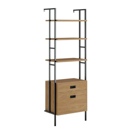
- Page 1 Teknik www.teknikoffice.co.uk Get all organized and stuff . Hythe Wall Mounted 4 Shelf Boookcase with Drawers Model 5426438 02/21/20...
- Page 2 Table of Contents Assembly Tools Required Part Identifi cation No. 2 Phillips Screwdriver Tip Shown Actual Size Hardware Identifi cation Assembly Steps 5-24 Hammer Not actual size Electric drill with 5/16" bit (ONLY in indicated step) Page 2...
-
Page 3: Part Identification
Now you know Part Identifi cation our ABCs. å While not all parts are labeled, some of the parts will have a label or an inked letter on the edge to help distinguish similar parts from each other. Use this part identifi cation to help identify similar parts. SHELF (1) BACK (1) SMALL DRAWER BACK (1) -
Page 4: Hardware Identification
Hardware Identifi cation å Screws are shown actual size. You may receive extra hardware with your unit. (EXTENSION SET SHOWN SEPARATED) EXTENSION RAIL - 2 EXTENSION SLIDE - 2 CABINET RIGHT - 1 CABINET LEFT - 1 FILE ROD - 2 L-WRENCH - 1 HIDDEN CAM - 14 DRAWER RIGHT - 1... - Page 5 Hardware Usage Guide HOW TO USE A HIDDEN CAM & CAM SCREW OR CAM DOWEL NOTE: Various CAM SCREWS or a CAM DOWEL may be used. Turn the CAM SCREW or gently tap the CAM DOWEL until the shoulder is against the surface of the part.
- Page 6 Step 1 Assemble your unit on a carpeted fl oor or on the empty å carton to avoid scratching your unit or the fl oor. Turn two CAM SCREWS (10) into the ENDS (B and C). å Push four HIDDEN CAMS (9) into the ENDS (B and C). å...
- Page 7 Step 2 Separate the EXTENSION SLIDES (2) from the EXTENSION RAILS (1) as å shown in the upper diagram below. Be prepared, the parts are greasy. Remember: Righty tighty. Fasten the EXTENSION RAILS (1) to the ENDS (B and C). Use six 1/2" å...
- Page 8 Step 3 Fasten the CABINET RIGHT (3) to the RIGHT END (C) and å the CABINET LEFT (4) to the LEFT END (B). Use six 1/2" FLAT HEAD SCREWS (20) through the 2nd, 6th and 10th hole from the roller end. Roller end 1/2"...
- Page 9 Step 4 Push two HIDDEN CAMS (9) into the BRACE (F). å Insert a WOOD DOWEL (13) into each END (B and C). å Fasten the ENDS (B and C) to the BRACE (F). Tighten two å HIDDEN CAMS. NOTE: Be sure the WOOD DOWELS in the ENDS insert å...
- Page 10 Step 5 Turn four CAM SCREWS (10) into the SHELF (A). å Insert two WOOD DOWELS (13) into the SHELF (A). å Fasten the SHELF (A) to the ENDS (B and C). Tighten four å HIDDEN CAMS. NOTE: Be sure the WOOD DOWELS in the SHELF insert å...
- Page 11 Step 6 Slide the BACK (G) into the grooves of the ENDS (B and C) å and SHELF (A). Page 11...
- Page 12 Step 7 Insert a WOOD DOWEL (13) into each END (B and C). å Fasten the BOTTOM (H) to the ENDS (B and C). Use four å 1-9/16" LARGE HEAD SCREWS (17). NOTE: Be sure the WOOD DOWELS in the ENDS insert å...
- Page 13 Step 8 Push the tabs of an UPPER FRAME (Q) into the holes in a å LOWER FRAME (R) as shown in the upper diagram. Fasten the UPPER FRAME (Q) to the LOWER å FRAME (R). Tighten four 1/2" HEX HEAD SCREWS (19) using the L-WRENCH (8).
- Page 14 Step 9 Fasten the BOTTOM (H), SHELF (A) and one UPPER å SHELF (S) to the LOWER FRAMES (R). Tighten twelve 1-7/8" HEX HEAD SCREWS (16) using the L-WRENCH (8). Fasten two UPPER SHELVES (S) to the UPPER å FRAMES (Q). Tighten eight 1-7/8" HEX HEAD SCREWS (16) using the L-WRENCH (8).
- Page 15 Step 10 -Carefully stand your unit upright against the wall in its fi nal location. Strike a mark through the center of the hole in å the UPPER FRAMES (Q). Lay your unit down. -Drill a 5/16" hole on the marks. å...
- Page 16 Step 11 Turn four CAM SCREWS (10) into the SMALL å DRAWER FRONT (D). Push four HIDDEN CAMS (9) into the SMALL DRAWER å SIDES (J and K). Arrow Page 16...
- Page 17 Step 12 1-3/16" FLAT HEAD SCREW (4 used in this step) Groove Slide a DRAWER BOTTOM (O) into the grooves in the Fasten the SMALL DRAWER SIDES (J and K) to the å å SMALL DRAWER SIDES (J and K) and SMALL SMALL DRAWER BACK (N).
- Page 18 Step 13 Flip the SMALL DRAWER over. å Fasten the DRAWER RIGHT (5) to the SMALL RIGHT å DRAWER SIDE (K). Use three 1/2" FLAT HEAD SCREWS (20) through the 3rd, 5th, and 8th hole from the roller end. Fasten the DRAWER LEFT (6) to the SMALL LEFT DRAWER å...
- Page 19 Step 14 Turn four CAM SCREWS (10) into the LARGE å DRAWER FRONT (E). Now might be a good time to refresh Push four HIDDEN CAMS (9) into the LARGE DRAWER å your drink. SIDES (L and M). Arrow Page 19...
- Page 20 Step 15 1-3/16" FLAT HEAD SCREW (4 used in this step) F i n i s h r f a Groove Slide the DRAWER BOTTOM (O) into the grooves in Fasten the LARGE DRAWER SIDES (L and M) to the å...
- Page 21 Step 16 Fasten the EXTENSION SLIDES (2) to the LARGE å DRAWER SIDES (L and M). Use six 1/2" FLAT HEAD SCREWS (20). This drawer will accommodate letter size fi les. Place your å fi le hangers (not included) onto the FILE RODS. L e t t e r File Rod...
- Page 22 Step 17 Fasten the PULLS (11) to the DRAWER FRONTS (D and E) å Use four 3/8" MACHINE SCREWS (21). Almost time to celebrate! With a nap. 3/8" MACHINE SCREW (4 used in this step) Page 22...
- Page 23 Step 18 To insert the small drawer into your unit, tip the front of the drawer down and drop the rollers on the drawer behind the å rollers on the unit. Lift the front of the drawer up and slide it into the unit. To insert the large drawer into your unit, line up the EXTENSION SLIDES on the drawer with the EXTENSION RAILS on å...
- Page 24 WARNING Please use your furniture correctly and safely. Improper use can cause safety hazards, or damage to your furniture or household items. Carefully read the following chart. Look out for: What can happen: How to avoid the problem: • Overloaded shelves. •...
Need help?
Do you have a question about the Hythe 5426438 and is the answer not in the manual?
Questions and answers