
Related Manuals for Teknik New Hyde 426440


Summary of Contents for Teknik New Hyde 426440
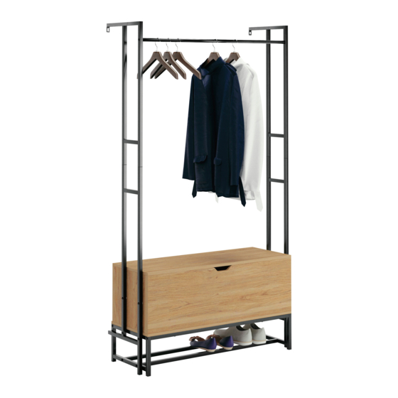
- Page 1 Teknik www.teknikoffice.co.uk You'll love what we have in storage. Hythe Wall Mounted Hallway Storage New Hyde Collection | Model 426440...
- Page 2 Table of Contents Assembly Tools Required Part Identifi cation No. 2 Phillips Screwdriver Tip Shown Actual Size Hardware Identifi cation Assembly Steps 6-21 Electric drill with 5/16" bit (ONLY in indicated step) Page 2...
-
Page 3: Part Identification
Now you know Part Identifi cation our ABCs. å While not all parts are labeled, some of the parts will have a label or an inked letter on the edge to help distinguish similar parts from each other. Use this part identifi cation to help identify similar parts. FRONT (1) TOP (1) LOWER FRAME (2) -
Page 4: Hardware Identification
Hardware Identifi cation å Screws are shown actual size. You may receive extra hardware with your unit. HIDDEN CAM - 4 CAM SCREW - 4 WOOD DOWEL -12 REAR HINGE - 3 APPLIQUE CARD - 1 RIGHT HINGE - 1 BUMPER CARD - 1 LEFT HINGE - 1 WALL ANCHOR - 2... - Page 5 Hardware Identifi cation å Screws are shown actual size. You may receive extra hardware with your unit. 1-3/16" HEX HEAD SCREW - 18 2" PAN HEAD SCREW - 2 1-9/16" PAN HEAD SCREW - 12 1/2" HEX HEAD SCREW - 8 1-3/8"...
- Page 6 Hardware Usage Guide HOW TO USE A HIDDEN CAM & CAM SCREW OR CAM DOWEL NOTE: Various CAM SCREWS or a CAM DOWEL may be used. Turn the CAM SCREW or gently tap the CAM DOWEL until the shoulder is against the surface of the part.
- Page 7 Step 1 Assemble your unit on a carpeted fl oor or on the empty å carton to avoid scratching your unit or the fl oor. Just think. The sooner you do this, the sooner Turn four CAM SCREWS (2) into the FRONT (A). å...
- Page 8 Step Step 2 Insert two WOOD DOWELS (3) into the FRONT (A). å Fasten the ENDS (B and C) to FRONT (A). Tighten four å HIDDEN CAMS. NOTE: Be sure the WOOD DOWELS in the FRONT insert å into the ENDS. Notch Finished edge Page 8...
- Page 9 Step Step 3 Insert two WOOD DOWELS (3) into the ENDS (B and C). å Fasten the BACK (D) to the ENDS (B and C). Use four å 1-9/16" PAN HEAD SCREWS (15). NOTE: Be sure the WOOD DOWELS in the ENDS insert å...
- Page 10 Step Step 4 Carefully turn your unit on its top edges. å These holes are further from this edge Insert eight WOOD DOWELS (3) into the SHELF (E). å Fasten the BOTTOM (E) to the FRONT (A), ENDS (B and C), å...
- Page 11 Step Step 5 Carefully turn your unit onto the BACK (D). å Fasten the REAR HINGES (4) to the BACK (D). Use nine å BLACK 9/16" PAN HEAD SCREWS (16). 9/16" PAN HEAD SCREW (9 used in this step) Page 11...
- Page 12 Step Step 6 Fasten the TOP (F) to the BACK (D). Use six 9/16" PAN å HEAD SCREWS (16). 9/16" PAN HEAD SCREW (6 used in this step) Page 12...
- Page 13 Step Step 7 IMPORTANT: You will need someone's help in this step. å Fasten the LEFT HINGE (5) to the LEFT END (B) and the å RIGHT HINGE (6) to the RIGHT END (C). Use four 9/16" PAN HEAD SCREWS (16). Fasten the LEFT HINGE (5) and RIGHT HINGE (6) to å...
- Page 14 Step Step 8 Fasten the LEGS (G and H) to the BRACES (J) å and RACK (K). Tighten eight 1-3/16" HEX HEAD SCREWS (12) using the L-WRENCH (11). NOTE: You should start each SCREW a few turns before å completely tightening any of them. Surface with fewer holes Surface with more holes 1-3/16"...
- Page 15 Step Step 9 Fasten the BRACES (J) to the BOTTOM (E). Tighten four å 1-3/16" HEX HEAD SCREWS (12) using the L-WRENCH (11). Now might be a good time to refresh NOTE: You should start each SCREW a few turns before å...
- Page 16 Step Step 10 Fasten a LOWER FRAME (L) and WASHERS (10) to the å LEFT END (B) and LEFT LEG (G). Tighten two 1-3/16" HEX HEAD SCREWS (12) and two 1-3/8" HEX HEAD SCREW (17) as shown using the L-WRENCH (11). NOTE: You should start each SCREW a few turns before å...
- Page 17 Step Step 11 Fasten the remaining LOWER FRAME (L) and WASHERS (10) to å the RIGHT END (C) and RIGHT LEG (H). Tighten two 1-3/16" HEX HEAD SCREWS (12) and two 1-3/8" HEX HEAD SCREW (17) as shown using the L-WRENCH (11). NOTE: You should start each SCREW a few turns before completely å...
- Page 18 Step Step 12 Fasten the ROD (N) to the UPPER FRAMES (M). å Tighten two 1-3/16" HEX HEAD SCREWS (12) using the L-WRENCH (11). NOTE: You should start each SCREW a few turns before å completely tightening any of them. 1-3/16"...
- Page 19 Step Step 13 Fasten the UPPER FRAMES (M) to the LOWER FRAMES (L). Tighten å eight 1/2" HEX HEAD SCREWS (14) using the L-WRENCH (11). If you're doing this to help a friend, don't NOTE: You should start each SCREW a few turns before completely å...
- Page 20 Step Step 14 -Carefully stand your unit upright against the wall in its fi nal location. Strike a mark through the center of the hole in å the UPPER FRAMES (M). Lay your unit down. -Drill a 5/16" hole on the marks. å...
- Page 21 Step Step 15 Peel APPLIQUES from the APPLIQUE CARD (8) and stick them onto each visible HIDDEN CAM. å Peel the BUMPERS from the BUMPER CARD (7) and stick them onto the top edges of the ENDS (B, and C) where å...
- Page 22 WARNING Please use your furniture correctly and safely. Improper use can cause safety hazards, or damage to your furniture or household items. Carefully read the following safety information. Death or serious injury may occur when children climb on furniture. A remote control, toys or other items placed on the furniture may encourage a child to climb on the furniture which could cause it to tip-over and result in serious injury or death.
Need help?
Do you have a question about the New Hyde 426440 and is the answer not in the manual?
Questions and answers