Table of Contents
Advertisement
Advertisement
Table of Contents
Troubleshooting

Related Manuals for Steris OT1000 Series


Summary of Contents for Steris OT1000 Series
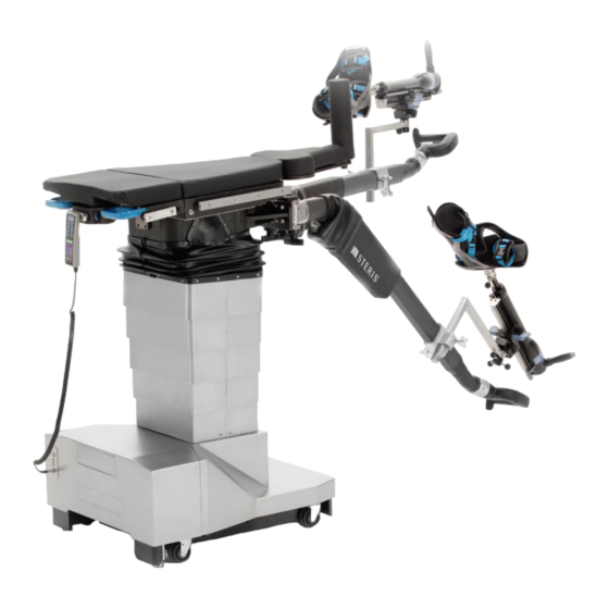
- Page 1 OPERATOR MANUAL OT1000 Series Orthopedic Surgical Tables (Rev G) 10008511...
- Page 3 Complete instructions for uncrating have been furnished. If missing, contact STERIS for a replacement copy, giving the serial, equipment and model numbers of the unit. STERIS carries a complete line of accessories for use with this table. STERIS representatives will gladly review these with you. Advisory...
- Page 4 STERIS maintains a global staff of well equipped, factory-trained technicians to provide these services, as well as expert repair services.
-
Page 5: Table Of Contents
TABLE OF CONTENTS Section Number Description Page Safety Precautions ........................1-1 Symbols on Table ..........................1-5 Symbols on Hand Control ........................1-7 Screen Graphics on LCD Display ......................1-9 Operating Instructions ........................2-1 Table Preparation ..........................2-1 Floor Locks ............................2-3 Level All Table Function ........................ - Page 6 TABLE OF CONTENTS (CONT’D) Section Number Description Page Technical Specifications ........................5-2 5.5.1 Overall Size (W x L x H)....................... 5-2 5.5.2 Range of Motion........................... 5-2 5.5.3 EMC ............................. 5-3 5.5.4 High-Frequency Interference ...................... 5-3 5.5.5 Weight ............................5-4 5.5.6 Power Requirements........................5-4 5.5.7 Environmental Conditions ......................
- Page 7 The OT1000 Series Orthopedic Surgical Tables Range of Motion (Typical)........5-6 Figure 5-3. The OT1000 Series Orthopedic Surgical Tables Tabletop Dimensions (Typical) ......5-7 Figure 5-4. The OT1000 Series Orthopedic Surgical Tables Image Amplification Coverage (Typical) ..5-7 Figure 5-5. Install/Remove Battery Fuse (Typical)..................5-9 Figure 5-6.
- Page 8 10008511 Operator Manual Table of Contents...
- Page 9 LCD Display Screen Alarm Chart....................3-3 Table 4-1 Replacement Parts.......................... 4-9 Table 5-1 OT1000 Series Orthopedic Surgical Tables Accessories* ............5-16 Table A-1 Guidance and Manufacturer’s Declaration – Electromagnetic Emissions – For All Equipment and Systems (per IEC 60601-1-2 Clause 5.2.2.1 c) Table 1 ......A-2 Table A-2 Guidance and Manufacturer’s Declaration –...
- Page 10 viii 10008511 Operator Manual Table of Contents...
-
Page 11: Safety Precautions
SAFETY PRECAUTIONS The following Safety Precautions must be observed when operating or servicing the OT1000 Series Orthopedic Surgical Tables. WARNING indicates the potential for personal injury and CAUTION indicates the potential for damage to equipment. For emphasis, certain Safety Precautions are repeated throughout the manual. It is important to review ALL Safety Precautions before operating or servicing the unit. - Page 12 If the integrity of the external protective ground installation or arrangement is in doubt, operate the table from its internal power source. If an antistatic path is necessary, STERIS recommends antistatic pads in direct contact with the patient. Table must also be positioned on antistatic floor or connected to equalization device (equipotential connector).
- Page 13 WARNING – INSTABILITY HAZARD: Possible patient or user injury, as well as table or accessory failure, may result from using STERIS table accessories for other than their stated purpose – or from using, on STERIS tables, accessories manufactured and sold by other companies.
- Page 14 Route the hand control cord clear of any pinch points where cord could be damaged. Use of incorrect hydraulic oil may severely damage the table and/or cause malfunction. Contact STERIS for proper hydraulic oil. After performing cleaning procedures, ensure pads and tabletop are completely dry before reinstalling.
-
Page 15: Symbols On Table
Table operation may still occur with orange wrench displayed. 1.1 Symbols on Table Table 1-1 is a key to the symbols appearing on the OT1000 Series Orthopedic Surgical Tables. Table 1-1. Definition of Symbols on Surgical Table Symbol... - Page 16 Table 1-1. Definition of Symbols on Surgical Table (Cont’d) Symbol Definition Control Power ON Control Power OFF Powered By AC Attention, Consult Manual for Further Instructions Amperage Rating of the Unit Voltage Rating of Unit Alternating Current Frequency Rating of Unit Power Rating Serial Number of the Unit IPX4...
-
Page 17: Symbols On Hand Control
Leg Spar Control Enable Drive Femur Positioner Foot Control 1.2 Symbols on Hand Table 1-2 is a key to the symbols appearing on the OT1000 Series Orthopedic Surgical Tables Primary Hand Control. Control Table 1-2. Definition of Symbols on Hand Control Symbol... - Page 18 Table 1-2. Definition of Symbols on Hand Control (Cont’d) Symbol Definition HEIGHT DN Tabletop Down (Height Dn; Lower) TREND Move Tabletop into Trendelenburg REVERSE TREND Move Tabletop into Reverse Trendelenburg FLOOR Floor Lock Function LOCK FLOOR UNLOCK Floor Unlock Function UNLATCH Lateral Slide Unlock LEVEL TILT...
-
Page 19: Screen Graphics On Lcd Display
1.3 Screen Graphics Table 1-3 is a key to the graphics appearing in the OT1000 Series on LCD Display Orthopedic Surgical Tables Hand Control LCD Display. NOTE: Refer to 5.7.2, H LCD D ECTION ONTROL ISPLAY , for table operation using hand control LCD display. - Page 20 Table 1-3. Definition of Hand Control LCD Display Screen Icons (Cont’d) Symbol Definition Table Trendelenburg and Tilt Position. ° = Angles Displayed in Degrees. See Operator Manual for More Information. 1-10 10008511 Operator Manual Safety Precautions...
-
Page 21: Operating Instructions
NOTE: Uses other than as specified and described in this section are not recommended and may not be safe. The OT1000 Series Orthopedic Surgical Tables are to be operated only by users who have successfully completed an Operator Training Course or In-Service. For specific set-ups, refer to the Set-Up Guide (10014249). Please contact STERIS for appropriate guidance, in-service and training. - Page 22 Prepare the OT1000 Series Orthopedic Surgical Tables for operation as follows: NOTE: Before using table, ensure no visible table damage. 1. Review Pinch Point Warnings as presented in 5.1, P ECTION INCH of this manual. OINT ARNINGS ® 2. This table is equipped with INTELLIPOWER dual power system.
-
Page 23: Floor Locks
2.2 Floor Locks Operate the OT1000 Series Orthopedic Surgical Tables floor locks as follows: WARNING – TIPPING NOTE: Before Floor Locks can be disengaged, the following must HAZARD: Do not release floor take place: locks while patient is on table. -
Page 24: Level All Table Function
2.3 Level All Table Ensure the OT1000 Series Orthopedic Surgical Table is ready for operation as follows: Function NOTE: Lateral slide must be manually adjusted to center (see 2.4, L , for more information). ECTION ATERAL LIDE UNCTION 1. Ensure Head Section is level. -
Page 25: Figure 2-3. Tabletop Lateral Slide Function (Typical)
2.4 Lateral Slide Ensure the OT1000 Series Orthopedic Surgical Table is ready for operation as follows: Function NOTE: Lateral Slide is a manual function. However, tabletop must be Unlatched and Tilt leveled before manual buttons are available. 1. Ensure Head Section is level. -
Page 26: Femur Positioner Control
2.5 Femur Positioner Ensure the OT1000 Series Orthopedic Surgical Table is ready for operation as follows: Control NOTE: Verify Femur Positioner is properly attached to table (refer to Femur Positioner IFU, 10015643). 1. Ensure Head Section is level. 2. Verify table batteries are charged and table is ON (refer to... -
Page 27: Leg Spar Usage
2.6 Leg Spar Usage Ensure the OT1000 Series Orthopedic Surgical Tables is ready for operation as follows: WARNING – PERSONAL NOTE: If necessary, verify Femur Accessory is properly attached to INJURY HAZARD: table (refer to Femur Positioner IFU, 10015643). • Following leg spar 1. -
Page 28: Figure 2-6. Table Power Drive Feature
2.7 Table Power Drive Ensure the STERIS OT1100 or OT1200 Orthopedic Surgical Table is ready for operation as follows: Feature 1. Ensure Head Section is level. WARNING – PERSONAL 2. Unplug table from facility power. INJURY HAZARD: 3. Verify table batteries are charged and table is ON (refer to •... -
Page 29: Figure 2-7. Leg Spars In Storage Position
NOTE: Table coasts to a stop within 8’ (2.4 m) after short friction braking when rocker switch is released. This table may be “power braked” to stop within 2’ (0.6 m) by releasing ENABLE DRIVE button, or by reversing direction of rocker switch. WARNING –... - Page 30 2-10 10008511 Operator Manual Operating Instructions...
-
Page 31: Troubleshooting
(see Table 3-1 Table 3-2). If you STERIS-trained service can not solve the situation, call STERIS* and give the following personnel. Maintenance information for the table: model number, serial number, date of performed by unqualified purchase. -
Page 32: Table 3-1 Troubleshooting Chart
(no load/nonuse) drops to 22 V or less for five minutes. Press any button on hand control but STOP. Faulty Primary Hand Control* – replace. Faulty table board or program – call STERIS. † Wrong hand control software – call STERIS. †... -
Page 33: Table 3-2 Lcd Display Screen Alarm Chart
Protection fuse not installed or has failed. missing or bad connection. Wrench, Red Ensure fuse is installed or replace fuse. (CHECK BATTERY FUSE) Battery ICON Assess battery condition. Call STERIS. with Orange ! ALARM – Charging circuit Orange Call STERIS. failure (Power Supply or P6 Wrench, Red cable or main board defect). - Page 34 If error repeats, call overtemperature. (DRIVE STERIS. OVERHEATING) ALARM – Control PC Board Orange Wrench Call STERIS. Have Control PC Board battery failure (not installed, lithium real time clock battery replaced. bad or bad contact). (REAL- TIME) ALARM – Communication...
- Page 35 Orange Wrench MOSFET driver failure (replace Master commands solenoid to open Control Board) or valve related failure. Call but feedback says solenoid STERIS. is closed. (NONE) ALARM – Tilt left driver Orange Wrench MOSFET driver failure (replace Master commands solenoid to close Control Board) or valve related failure.
- Page 36 NUMBER ALARM – Femur down driver Orange Wrench MOSFET driver failure (replace Master commands direction control Control Board). Call STERIS. to open but feedback says solenoid is closed. (NONE) ALARM – Femur down driver Orange Wrench MOSFET driver failure (replace Master commands direction control Control Board).
- Page 37 OUTPUT FAILED) ALARM – Height up direction Orange Wrench MOSFET driver failure (replace Master driver is turned on but Control Board). Call STERIS. feedback says output is off. (NONE) ALARM – Height up direction Orange Wrench MOSFET driver failure (replace Master driver is turned off but Control Board).
- Page 38 (DISPLAY) NUMBER ALARM – Height down Orange Wrench MOSFET driver failure (replace Master direction driver is turned on Control Board). Call STERIS. but feedback says output is off. (NONE) ALARM – Height down Orange Wrench MOSFET driver failure (replace Master direction driver is turned off Control Board).
-
Page 39: Routine Maintenance
Contact STERIS for details. result in costly damage. Maintain a record of all maintenance procedures performed on an Contact STERIS regarding OT1000 Series Orthopedic Surgical Table. If a problem occurs, refer service options. 3, T , or contact STERIS. -
Page 40: Cleaning Table
2) The use of H2O2 + PAA (Hydrogen Peroxide + Peracetic Acid) sufficient cleaning/ is strongly discouraged for use on all STERIS products. disinfection properties. 3) Always follow manufacturer instructions for concentrations and use of cleaning products. - Page 41 To ensure prolonged use of STERIS mattresses and pads, abide by following cleaning instructions: 1. Inspect mattress prior to and/or after use to check for mattress integrity. 2. Follow cleaning frequency per facility protocol; however, clean all stains promptly. 3. Use hospital-grade low-level disinfectant cleaning agent appropriate for soft materials.
-
Page 42: After Each Usage
4.2.2 After Each Usage After each use of an OT1000 Series Orthopedic Surgical Table, clean/disinfect as follows: WARNING – INFECTION NOTE: Ensure all protective covers are installed over any open HAZARD: To protect against receptacles. aerosols being reflected from potentially contaminated 1. -
Page 43: End-Of-Day Cleaning Procedure
At the end of each day, perform the cleaning procedures as outlined Procedure 4.2.2, A ECTION FTER SAGE 4.2.4 Weekly Cleaning After each weekly use of an OT1000 Series Orthopedic Surgical Table, clean/disinfect table as follows: Procedure 1. Perform Steps 1 through 4 of 4.2.2, A ECTION FTER CAUTION –... -
Page 44: Bi-Weekly Maintenance
Never permit inexperienced, unqualified persons to attempt to make any repairs to the table. 4.5 Monthly Check OT1000 Series Orthopedic Surgical Tables casters and floor locks for any accumulated debris and clean as follows: Maintenance 1. Ensure floor locks are properly engaged. - Page 45 Lead acid batteries last longer if not fully discharged. Therefore, to obtain the longest life and capacity from the OT1000 Series Orthopedic Surgical Table batteries, always connect ac power cord to table base and plug into an appropriate ac receptacle as often as possible (especially overnight), and as long as possible, with the Main Power Switch set to ON.
-
Page 46: Preventive Maintenance Schedule
Maintenance Manual. personnel or installation of 4. Preventive Maintenance is essential in keeping this equipment in unauthorized parts could optimal working condition. STERIS recommends establishing an cause personal injury, annual maintenance agreement with STERIS service. result in improper 5. -
Page 47: Replacement Parts
3. Send your order directly to STERIS. NOTE: For Replacement Parts, note the following: 1) Use only STERIS authorized parts on the equipment. Use of unauthorized parts will void the warranty. 2) This table uses lead-acid batteries. Lead-acid batteries normally are subject to self-discharge and battery-life deterioration in long- term storage. -
Page 48: Level Check
Trendelenburg/Reverse Trendelenburg. NOTE: The LCD Display pictorials and values change accordingly. 5. Use a level and ensure tabletop is level. If not, call STERIS. 4.10 Override Hand Check the OT1000 Series Orthopedic Surgical Table Override Hand Control as follows: Control Check 1. -
Page 49: Supplemental Information
Do not exceed the lowest weight limit, table or accessory. WARNING – TIPPING The OT1000 Series Orthopedic Surgical Tables are designed to safely HAZARD: support a 500 lb (227 kg) patient. Do not exceed the maximum •... -
Page 50: Patient Safety Straps
CAUTION – POSSIBLE EQUIPMENT DAMAGE: OT1000 Series Orthopedic Surgical Table is designed primarily for hip Appropriate components of and lower extremity procedures: hip pinning, ender nailing, this surgical table have been intramedullary nailing of the femur, tibia and fibula surgery. -
Page 51: Emc
Should user experience Tables. interference, relocate this • OT1000 Series Orthopedic Surgical Tables should not be used device or minimize the use of adjacent to or stacked with other equipment. If so, table should the affected equipment while be observed to verify normal operation. -
Page 52: Weight
NOTE: Each table is shipped from the factory configured to the electrical requirement specified on the factory order. If this electrical configuration needs to be changed in the field, consult STERIS for the needed procedure and required materials. 5.5.7 Environmental Temperature: 63 –... - Page 53 Ground Equalization Terminal (Male Connection) Leg Spar Control Primary Fuses Leg Spar Main Power Switch Femur Positioner (If Equipped) Facility Power Cord Connection Primary Hand Control Power Cord Figure 5-1. The OT1000 Series Orthopedic Surgical Tables Components (Typical) Supplemental Information Operator Manual 10008511...
- Page 54 30° 75° 15° (102) (102) 20° 45° 90° 15° 15° Dimensions are typical - Dimensions are inches (mm). drawing is not to scale. Figure 5-2. The OT1000 Series Orthopedic Surgical Tables Range of Motion (Typical) 10008511 Operator Manual Supplemental Information...
-
Page 55: Essential Performance
(508) Area Dimensions are typical - drawing is not to scale. Figure 5-4. The OT1000 Series Orthopedic Surgical Tables Image Amplification Coverage (Typical) 5.5.11 Essential Performance Essential Performance for Surgical Tables: 1) Support a patient without unwanted movement under single fault conditions. -
Page 56: Installation Instructions
NOTE: If table is going to be stored for more than three months, remove fuse to limit battery discharge. 3. The OT1000 Series Orthopedic Surgical Tables are equipped with ® INTELLIPOWER dual power system modes. If table is to be operated on battery power, proceed to Step 8. -
Page 57: Figure 5-5. Install/Remove Battery Fuse (Typical)
Figure 5-5. Install/Remove Battery Fuse (Typical) NOTE: A green Main Power Switch indicates facility power is available to the OT1000 Series Orthopedic Surgical Table. A symbol on the LED Display indicates the batteries are charging. Refer to 4.6, B... -
Page 58: Figure 5-6. Connect Facility Power And Primary Hand Control To
(when unlocked) and four hours of nonuse (when locked). The Buttons Description hand control is reactivated by depressing ANY button but STOP. WARNING – PERSONAL The OT1000 Series Orthopedic Surgical Table is equipped with a INJURY AND/OR primary hand control (see Figure 5-7). -
Page 59: Primary Hand Control
LEVEL ALL ON - Press any key except STOP OFF - Press STOP key Figure 5-7. OT1000 Series Orthopedic Surgical Tables Primary Hand Control TREND: When touch pad is depressed, the head end of the tabletop lowers; or, foot end raises. The LCD Display TREND value changes accordingly. -
Page 60: Hand Control Lcd Display Description
Figure 5-8) as follows: NOTE: Simply release the hand control soft key or touch pad when desired OT1000 Series Orthopedic Surgical Table position has been reached and table automatically stops and locks in position. See 5.5.2, R , for the positioning of the following... -
Page 61: Override Hand Control
(when unlocked) and four hours of nonuse (when locked). The hand control is reactivated by depressing ANY button but STOP. 5.8 Override Hand The OT1000 Series Orthopedic Surgical Tables are equipped with a Backup Control System. System consists of Override Hand Control, Control Foot Pump and Foot Pedal. -
Page 62: Override Hand Control Description
(Figure 5-10): NOTE: Simply release the override hand control touch pad when desired OT1000 Series Orthopedic Surgical Table Tabletop position has been reached and table will automatically stop and lock in position. 5.5.2, R , for the positioning of the table... -
Page 63: Figure 5-10. Override Hand Control
Figure 5-10. Override Hand Control REVERSE TREND: While depressed and pumping simultaneously, the head end of the tabletop rises; or, foot end lowers. TILT LEFT: While depressed and pumping simultaneously, the tabletop rolls to the left (patient's left or viewing the table from the head end). -
Page 64: Return Backup Control System
2. To remove pads, gently “peel” pad away from tabletop. 5.10 Accessories/Side The standard STERIS permanently attached 3/8" wide x 1-1/8" tall (9.5 x 28.6 mm) side rails allow for the use of many standard surgery table Rails attachments and accessories. The rails consist of one rail mounted to each side of each tabletop main section. -
Page 65: Disposal Hazards
(Cu), and copper alloys (Cu/x), plastic, synthetic rubber, and/or cause malfunction. plating (Cr, Ni, Zn, Au) and adhesives not known to require special Contact STERIS for proper disposal methods at date of this manual. hydraulic oil. Hydraulic Oil: contained in hydraulic components located in the base, column and hydraulic system lines and hoses. - Page 66 5-18 10008511 Operator Manual Supplemental Information...
-
Page 67: Emc Compliance Technical Data
Portable RF communications equipment (including peripherals such as antenna cables and external antennas) should be used no closer than 30 cm (12”) to any part of the OT1000 Series Surgical Table, including cables supplied by STERIS. Otherwise, degradation of the performance of this equipment could result. -
Page 68: Table A-1 Guidance And Manufacturer's Declaration - Electromagnetic Emissions
Table A-1. Guidance and Manufacturer’s Declaration – Electromagnetic Emissions – For All Equipment and Systems (per IEC 60601-1-2 Clause 5.2.2.1 c) Table 1 The OT1000 Series Orthopedic Surgical Table and related components are intended for use in the electromagnetic environment specified below. -
Page 69: Ot1000 Series Orthopedic Surgical Table
Systems (per IEC 60601-1-2 Clause 5.2.2.1 f) Table 2 The OT1000 Series Orthopedic Surgical Tables and related components are intended for use in the electromagnetic environment specified below. The Customer or the user should ensure this OT1000 Series Orthopedic Surgical Tables is used in such an environment. -
Page 70: Table A-3 Guidance And Manufacturer's Declaration - Electromagnetic Immunity For Equipment
Systems That Are Not Life-Supporting (per IEC 60601-1-2 Clause 5.2.2.2) Table 4 The OT1000 Series Orthopedic Surgical Table and related components are intended for use in the electromagnetic environment specified below. The Customer or the user should ensure this OT1000 Series Orthopedic Surgical Table is used in such an environment. -
Page 71: Table A-4 Recommended Separation Distances Between Portable And Mobile Rf Communications
Equipment and OT1000 Series Orthopedic Surgical Table (per IEC 60601-1-2 Clause 5.2.2.2) Table 6 The OT1000 Series Orthopedic Surgical Table and related components are intended for use in the electromagnetic environment in which radiated RF disturbances are controlled. The Customer or the user can help prevent... - Page 72 10008511 Operator Manual Appendix...
Need help?
Do you have a question about the OT1000 Series and is the answer not in the manual?
Questions and answers