Table of Contents
Advertisement
Quick Links
No. DOC1023125
NN58170201
PRODUCT NAME
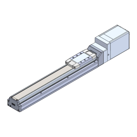
e-Actuator / Slider type
Electric Actuator
Easy to Operate Integrated Controller
(
)
servo 24VDC
Model / Series / Product Number
EQFS series
Also check the e-Actuator setup software(e-Actuator setup tool)instruction manual.
Please download this software from our website.
http://www.smcworld.com/
Advertisement
Table of Contents

Related Manuals for SMC Networks EQFS Series


Summary of Contents for SMC Networks EQFS Series
- Page 1 / Slider type Electric Actuator Easy to Operate Integrated Controller ( ) servo 24VDC Model / Series / Product Number EQFS series Also check the e-Actuator setup software(e-Actuator setup tool)instruction manual. Please download this software from our website. http://www.smcworld.com/...
-
Page 2: Table Of Contents
Contents Safety Instructions ..............3 Precautions for product specific ..............5 1 Outlines of Product ............23 1.1 System configuration example ............23 1.2 Features ..................... 24 1.3 How to Order ................... 25 1.4 Specification Table ................26 1.5 Construction .................... 27 1.6... - Page 3 4.4 Methods of interrupting operation ..........52 5 Alarm detection ..............53 5.1 Parallel signal output for the alarm group ......53 5.2 Alarm details ................... 53 6 Troubleshooting ............... 57 7 Specifications ..............62 7.1 Basic specifications of the product ..........62 7.2...
-
Page 4: Safety Instructions
e-Actuator/ Slider Type Safety Instructions These safety instructions are intended to prevent hazardous situations and/or equipment damage. These instructions indicate the level of potential hazard with the labels of “Caution,” “Warning” or “Danger.” They are all important notes for safety and must be followed in addition to International Standards (ISO/IEC) , and other safety regulations. - Page 5 e-Actuator/ Slider Type Safety Instructions Caution The product is provided for use in manufacturing industries. The product herein described is basically provided for peaceful use in manufacturing industries. If considering using the product in other industries, consult SMC beforehand and exchange specifications or a contract if necessary.
-
Page 6: Precautions For Product Specific
Precautions for product specific Precautions for wiring and cable Warning ① Adjustment, installation, inspection, or wiring changes should be conducted after the power supply to this product has been turned off. Electrical shock, malfunction, or damage can result. ② Never disassemble the cable. ③... - Page 7 ⑪ The speed and force may change depending on the cable length, load, and mounting conditions. Furthermore, if the cable length exceeds 5 m, then it will decrease by up to 10% for every additional 5 m.(If cable length is 15m: Maximum 20% reduction.) ⑫...
- Page 8 ⑨ Do not use the stop signal as the emergency stop of the system. Stop by shutdown of M24V is for stopping the electric actuator with deceleration. For the emergency stop of the equipment, design the system with a separate emergency stop circuit conforming to relevant safety standards.
- Page 9 ⑤ Prevent the seizure of rotating parts (pins, etc.) by ap- plying grease. ⑥ Do not use the product until you verify that the equipment can operate properly. After mounting or repair, connect the power supply to the product and perform appropriate functional inspections to check it is mounted properly.
- Page 10 ⑤ When installing, adjusting, inspecting or performing maintenance on the product, controller and related equipment, be sure to shut off the power supply to them. Then, lock it so that no one other than the person working can turn the power on, or implement measures such as a safety plug. ⑥...
- Page 11 Caution ① Conduct the following inspection before operation. a) Confirm that the power supply line and each signal line is not damaged. b) Play and looseness of the connector to each power line and signal line c) Play and looseness of the mounting d) Confirm that the electric actuator/cylinder/controller/driver is operating correctly.
- Page 12 【 】 Unpackaging Caution ① Check the received product is as ordered. If the different product is installed from the one ordered, injury or damage can result. ■ Operating environment Warning ① Avoid use in the following environments. 1. Locations where a large amount of dust and cutting chips are airborne. 2.
- Page 13 ③ Install the electric actuator and its peripheral devices on a fire-proof material. Direct installation on or near a flammable material may cause a fire. ④ Do not install the product in a place subject to vibrations and impacts. It will cause failure or malfunction. ⑤...
- Page 14 ⑥ Take measures against drops and check that safety is assured before mounting, adjustment and inspection of the product. If the lock is released with the product mounted vertically, a work piece can drop due to its weight. ⑦ When the actuator is operated manually, supply 24VDC to the [LK RLS] terminal of the power supply connector.
- Page 15 ■ Handling Caution ① OUT output signal 1) Positioning Operation When the actuator moves to within a set range using parameter 【OUT output signal with】, the output signal, INP, will be turned on. Set to [0.50] or higher. It may cause malfunction. ②...
- Page 16 ■ Mounting Caution ① Design the installation so that the temperature surrounding the actuator is 40oC or less. ② Keep the flatness of mounting surface to within [0.1mm or less for length 500mm]. Insufficient flatness of the work piece or the surface onto which the actuator body is to be mounted can cause play in the guide and increased sliding resistance.
- Page 17 Body mounting example For bottom of housing B Body mounting reference plane Positioning pin position (Mounting reference plane) Body mounting Positioning pin position reference plane (Mounting reference plane) Positioning pin position Positioning pin position (Bottom of housing B) Body mounting reference plane is the datum level for running parallelism. If the running parallelism of the table is required, install it by pressing the datum level against parallel pins or the like.
- Page 18 ■ Maintenance Caution ① Cut the power supply during maintenance and replacement of the product. 【 Maintenance frequency 】 Preform maintenance according to the table below. Please contact SMC if there are any problems. Appearance Frequency Internal check Belt check check 〇...
- Page 19 d. Vertical line of belt teeth Flaw which is made when the belt runs on the flange. e. Rubber back of the belt is softened and sticky f. Crack on the back of the belt ■ How to detach and attach the dust seal band For the internal-check as the maintenance, the method of detaching and attaching the dust seal band is shown as the following.
- Page 20 【Mounting】 【 Dis-assembly 】 The re-assembly is completed by the reverse procedure of “Dis-assembly” sections ①, ② and ③. Model Type of bolt Bolt size Model Type of bolt Bolt size EQFS25 EQFS25 M3x20 Round head Cross recessed EQFS32 M3x6 EQFS32 M4x30 combination screw...
- Page 21 ④ "Pulley plate" is installed. (Refer to the table below) Bolt Tightening Model Thread size torque [Nm] EQFS25 EQFS32 0.36±10% EQFS40 - 20 -...
- Page 22 Specific precautions for Battery-less absolute encode Warning ① Do not use in an environment where a strong magnetic fields are present. A magnetic sensor is used in the encoder. Therefore, if the actuator motor is used in a strong magnetic field environment, malfunction or failure may occur.
- Page 23 The motors of the electric actuator can be installed close to each other. Caution ① Supply power when the actuator is stationary. The electric actuator acquires the absolute position data from the absolute encoder when power is applied. Therefore, if the power is applied to the controller when the actuator is moving with an external force, the controller fails to acquire the absolute position data, which generates an alarm.
-
Page 24: 1 Outlines Of Product
1 Outlines of Product 1.1 System configuration example An example of a system configuration using the controller is shown below. ●PLC *3) (Provided by customer) ●IO cable *1) Part no.:JX-CI□-E-□-S ●PC *2)*3) (Provided by customer) ●Communication cable /USB cable *1) Part no.:JX-CT-E Setup Communication cable... -
Page 25: Features
1.2 Features Features of the electric actuator. ● Electric actuator control Positioning operation and operation at a specific speed and force of the actuator are possible by controlling the Step motor (24 VDC servo). ● Alarm detection function Abnormal conditions are automatically detected. Alarms are output via CC-Link communication. The alarm history can be stored in the controller memory. -
Page 26: How To Order
1.3 How to Order How to order is shown below. Applicable stroke table Stroke [mm] Size 1000 1100 1200 ● ● ● ● ● ● ● ● ● ● ● ● ● ● ● ● ● ● ● ● ● ●... -
Page 27: Specification Table
1.4 Specification Table Battery-less absolute encoder type (Step motor 24 VDC) Model EQFS25 EQFS32 EQFS40 Stroke[mm] Note1) 50 to 800 50 to 1000 150 to 1200 Horizontal 39.5 Work load [kg] Note.2) Vertical 12.5 to 400 20 to 1200 12 to 850 6 to 450 3 to 225 24 to 1100 16 to 750 8 to 450 4 to 125 30 to 1200 20 to 1000 10 to 500 5 to 225... -
Page 28: Construction
1.5 Construction When "Without" is selected for the grease application Comprnent Parts Description Material Remarks Description Material Remarks End cover Aluminum alloy Anodized Motor Body Aluminum alloy Anodized Connector Rail Guide Band stopper Stainless steel Ball screw assembly Dust Seal Band Stainless steel Table Aluminum alloy... -
Page 29: Accessories
1.6 Accessories Table spacer(Parallel motor only) Model Part name EQFS25(L/R) EQFS32(L/R) Table spacer EQFS40(L/R) Optional parts (sold separately) ・Power supply cable ・Parallel I/O cable ・Communication cable ・USB cable ・Setup software Refer to 9 Optional parts (sold separately) for details of optional parts. - 28 -... -
Page 30: 2 Installation And Initial Setting
2 Installation and Initial Setting 2.1 Flow from installation to initial setting Be sure to check the procedure below before use. Procedure 1 Preparation →Item2.2 ① Checking the contents of the package *:Please confirm that all packaging, accessories, and optional items are present. →Item2.3... -
Page 31: Check The Contents Of The Packag
2.2 Check the contents of the packag After unpacking everything, check the description on the label to identify the actuator and the number of accessories. If any parts are missing or damaged, please contact your distributor. Product Name and Number Quantity Electric actuator 1 pcs. -
Page 32: Preparation Of Necessary Supplies
2.3 Preparation of necessary supplies Please prepare the following items for installation and wiring. ・Wiring cable ・M4 screw ・ Cable with crimping terminal ・Toothed washer ・Switch (24 VDC, contact capacity of 0.5 A or more):For lock release Please provide the following equipment to run the system. ・24 VDC power supply ・... -
Page 33: Installation Of Electric Actuators
2.4 Installation of electric actuators Install the electric actuator at the installation location using the following method. (1) Mounting Refer to Electric actuators / Common precautions in Precautions for product specific for information on bolts and fastening torques to be used for mounting workpieces and tools and for mounting the main unit. -
Page 34: Wiring And Connection
2.5 Wiring and Connection Please prepare electric actuator. Connect the cable to the connector part of the electric actuator. Setup Communication connector Power supply connector Parallel I/O connector 2.5.1 Connection to input power supply Input power supply Electric actuator 24VDC Power supply cable (Power supply (24 VDC) and wires must be prepared by the user.) - Page 35 2) Wiring of the stop switch (EMG) When applying 24V to M24V electric wire, the product starts operating. When 24V is shut off, Servo OFF activates and the product stops operating. Stop switch must be installed by the user to stop the actuator in abnormal situations for this M24V wire.
- Page 36 (2) Wiring of shutdown circuit Design the circuit so that M24V is turned off when the stop switch and ALARM are turned off. (see P.36 Fig.1-1 and Fig.1-2 for circuit example) Operation resumes when the stop is released.Please release the stop after fully confirming safety. The operation when the stop is released differs depending on the mode.
- Page 37 Fig.1-1 Circuit example(for NPN type) Fig.1-2 Circuit example(for PNP type) - 36 -...
- Page 38 Fig. 2-1 Circuit example (for NPN type) Example where operation is not restarted when double solenoid mode stop is released. Fig. 2-2 Circuit example (for PNP type) Example where operation is not restarted when double solenoid mode stop is released) Set the timer setting value to 0.5 seconds or more.
-
Page 39: Connection To Pc
2.5.2 Connection to PC Connect the setup communication cable to the communication connector of the electric actuator and the PC. ・Setup communication cable part number (with A-miniB type USB cable): JX-CT-E ン Electric actuator Setup communication cable USB cable (A-miniB type) (PC is prepared by the user.)... - Page 40 ●NPN type ●PNP type Input power Input power supply supply 24VDC 24VDC IO connecter IO connecter RESET RESET (Unused) (Unused) Not connected. Not connected. Load Load OUT0 OUT0 Load Load OUT1 OUT1 Load Load OUT2 OUT2 Load Load ALARM ALARM Caution The parallel input/output of this electric actuator is of non-insulated specification.
-
Page 41: Power On Alarm (Error)
2.6 Power ON alarm (error) Check that there is no problem with each wiring referring to 2.5 Wiring and connection of electric actuator and supply 24 VDC power supply between C24V - 0V (power supply input for control) and between M24V - 0V (power supply input for power line) of the power supply cable. Status status Normal... -
Page 42: Test Run
■ Settings and Data Entry Setup of the operation data is required using the setup software to move the electric actuator to the specified position. The data entered using the setup software is stored in the memory of the electric actuator. -
Page 43: 3 Operation
3 Operation 3.1 Operation flow The startup procedure varies depending on the power-on situation. Procedure1 Startup ●When turning on the power supply normally after shipped from SMC ●When supplying power again after resetting the alarm Group E or after changing the parameter of "return to the origin direction"... -
Page 44: Procedure For Power Set Up
3.2 Procedure for power set up 3.2.1 Procedure for power start up The following is a Startup procedure for the battery-less absolute encoder for every occasion that occurs when the power is applied (1) When turning on the power supply normally after shipped from SMC (2)... - Page 45 Return to the origin operation is required when the alarm Group E is generated and the alarm is reset due to power supply shutdown or when the "return to the origin direction" parameter is changed. - Procedure - -Timing chart- 1.
-
Page 46: Operation Instructions
3.3 Operation Instructions 3.3.1 Outline of operation command Operation command can be provided by the operation data pre-registered in the electric actuator using the parallel I/O signal. The operation procedure differs according to the control mode. There are two operation patterns with the operation data. ・Positioning operation ・Pushing operation There are three control modes. - Page 47 (2) Positioning operation by double solenoid mode - Procedure (Double solenoid mode) - 1. Specify and command operation using the operation data by turning IN0 and IN1 inputs ON. ⇒ Load the specified operation data → Command to move to the origin end IN0 input: ON (IN1: OFF) →...
- Page 48 (3) Positioning operation by closed center mode - Procedure (Closed center mode) - 1.Specify and command operation using the operation data by turning IN0 and IN1 inputs ON/OFF. ⇒ Load the specified operation data. IN0 input: ON (IN1: OFF) → Command to move to the origin end IN1 input: ON(IN0: OFF) →...
-
Page 49: Reset
3.3.3 Reset Alarm reset - Timing chart alarm reset- - Procedure - (1) Alarm is generated (*ALARM output turns OFF.) ↓ (2) Turn the RESET input ON. ↓ (3) The *ALARM output turns ON when the generated alarm is of the alarm Groups B to D and the cause of the alarm is solved. -
Page 50: Operation Examples
3.4 Operation Examples 3.4.1 Positioning operation Example) A setting example in the double solenoid mode is described when it is moved from the origin end (0 mm position) to the opposite end (100 mm position) with the speed of 100 mm/s (operation command to the opposite end) and then moved from the opposite end (100 mm position) to the origin end (0 mm position) with the speed of 300 mm/s (operation command to the intermediate point). -
Page 51: 4 Operation Mechanism
4 Operation Mechanism 4.1 Positioning operation When a check mark is entered with the setup software in the "Positioning operation" of the operation data, the positioning operation will be set and it will move to the position set as the "origin end, opposite end, intermediate... -
Page 52: Return To The Origin
4.2 Return to the origin The operation to return to the origin is required in the events described below. (1) Motor is replaced (2) When the alarm "Group E" is generated and reset the alarm by turning on the power supply again. (3) The "return to the origin direction"... -
Page 53: Response Time In Receiving An Electric Actuator Input Signal
4.3 Response time in receiving an electric actuator input signal Factors of the response delay to the electric actuator input signal are described below. (1) Delay in electric actuator input signal scan (2) Delay in analysis and computing of the input signal (3) Delay in analysis and processing of the command Make sure to have intervals of 15 ms or longer (30 ms is recommended) between input signals and maintain the state of the signal for the same period of time because delay in PLC processing and... -
Page 54: 5 Alarm Detection
5 Alarm detection The details of the alarm can be checked using the setting software. Refer to the operation manual of the setup software for the alarm checking method. When an alarm is generated, deactivate the alarm after troubleshooting and correcting the error with reference to 5.2 Alarm details. - Page 55 <Condition> - When changing the parameter "Rotating direction reference" -When alarm group E has occurred. In the above, the alarm occurs when JOG or Inching teaching is indicated Return to origin from this setting software (e-Actuator setup tool) at the actuator power is position is Input switched on again.
- Page 56 <Condition> The control power The control power supply voltage is out of the specified range. supply voltage is Input outside the RESET specification <Countermeasure> Check the voltage supplied to the control power supply (C24V). (147) <Condition> An overload condition continued for a certain time. Large current was applied for a Input...
- Page 57 <Condition> Please contact SMC when this alarm is generated. (049) (051) (103) (109) (153) (193) <Countermeasure> (197) Please contact SMC when this alarm is generated. (198) (202) Warning Thoroughly check safety before resetting the alarm since the operation described below will be performed according to the mode immediately after the alarm is reset by RESET.
-
Page 58: 6 Troubleshooting
6 Troubleshooting Refer to the table below for troubleshooting. When the causes in the troubleshooting table cannot be identified and normal operation can be recovered only by replacing the product, the product itself is probably out of order. The product failure may be due to the operating conditions (application). Please contact SMC for assistance. - Page 59 Problem Problem Investigation method and Possible Problem Countermeasures possible causes causes Check the voltage and current supplied to Is the green LED on the the electric actuator. Power fault electric actuator ON? ⇒ 2.5.1 Connection to input power supply Check if the wiring is connected correctly or if there is broken wire or short-circuit by LED is OFF.
- Page 60 When the unlock switch is If there is no sound of lock release from the electric Lock release actuator with lock, the lock may be broken. If the turned ON or OFF there is an error problem persists, please contact SMC. unlocking sound made.
- Page 61 Make sure to have intervals of 15 ms or longer (30 ms is recommended) between input signals and maintain the state of the signal for the same period Check the timing of the signal because delay in PLC processing and electric Signal timing from the PLC to the electric actuator control part scan can occur.
- Page 62 Check the max. speed and acceleration speed of the electric actuator and be sure to input the correct Check that the parameter Incorrect parameters. parameters values are correct. ⇒ 2.7 Setup of the operation parameters ⇒8 Setting In case of such operation, the actuator may start Check if a trapezoidal slowing down before it reaches the maximum Operation...
-
Page 63: 7 Specifications
7 Specifications 7.1 Basic specifications of the product Basic specifications of the product are shown below. Basic specifications of the product are shown below. Item Specification Controlled motor Step motor (servo 24 VDC ) Note1)2) Power supply voltage:24VDC±10% Power supply 【for both of motor drive power control power, stop, lock brake release】... -
Page 64: Parts Description
7.2 Parts Description Details of the parts of the electric actuator. ④ ③ ② ① ⑦ ⑥ ⑤ Viewed from A A side Item Details Drive terminal ① Piston rod Loads and transfers workpieces, etc. Power supply Power supply ON/No alarm: Green LED is ON ②... -
Page 65: Power Supply Connector Specification
7.3 Power supply connector Specification Connect the power supply cable (JX-CD*-E-*-S) to the power supply connector. Tighten the socket with 0.6 N·m when connecting the power supply cable to the power supply connector. Specifications of the power supply cable are described below. Power supply cable (Straight connector type/JX-CDS-E-*-S)... -
Page 66: I/O Connector Specification
7.4 I/O connector specification Connect the I/O cable (JX-CI*-E-*-S) to the parallel I/O connector. Tighten the socket with 0.6 N·m when connecting the I/O cable to the parallel I/O connector. Specifications of the I/O cable are described below. I/O cable (Straight connector type/JX-CIS-E-*-S) I/O cable (Angled connector type/JX-CIA-E-*-S) Electric actuator (I/O connector) side Higher-level device (PLC, etc.) side... - Page 67 - Output side - *When green is the I/O cable (JX-CI*-E-*-S) Wire Signal Terminal Description color name The condition where the OUT0, OUT1, and OUT2 outputs turn ON differs when the commanded operation data are for the positioning operation or the pushing operation.
-
Page 68: Parallel Input/Output Specification
7.4.2 Parallel input/output specification ● Input specification ● Output specification Items Specification Items Specification Input circuit insulation method Non-insulated Output circuit Non-insulated insulation method Number of inputs 3 points Number of outputs 4 points Input voltage 24 VDC +/- 10 (%) Load voltage 24 VDC +/- 10 (%) Input current when ON... -
Page 69: 8 Setting
8 Setting 8.1 Operation data Operation data is the setting for operating the electric actuator. The example shown below is the operation data setting example for the single solenoid mode and double solenoid mode using the e-Actuator setup tool/setup software. In the closed center mode, the operation data setting screen for the intermediate point is added in the operation condition. - Page 70 Details of operation data Name Input range Description "Maximum speed" Sets the speed for moving to the target position or the start between the minimum Speed position for the pushing operation. value and basic (Unit: mm/s) Note 1) parameter "Maximum acceleration/deceleratio Sets the acceleration to reach the moving speed.
-
Page 71: Parameter
8.2 Parameter Setting of operation condition and other conditions of the electric actuator. Caution Write the parameter when the electric actuator is stopped. Details of parameters The parameters can be set using the setup software e-Actuator SETUP tool. Write column: ◎ = Effective immediately after writing in the electric actuator, ○ = Effective when the power supply is turned on again Default value Setting... - Page 72 Caution - The direction in which the electric actuator returns to its origin depends on the electric actuator and the "rotation direction reference" parameter. lf movement is obstructed during return to origin, normal return to origin will not be possible. Therefore, make sure that there are no obstacles or loads within the movable range before returning to origin so that the actuator can perform full stroke operation.
-
Page 73: 9 Optional Parts
9 Optional parts (sold separately) Optional parts described below are available (sold separately). ・Power supply cable ・I/O cable ・Setup communication cable ・e-Actuator setup tool/setup software (download from SMC webpage) 9.1 Power supply cable JX-CD□-E-□-S Cable length (L[m]) *The terminal on PLC Straight connector type/JX-CDS-E-*-S (45.8) Connector type... -
Page 74: Setup Communication Cable
9.3 Setup communication cable JX-CT-E-S *A set of the setup communication cable and USB cable. To e-Actuator (Single:LEC-W2-U)USB cable Communication Cable for Setting (Single:JX-CTC-E-S) ・Setup software (e-Actuator setup tool) (e-Actuator setup tool) - USB driver Please download from SMC website. https://www.smcworld.com/ 9.4... - Page 75 Revision history 4-14-1, Sotokanda, Chiyoda-ku, Tokyo 101-0021 JAPAN Tel: + 81 3 5207 8249 Fax: +81 3 5298 5362 URL https://www.smcworld.com Note: Specifications are subject to change without prior notice and any obligation on the part of the manufacturer. © 2023SMC Corporation All Rights Reserved №DOC1023125...
Need help?
Do you have a question about the EQFS Series and is the answer not in the manual?
Questions and answers