
Related Manuals for SMC Networks E-MY2B Series


Summary of Contents for SMC Networks E-MY2B Series
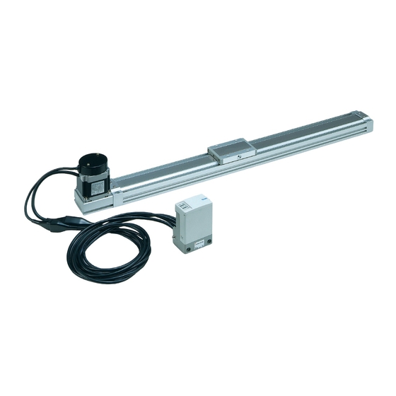
- Page 1 e-Rodless Actuator E-MY2B Series Suitable for light-load transfers. Combined with various guide types. Workpiece applied directly Supported by guides E-MY2B E-MY2B Workpiece Workpiece Guide LC3F2 E-MY 1089...
- Page 2 Floating Bracket Stroke Easy connection to an external guide. Two mounting directions are available. Adjusting Unit Side Support The cylinder tube can be fixed from upward or downward. Controller No Programming Required Realizes similar controllability by simple commands as a pneumatic cylinder.
- Page 3 Remote Control Type Easy to reset after installation as a result of the remote controller. Suited for installing where it is difficult to reach because the controller can be operated in an easily accessible location. Cable length is selectable from 1 m, 3 m and 5 m. °C (Actuator unit only) Improvement in the maximum operating temperature from 40°C to Mounting method can be selected among 3 types.
- Page 4 E-MY2B Series For e-rodless actuator series E-MY2C/H/HT, Model Selection 1 refer to page 1113. Selection Flow Chart Operating conditions Re-examine the operating conditions. m: Load mass (kg) L : Stroke (mm) t : Target of tact time (sec) Change the model. Tentative selection of model Refer to the guideline when the model is temporarily chosen.
- Page 5 Model Selection Guide Tact Time Heavy load Standard load Medium load Light load specifications (2.45 m/s specifications (4.90 m/s specifications (9.80 m/s specifications (19.60 m/s 300 mm/s 300 mm/s 300 mm/s 300 mm/s 1000 1000 1000 1000 1000 1000 1000 1000 Stroke (mm) Stroke (mm)
- Page 6 Model Selection Types of Load Mass and Moment Applied to Rodless Actuators Multiple moments may be generated depending on the mounting orientation, load, and position of the center of gravity. Coordinates and moments Load mass and static moment Horizontal mounting Ceiling mounting Wall mounting : Yawing...
- Page 7 E-MY2B Series Model Selection 2 The following are steps for selection with series E-MY2B best suited for your application. Calculation of Guide Load Factor 1 Operating Conditions Mounting Orientation Note) Regarding the speed and Operating cylinder E-MY2B16-500 acceleration setting, se- 1.
- Page 8 Model Selection Calculation of Guide Load Factor 4 Calculation of Load Factor for Dynamic Moment Load F at acceleration and deceleration = m x a = 4 x 4.9 = 19.6 (N) : Moment at 600 mm/s) = 1.45 (N m) ..........max (From 4 of graph M –3 = —...
- Page 9 LC3F2 E-MY 1097...
- Page 10 e-Rodless Actuator E-MY2B Series Basic Type / Nominal Size: 16, 25 How to Order Integrated E-MY2B 16 M9BW control type Remote E-MY2B 16 M9BW control type Nominal size ∗ Speed specifications [mm/s] Stroke Made to Order 10 to 1000 Refer to “Standard (Refer to page 1099.) Medium 50 to 1000...
- Page 11 -Rodless Actuator E-MY2B Series Basic Type Basic Specifications E-MY2B Model 10 to 1000 mm/s Transfer speed set Medium 50 to 1000 mm/s range Standard 100 to 1000 mm/s Heavy load Standard load Medium load Light load Transfer speed acceleration set range 0.25 to 2.45 m/s 0.49 to 4.90 m/s...
- Page 12 E-MY2B Series Dimensions: Integrated Control Type E-MY2B Nominal size Stroke Nominal size: A clearance of 40 mm or greater (74.7) 101.7 is required. (34) 74.7 Motor 32.5 4 x M5 x 0.8 depth 8 2 x 2 x ø9.5 counterbore depth 5.4 Controller 140 + Stroke...
- Page 13 -Rodless Actuator E-MY2B Series Basic Type Dimensions: Remote Control Type (Actuator unit) E-MY2B Nominal size Stroke ∗ Refer to page 1102 for dimensions of remote controller. Nominal size: (60) (34) (74.7) (101.7) 2 x 2 x ø9.5 counterbore 74.7 depth 5.4 Motor ø5.5 through hole 4 x M5 x 0.8...
- Page 14 E-MY2B Series Dimensions: Remote Control Type (Remote controller unit) Controller Encoder cable on controller side (4 wires) Motor cable on controller side (6 wires) Note 3) Noise filter 200 or less To actuator Power supply cable (2 wires) FG terminal M3 Extention cable A dimension 1000 Note 1)
- Page 15 -Rodless Actuator E-MY2B Series Basic Type Stroke Adjusting Unit E-MY2B-A16A 34.5 4 (Max. 8) Side Support Side support A MY-S25A ø9.5 ø5.5 Side support B MY-S25B LC3F2 M6 x 1 E-MY 1103...
- Page 16 E-MY2B Series Floating Bracket MYAJ25 Note) Mounting direction q and w are available for this model. Application Application Mounting direction q (to minimize the installation height) Mounting direction w (to minimize the installation width) Workpiece Workpiece Guide Guide E-MY2B Floating mechanism Series E-MY2B Series...
- Page 17 -Rodless Actuator E-MY2B Series Basic Type Names and Functions of Individual Part Integrated control type Remote control type Encoder cable on Power supply cable Motor actuator side Controller Encoder cable on cable I/O cable controller side Encoder connector Slider Power supply cable Motor cable on Motor cable on...
- Page 18 E-MY2B Series Internal Circuits and Wiring Examples 3-point Stoppable Type Power Supply Cable NPN input/output circuit 2-core AWG20 (20 wires/0.16 mm Power Power supply supply Symbol Color Signal name Contents switch cable Brown DC1 (+) Power supply DC1 (+) Brown Power supply cables for for driving Blue DC1 (-)
- Page 19 -Rodless Actuator E-MY2B Series Basic Type Error Display and Problem Solving Light OFF Blinks Light ON When the error indicator is displayed, refer to the following instructions. Item Display Contents Solution Item Display Contents Solution If any foreign materials Confirm the power sup- are observed, remove Either the emergency them and then press...
- Page 20 E-MY2B Series Auto Switch Specifications Note) The operating range is a guide including hysteresis, but is not guaranteed. There may be large variations (as Auto Switch Proper Mounting Position (at Stroke End Detection) much as ±30%) depending on the ambient environment. Center of magnet D-M9 , D-M9 V D-A9, D-A9 V...
- Page 21 E-MY2B Series M a d e t Made to Order Specifications: O r d e r Please consult with SMC for detailed dimensions, specifications and delivery. Helical Insert Thread Specifications -X168 The mounting threads of the slider are changed to helical insert threads.
- Page 22 E-MY2B Series e-Rodless Actuators Precautions 1 Be sure to read before handling. Design and Selection Mounting Warning Caution 1. Conduct operation at regulated voltage. 1. Do not drop, strike, or apply excessive shock to the actuator. The product may not function correctly or the controller sec- tion may be damaged if used with any other voltage than the The actuator could be damaged, resulting in its failure and or specified regulated voltage.
- Page 23 E-MY2B Series e-Rodless Actuators Precautions 2 Be sure to read before handling. Wiring Adjustment and Operation Warning Warning 3. Perform wiring when the power is off. 1. Do not short the loads. The controller section may be damaged and malfunction. Short on the load of the controller indicates an error, but it may cause over current and damage the controller.
Need help?
Do you have a question about the E-MY2B Series and is the answer not in the manual?
Questions and answers