Table of Contents
Advertisement
Quick Links
No. DOC1020530
NN57821800
Operation Manual
(Simplified edition)
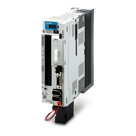
PRODUCT NAME
AC Servo Motor Driver
(
Network card type
)
MODEL / SERIES / PRODUCT NUMBER
LECSN-T□ Series
When connecting LECSN-T with MR Configurator2
TM
, please select the model: "MR-J4-TM".
For SMC products, please contact the SMC sales office.
Advertisement
Table of Contents

Subscribe to Our Youtube Channel
Related Manuals for SMC Networks LECSN-T Series


Summary of Contents for SMC Networks LECSN-T Series
- Page 1 No. DOC1020530 NN57821800 Operation Manual (Simplified edition) PRODUCT NAME AC Servo Motor Driver ( Network card type ) MODEL / SERIES / PRODUCT NUMBER LECSN-T□ Series When connecting LECSN-T with MR Configurator2 , please select the model: "MR-J4-TM". For SMC products, please contact the SMC sales office.
-
Page 2: Table Of Contents
CONTENTS Introduction ........................5 1.Functions and Configuration ................5 2. Wiring ..........................6 2.1 Power supply wiring ..................6 2.2 I/O signal connection ................... 8 2.3 Forced stop deceleration function ............. 9 3. Startup ......................... 10 3.1 Startup procedure..................10 3.2 Procedures for actuator operation ............ - Page 3 6.1.4 Saving of waveform.......................... 32 6.2 Display All Monitor List................33 7. Network setting ...................... 34 7.1 EtherCAT Communication ................. 34 7.1.1 EtherCAT Network card (LEC-S-NE) ..................34 7.1.2 EtherCAT Communication setting ..................35 EtherNet/IP ....................36 7.2.1 EtherNet/IP Network card (LEC-S-N9) .................. 36 7.2.2 EtherNet/IP Communication setting ..................
- Page 4 LECS Series / Driver Safety Instructions These safety instructions are intended to prevent hazardous situations and/or equipment damage. These instructions indicate the level of potential hazard with the labels of “Caution,” “Warning” or “Danger.” They are all important notes for safety and must be followed in addition to International Standards (ISO/IEC), and other safety regulations.
- Page 5 LECS Series / Driver Safety Instructions Caution The product is provided for use in manufacturing industries. The product herein described is basically provided for peaceful use in manufacturing industries. If considering using the product in other industries, consult SMC beforehand and exchange specifications or a contract if necessary.
-
Page 6: Introduction
Introduction This manual is intended for first-time users of LECSN-T servo motors and contains important excerpts from the "LECSN-T Operation Manual”. For details, please prepare the "LECSN-T Operation Manual" and check it as well. For details on the handling of devices other than this driver, refer to the operation manuals of the devices. Refer to Chapter 2 for wiring, Chapter 4 for parameter settings, Chapter 5 for test operation, Chapter 7 for network settings, and Chapter 8 for operation method on the host side. -
Page 7: Wiring
2. Wiring 2.1 Power supply wiring Wires the power supplies for the actuator and driver. This wiring is common in each mode. (1) Using 3-phase 200 V AC to 240 V AC power supply for LECSN2-T Note 1. Between P3 and P4 is connected by default. 2. - Page 8 (2) Using 1-phase 200 V AC to 240 V AC power supply for LECSN2-T Note 1. Between P3 and P4 is connected by default. 2. Always connect between P+ and D terminals. (Factory-wired) 4. If disabling ALM (Malfunction) output with the parameter, configure up the power supply circuit which switches off the magnetic contactor after detection of alarm occurrence on the upper side.
-
Page 9: I/O Signal Connection
2.2 I/O signal connection An example of driver input/output signal connection is shown below. (1) For sink I/O interface Note 1. To prevent an electric shock, always connect the protective earth (PE) terminal (marked ) of the driver to the protective earth (PE) of the cabinet. -
Page 10: Forced Stop Deceleration Function
(2) For source I/O interface POINT For notes, refer to section (1) 2.3 Forced stop deceleration function The following is an explanation of the driver's forced stop deceleration signal EM2. When EM2 is turned off, dynamic brake will start to stop the servo motor after forced stop deceleration. During this sequence, the display shows [AL. -
Page 11: Startup
3. Startup The following are the procedures for startup, actuator operation, and startup of the setup software. 3.1 Startup procedure This section shows the startup procedure when installing the actuator for the first time. For details, refer to "LECSN-T Operation Manual, Section 4.1”. Wiring check Refer to “Chapter 2 Wiring”... -
Page 12: Procedures For Actuator Operation
3.2 Procedures for actuator operation The following is the procedure for actuator operation. (1) Power on When the main and control circuit power supplies are turned on, "b01" (for the first axis) appears on the driver display. When the absolute position detection system is used in a rotary servo motor, first power-on results in [AL. -
Page 13: Setup Software
3.3 Setup software (MR Configurator2 *1 Setup software version 1.52E or above is required. *2 MR Configurator2 (LEC-MRC2E) must be purchased as an additional item. *3 The USB cable (LEC-MR-J3USB) must be purchased as an additional item. 3.3.1 Installation method Perform installation according to the “MR Configurator2 instruction manual”... -
Page 14: System Settings
3.3.3 System settings From “Project” menu select “New”, the “New project” window will be displayed. ① 3.3.4 Model selection ① The Mitsubishi Electric Corporation series will be displayed in the model selection list. Please select the model “MR-J4-TM”, if using the LECSN-T. Please select the station for the USB connection. -
Page 15: Driver On Line Check
3.3.5 Driver ON LINE check Check that the driver is enabled (ONLINE). Check that the “ONLINE / OFFLINE” icon is displayed “ ”. It is OFFLINE when displayed as “ ”. * For OFFLINE, PC and driver aren’t communicating. Confirm the following points. - Is driver's power supply turning on? - Are PC and driver connected with the USB cable? - Is the USB driver installed? -
Page 16: Parameter Setting
4. Parameter setting Parameters that need to be set at startup. For some items, please refer to the recommended parameter values for each actuator in "LECSN-T□ Operating Manual, Appendix 9”. For details and parameters other than those in this section, refer to "LECSN-T□ Operation Manual, Chapter 5”. -
Page 17: Operation Mode【Pr. Pa01
4.1 Operation mode【Pr. PA01】 Select the control mode to be used. For more information, please refer to section 8.1.3 of this manual. POINT Symbols in the network column indicate the following networks. ECT: EtherCAT EIP: EtherNet/IP PNT: PROFINET [Pr. PA01] Control mode setting EtherCAT... -
Page 18: Regenerative Option【Pr. Pa02
4.2 Regenerative option【Pr. PA02】 Set this parameter when the regenerative power generated is large and the driver's built-in regenerative resistor does not have sufficient regenerative capability. For the regenerative option to be used, refer to the "Speed – Workload Graph / Required Conditions for Regeneration Option"... -
Page 19: Auto Tuning Mode【Pr.pa08
4.6 Auto tuning mode【Pr.PA08】 The driver has a built-in real-time auto-tuning function that estimates the machine characteristics (load inertia moment ratio) in real time and automatically sets the optimum gain according to that value. This function facilitates gain adjustment of the driver. The parameters that are automatically adjusted differ depending on the gain adjustment mode. -
Page 20: Parameter Setting By Mr Configurator2
4.8 Parameter setting by MR Configurator2 ① From the “Parameter” menu select “Parameter Setting”, the “parameter setting” window will open. ② The explanation of the parameter item is displayed in “MR2 Help”. (When it is not displayed, from the “View” menu select “Docking window” – “Docking Help”.) ①... -
Page 21: Parameter Reading
4.8.1 Parameter reading If you read the parameters of the driver to the software, please do the “read” operation. ① From the View menu bar "parameter (A)" - please click on the "parameter setting (P)". "Parameter Settings" screen will display. ②... -
Page 22: Test Operation
5. Test operation Using a PC and setup software (MR Configurator2 ), JOG operation, positioning operation, program operation, output signal (DO) forced output, and single-step feed can be executed. This chapter describes JOG operation and positioning operation. For other functions and details, please refer to “Section 4.5.1 of the LECSN-T Operation Manual”. (a) Jog operation Jog operation can be performed without using the upper side. -
Page 23: Jog Mode
5.2 JOG Mode JOG operation can be executed without host command. Use this function with the forced stop disabled. (1) The “JOG Mode” window can be displayed by selecting “Jog Mode” from the “Test Mode” menu in the setup software. (2) Click “OK”. -
Page 24: Positioning Mode
5.3 Positioning Mode ① From the Test Mode menu of the Setup Software select Positioning Mode. The Move Distance Unit Selection window opens. ② Click OK. (When using this function, external input signal operation will be disabled. When controlling from a PLC or upper-level device, the power must be turned off and then on.) ③... -
Page 25: Positioning Mode
5.3.1 Positioning Mode ① To prevent accidental impact at the end of the stroke, operate the actuator at a low speed initially. When changing speed or movement, increase the values whilst checking operation (Change motor speed, acceleration/deceleration time, movement distance values if required). ②... -
Page 26: Motor Speed Configuration
5.3.2 Motor speed configuration Rotation Speed Configuration> < ① Motor speed (r/min) configuration. * r/min (rpm): Indicated motor rotation speed (motor rotations/min) Rotation speed must be between 0 and the allowable speed limit for each actuator. Please be aware that the actuator will not operate if this is set to 0. If the rotation speed is too low, this may cause vibration;... -
Page 27: Acceleration/Deceleration Time Configuration
5.3.3 Acceleration/deceleration time configuration < Acceleration/deceleration time Configuration> ① Acceleration/deceleration time (ms) configuration: The acceleration/deceleration time sets the amount of time (ms) in which a prescribed rotation speed(3000[r/min]) is reached. The acceleration/deceleration time must be set to a value between 0 and the allowable acceleration/deceleration speed for each actuator. -
Page 28: Move Distance Configuration And Operation
5.3.4 Move distance Configuration and Operation < Move distance Configuration> ① Set the move distance [pulse]. Select a value within the stroke range. ② Actuator position will operate using [Forward (CCW)], [Reverse (CW)]. The position at which power is turned ON will be set as the home position, and the actuator will travel the amount set as move distance (check wiring and parameters If operation is not performed correctly).When performing positioning operation in the setup software, the rotation direction of the actuator does not change if you change the setting of parameter PA14 (Rotation direction selection). -
Page 29: Monitor By Mr Configurator
6. Monitor by MR Configurator 2 The setup software (MR Configurator2 ) allows the user to acquire the operating waveforms and status of the electric actuator. 6.1 Acquisition of motion waveform with graph monitor With the setup software (MR Configurator2 : LEC-MRC2E) monitor graph function, the motion waveform during electric actuator operation can be obtained as described below. -
Page 30: Under The Setting Tab: Setting Of The Items To Display The Graph
6.1.1 Under the setting Tab: Setting of the items to display the graph Set the items to display analogue and digital waveform, trigger conditions and time for the horizontal axis of the graph. Click the [Setting] tab of the [Setting] window to set the items to display the waveform, trigger conditions and horizontal axis of the graph. - Page 31 (2) Trigger “Trigger” is a condition which decides the display timing of the graph. If trigger conditions are not satisfied, waveform will not be displayed. ① Click “ “ of [Data] to set the condition. (In general, set the Motor speed.) ①...
-
Page 32: Trigger Wait
6.1.2 Trigger wait When the “Start” button is clicked, the screen will be on stand-by. When trigger conditions are satisfied during the trigger wait, waveforms can be captured and displayed. Click the “Start” button every time measurement fresh capture is required. (The advantage of this method of capturing the waveform is a waveform will not be updated in the case of an incorrect operation.) ①... -
Page 33: Operation Instruction
6.1.3 Operation Instruction When the PLC on the master side sends the operation command, the actuator will operate. When the trigger conditions in 6.1.1 (2) are satisfied, the operation waveforms can be captured. When the time set in 6.1.1 (1) has passed after the acquisition start, the acquisition of the waveforms will complete, and waveforms are displayed on the screen. -
Page 34: Display All Monitor List
6.2 Display All Monitor List The method how to obtain the electric actuator condition is described with the display all function of the setup software. Click “Monitor” - “Display All” of the setup software to display “Display All” window. ① The condition of each item is displayed. -
Page 35: Network Setting
7. Network setting Configure network settings to connect to the host side. 7.1 EtherCAT Communication EtherCAT is an open network communication between master and slave using real-time Ethernet developed by Beckhoff and managed by ETG (EtherCAT Technology Group). EtherCAT communication can be used by connecting an EtherCAT network card (LEC-S-NE) to the LECSN-T driver. -
Page 36: Ethercat Communication Setting
7.1.2 EtherCAT Communication setting The setting and startup of EtherCAT communication are described below. For details, refer to "LECSN-T Instruction Manual, Section 18.1”. (1) Connection with the upper side Set up the upper side following the manual of the upper side used. For the setup, the EtherCAT Slave Information (ESI) file listing the information about the communication setting of devices is available. -
Page 37: Ethernet/Ip
EtherNet/IP EtherNet/IP is an abbreviation for Ethernet Industrial Protocol. It is an industrial open network in which the TCP/IP protocol has been adopted and the CIP (Common Industrial Protocol) has been used in the application layer as the communication protocol. EtherNet/IP is controlled by ODVA (Open DeviceNet Vendor Association, Inc.). -
Page 38: Ethernet/Ip Communication Setting
7.2.2 EtherNet/IP Communication setting The following describes the setup and startup of EtherNet/IP communication. For details, refer to "LECSN-T Operation Manual, Section 19.1”. (1) Connection with upper side The device type of LECSN-T connected to the EtherNet/IP network card (LEC-S-N9) corresponds to the generic device type, and there is no EDS file. -
Page 39: Profinet
7.3 PROFINET PROFINET represents the communication standard for the automation which was made by PI (PROFIBUS & PROFINET International). The PROFINET IO communication is available when the PROFINET network card (LEC-S-NP) is connected to the driver. The driver to which the PROFINET network card is connected is an IO device. It supports two cyclic communication formats conforming to PROFI drive profile and CiA 402 drive profile. -
Page 40: Profinet Communication Setting
7.3.2 PROFINET Communication setting The PROFINET communication settings and startup are shown below. For details, refer to "LECSN-T Instruction Manual, Section 20.1”. Connection with the upper side Set up the upper side following the manual of the upper side used. For the setup, the General Station Description (GSD) file listing the information about the communication setting of devices is available. -
Page 41: Actuator Operation From Host
8. Actuator operation from host 8.1 CiA 402 drive profile In LECSN-T, each network conforms to the CiA402 drive profile. The CiA402 drive profile is a device profile for drive and motion control and mainly defines the functional operation of drivers for servo motors. This section shows how to operate in accordance with the CiA402 drive profile. -
Page 42: Controlword / Statusword
8.1.2 Controlword / Statusword (1) Controlword The FSA state can be switched and control commands for the functions of the drive can be issued by rewriting the objects of Controlword (6040h) from the master (upper side). The following table shows the bit definition of Controlword (6040h). Symbol Description Switch-on... -
Page 43: Control Mode
8.1.3 Control mode In LECSN-T, homing and positioning control are defined by control modes. The following is a list of control modes that can be selected for LECSN-T. However, the point table mode, JOG operation mode, and equally divided indexing mode are unique control modes not included in the CiA402 standard. -
Page 44: Parameter Setting
8.2 Parameter setting The parameter of the driver can be changed on the master (upper side) by writing values to the following objects. However, once the power supply is shut off, the changed setting is not held at the next startup. To hold the changed setting even after the power supply is shut-off, save the parameter setting value to EEP-ROM using Store Parameters (1010h). -
Page 45: Servo-On And Homing
8.3 Servo-on and Homing The procedure for performing servo-on to homing positioning is shown below. Note that the servo-on to home positioning conforms to the CiA402 drive profile, so the procedure shown here is the same for each network. This section shows the case of push-on homing. For push-on homing, please refer to "LECSN-T Operation Manual Appendix 9"... -
Page 46: Positioning Operation (Profile Position Mode)
8.4 Positioning operation (Profile position mode) The procedure for positioning operation in profile position mode is shown below. Note that the profile position mode conforms to the CiA402 drive profile, so the procedure is the same for all networks. Set the Modes of operation (6060h) to "1" (Profile position mode). Sets the related objects in profile position mode. -
Page 47: Trouble Shooting
9. Trouble shooting 9.1 Alarm and Warning POINT ● Turn the servo-ON (SON) OFF and shut off the main circuit power supply as soon as the alarm occurs. An alarm or warning is displayed when an abnormality occurs during operation. When an alarm or warning occurs, take appropriate measures according to "LECSN-T Operation Manual, Chapter 8”. - Page 48 Revision history 4-14-1, Sotokanda, Chiyoda-ku, Tokyo 101-0021 JAPAN Tel: + 81 3 5207 8249 Fax: +81 3 5298 5362 https://www.smcworld.com Note: Specifications are subject to change without prior notice and any obligation on the part of the manufacturer. © 2022 SMC Corporation All Rights Reserved -47-...
Need help?
Do you have a question about the LECSN-T Series and is the answer not in the manual?
Questions and answers