Advertisement
Quick Links
EQY#-TF222-152EN
ORIGINAL INSTRUCTIONS
Instruction Manual
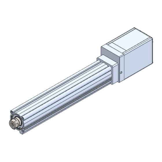
e-Actuator / Rod type
Easy to operate Integrated Controller
Series EQY*H*-****-B*
Motor: Step motor 24 VDC with Battery-less absolute encoder
The intended use of this Electrical Actuator is to convert an electrical
input signal into mechanical motion.
1. Safety Instructions
These safety instructions are intended to prevent hazardous situations
and/or equipment damage. These instructions indicate the level of
potential hazard with the labels of "Caution," "Warning" or "Danger."
They are all important notes for safety and must be followed in addition
*1)
to International Standards (ISO/IEC)
, and other safety regulations.
ISO 4414: Pneumatic fluid power - General rules relating to systems.
ISO 4413: Hydraulic fluid power - General rules relating to systems.
IEC 60204-1: Safety of machinery - Electrical equipment of machines.
(Part 1: General requirements)
ISO 10218-1: Manipulating industrial robots -Safety. Etc.
Refer to the product catalogue, Operation Manual and Handling
Precautions for SMC Products for additional information.
Keep this manual in a safe place for future reference.
Caution indicates a hazard with a low level of risk which, if
Caution
not avoided, could result in minor or moderate injury.
Warning indicates a hazard with a medium level of risk
Warning
which, if not avoided, could result in death or serious injury.
Danger indicates a hazard with a high level of risk which, if
Danger
not avoided, will result in death or serious injury.
Warning
• Always ensure compliance with relevant safety laws and standards.
All work must be carried out in a safe manner by a qualified person in
compliance with applicable national regulations.
• Electromagnetic compatibility
This product is class A equipment intended for use in an industrial
environment. There may be potential difficulties in ensuring
electromagnetic compatibility in other environments due to conducted
as well as radiated disturbances.
2. Specifications
2.1 EQY25 series
Model
Stroke [mm]
Max. work
Horizontal
8
26
*1)
load [kg]
Vertical
2
8
Pushing Force [N]
*2) *3) *4)
36~76
63~122 126~238 232~452
to 300 stroke
30~900
18~700
Speed
[mm/s]
301 to 400 stroke
30~900
18~600
Horizontal
Max. acceleration/
2
deceleration [mm/s
]
Vertical
2
*5)
Pushing speed [mm/s
]
Positioning repeatability [mm]
Lost motion [mm]
*6)
0.1 or less
Screw Lead [mm]
20
12
2
*7)
Impact/Vibration resistance [m/s
]
Ball screw (EQY*DH)
Actuation method
Ball screw + Belt (EQY*H)
Guide type
Sliding bush (piston rod)
Operating temperature [°C]
Operating humidity [% RH]
90 or less (no condensation)
Motor size [mm]
Battery-less absolute
Motor type
(Step motor 24 VDC)
Encoder
Battery-less absolute
(angular displacement sensor)
Power supply voltage [V]
24 VDC ±10%
Max. Power [W]
*8) *9)
*10)
Lock Type
Non magnetizing lock
Holding force [N]
47
78
*1)
*9)
Power consumption [W]
Power supply voltage [V]
24 VDC ±10%
2.2 EQY32 series
Model
Stroke [mm]
Horizontal
30
50
Max. work
*1)
load [kg]
Vertical
3
13
*2) *3) *4)
Pushing Force [N]
50~118
80~189 156~370 296~707
to 300 stroke
36~900
24~800
Speed
301 to 400 stroke
36~900
24~640
[mm/s]
450 to 500 stroke
36~900
24~640
Horizontal
Max. acceleration/
2
deceleration [mm/s
]
Vertical
2
*5)
Pushing speed [mm/s
]
Positioning repeatability [mm]
Lost motion [mm]
*6)
0.1 or less
Screw Lead [mm]
24
16
Impact/Vibration resistance [m/s
2
]
*7)
Ball screw (EQY*DH)
Actuation method
Ball screw + Belt (EQY*H)
Guide type
Sliding bush (piston rod)
Operating temperature [°C]
Operating humidity [% RH]
90 or less (no condensation)
Motor size [mm]
Battery-less absolute
Motor type
(Step motor 24 VDC)
Encoder
Battery-less absolute
(angular displacement sensor)
Power supply voltage [V]
24 VDC ±10%
Max. Power [W]
*8) *9)
*10)
Lock Type
Non magnetizing lock
Holding force [N]
75
108
*9)
Power consumption [W]
Power supply voltage [V]
24 VDC ±10%
2. Specifications (continued)
*1) Horizontal:Use an external guide (external guide friction coefficient: 0.1 or less).
The maximum value of the work load for the positioning operation.
EQY25
The actual transported mass and transport speed will vary depending on the
30 to 400
external guide conditions.
Vertical:Use an external guide (external guide friction coefficient: 0.1 or less)
40
70
when the rod is directed upward or radial load is applied to the rod.
16
30
This is the maximum value of the work load for the positioning operation.
The actual transported mass and transport speed will vary depending on the
9~450
5~225
external guide conditions.
9~300
5~150
Check the speed/acceleration and duty ratio depending on the payload in the
10,000
"Speed vs. payload graph" in the catalogue.
5,000
Set the acceleration/deceleration to horizontal: 10,000 [mm/s
2
5000 [mm/s
] or less.
35
*2) Pushing force accuracy is ±20% (F.S.).
±0.02
*3) The setting range for the "Pushing force" is from 25% to 50% (EQY25*H) and
30% to 70% (EQY32*H).
6
3
The pushing force setting range varies depending on the duty ratio and pushing
50 / 20
speed. Check the "Thrust Conversion Graph" in the catalogue.
*4)Speed and thrust may vary depending on the cable length, load, installation
conditions, etc.
If the cable length exceeds 5 m, the speed/thrust will decrease by up to 10% for
every 5 m. (for 15 m: max. 20% reduction)
5 to 40
*5)"Pushing speed" is the allowable speed for the pushing operation.
When transporting and pushing a workpiece, operate the actuator according to
□
42
the "vertical load capacity" or less.
*6)This is a reference value for correcting errors in reciprocating motion.
*7)Impact resistance: In a drop impact test, no malfunction occurred in the axial
direction and perpendicular direction of the feed screw (at the initial state).
Vibration resistance: 45 to 2000 Hz, 1 sweep, no malfunction in the axial
direction and perpendicular direction of the feed screw (at the initial state).
*8) Power indicates the maximum power during operation including the controller.
86
Use this when selecting the power supply capacity.
*9) For an actuator with lock, add the power consumption for the lock.
157
294
*10)Only applies to actuators supplied with a lock.
5
2.3 Weight [kg]
Series
Stroke
30
50
100
Weight
1.60
1.67
1.84
Lock
Series
Stroke
30
50
100
EQY32
Weight
1.74
1.81
1.98
Lock
30 to 500
90
100
Series
26
46
Stroke
30
50
100
150
Weight
2.55
2.66
2.95
3.23
12~400
6~200
Lock
12~320
6~160
12~320
6~160
Series
10,000
Stroke
30
50
100
150
Weight
2.74
2.85
3.14
3.42
5,000
Lock
35
±0.02
8
4
For special products which include a suffix of "-X#", "-D#", please refer to
50 / 20
the customer drawing of that specific product.
3. Installation
5 to 40
3.1 Installation
□
56.4
• Do not install the product unless the safety instructions have been read
and understood.
• Do not use the product outside of its allowable specification.
• Ensure the product is sized correctly and is suitable for the application.
• Do not operate the product by fixing the piston rod and moving the
109
actuator body.
• Keep the flatness of the mounting surface to within 0.1 mm max.
216
421
Insufficient flatness of a work piece or actuator mounting surface can
5
cause play in the guide and increased sliding resistance. In the case
of overhang mounting (including cantilever), use a support plate or
support guide to avoid deflection of the actuator body.
3. Installation (continued)
• When mounting the actuator, use all mounting holes.
If all mounting holes are not used, this will not maintain the specified
performance. e.g. the amount of displacement of the table will increase.
• When mounting the actuator or workpiece, use screws with adequate
length, but with length less than the maximum thread depth. The use
of screws that are too long can touch the body and cause malfunction.
• Tightening the screws with a torque higher than recommended may
cause malfunction, whilst tightening with a torque lower than
recommended can cause displacement of the mounting position, or
dropping of the work piece.
2
] or less, vertical:
• Avoid using the electric actuator in a way that rotational torque would
be applied to the piston rod. If rotational torque is applied to the piston
rod it will cause deformation, damage and/or reduce the non-rotational
accuracy of the product. The allowable rotational torque is listed below.
• When screwing a bracket or nut onto the threaded portion at the tip of
the piston rod, make sure to retract the piston rod fully, and place a
wrench over the flat portion of the rod that protrudes.
Tighten with consideration to prevent the tightening torque from being
applied to the non-rotating guide.
3.2 Environment
EQY25 (with In-line motor)
150
200
250
300
350
400
• Do not use in an environment where corrosive gases, chemicals, salt
2.10
2.28
2.45
2.63
2.80
2.98
0.31
water or steam are present.
• Do not use in an explosive atmosphere.
EQY25 (with Parallel motor)
150
200
250
300
350
400
• Do not expose to direct sunlight. Use a suitable protective cover.
2.24
2.42
2.59
2.77
2.94
3.12
• Do not install in a location subject to vibration or impact in excess of
0.31
the product's specifications.
• Do not mount in a location exposed to radiant heat that would result in
EQY32 (with In-line motor)
temperatures in excess of the product's specifications.
200
250
300
350
400
450
500
3.63
3.92
4.20
4.49
4.78
5.06
5.35
• Avoid use in the following environments:
0.58
1. Locations where a large amount of dust and cutting chips are
airborne.
EQY32 (with Parallel motor)
2. Locations where the ambient temperature is outside the range of
200
250
300
350
400
450
500
the temperature specification (refer to specifications).
3.82
4.11
4.39
4.68
4.97
5.25
5.54
0.58
3. Locations where the ambient humidity is outside the range of the
humidity specification (refer to specifications).
4. Locations where strong magnetic or electric fields are generated.
Warning
5. Locations where direct vibration or impact is applied to the product.
6. Areas that are dusty, or are exposed to splashes of water and oil
drops.
7. Environments at an altitude of 1000 meters or higher. Heat
dissipation and withstand voltage will decrease. Contact SMC for
details.
• Do not use in an environment where the product is directly exposed to
Warning
liquid, such as cutting oils.
• Install a protective cover when the product is used in an environment
directly exposed to foreign matter such as dust, cutting chips and
spatter.
3.3 Lubrication
• The product has been lubricated for life at manufacture and does not
require lubrication in service. If a lubricant is to be used, contact SMC.
EQY25
EQY32
Allowable Rotational torque
(N·m or less)
1.1
1.4
X
/
\
Warning
Caution
Page 1 of 3
Advertisement

Related Manuals for SMC Networks EQY H B Series


Summary of Contents for SMC Networks EQY H B Series
- Page 1 EQY#-TF222-152EN 2. Specifications 2. Specifications (continued) 3. Installation (continued) ORIGINAL INSTRUCTIONS • When mounting the actuator, use all mounting holes. *1) Horizontal:Use an external guide (external guide friction coefficient: 0.1 or less). 2.1 EQY25 series The maximum value of the work load for the positioning operation. If all mounting holes are not used, this will not maintain the specified Model EQY25...
- Page 2 EQY#-TF222-152EN 3. Installation (continued) 3. Installation (continued) 4. Wiring (continued) 5. How to Order 3.4 Mounting Mounting / Rod side - Head side tapped style Refer to the catalogue on the SMC website. Pin No. Wire colour Name Function Warning (URL: https://www.smcworld.com) for the How to Order information.
- Page 3 EQY#-TF222-152EN 8. Maintenance (continued) 8.3 Appearance Check The following items should be visually checked to ensure that the actuator remains in good condition and there are no concerns; ・Loose Screws, ・Abnormal level of dust or dirt, ・Visual flaws / faults, ・Cable connections, ・Abnormal noises or vibrations.
Need help?
Do you have a question about the EQY H B Series and is the answer not in the manual?
Questions and answers