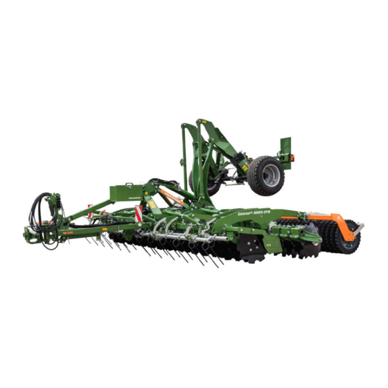
Amazone CatrosXL 4003-2TS Original Operating Manual
Trailed compact disk harrow
Hide thumbs
Also See for CatrosXL 4003-2TS:
- Original operating manual (122 pages) ,
- Operating instructions manual (116 pages) ,
- Original operating manual (122 pages)

Subscribe to Our Youtube Channel
Related Manuals for Amazone CatrosXL 4003-2TS


Summary of Contents for Amazone CatrosXL 4003-2TS
- Page 1 Original operating manual Trailed compact disk harrow Catros 4003-2TS Catros 5003-2TS Catros 6003-2TS SmartLearning www.amazone.de...
- Page 2 Please enter the identification data of the implement. The identification data can be found on the rating plate.
-
Page 3: Table Of Contents
Brake valve for hydraulic brake devices system 6.1.3 Comparing the permissible DC 4.3.3 Brake valve for pneumatic brake value with the actual DC value system Calculating the permissible 4.3.4 Parking brake payload 4.3.5 Wheel chocks MG6828-US-EN-US | A.1 | 02.02.2023 | © AMAZONE... - Page 4 Detaching the safety chain 7.3.3 Adjusting the working depth of the straw harrow 7.3.4 Adjusting the working depth of the side guide plates Adjusting the trailing elements Swinging up the running gear MG6828-US-EN-US | A.1 | 02.02.2023 | © AMAZONE...
- Page 5 Overview of lubrication points 10.3.2 Lubricating wheel hubs 11 Transporting the implement 11.1 Loading the implement 11.1.1 Loading the implement with a crane 11.1.2 Lashing the implement 11.2 Maneuvering implement with hydraulic brake system MG6828-US-EN-US | A.1 | 02.02.2023 | © AMAZONE...
-
Page 7: About This Operating Manual
Indicates a possible danger with moderate risk of severe or fatal physical injury. CAUTION Indicates a danger with low risk of minor or moderate physical injury. 1.1.2 Additional instructions CMS-T-00002416-A.1 IMPORTANT Indicates a risk of implement damage. MG6828-US-EN-US | A.1 | 02.02.2023 | © AMAZONE... -
Page 8: Instructions
CMS-T-005678-B.1 Responses to instructions are indicated by an arrow. Example: 1. Instruction 1 Response to instruction 1 2. Instruction 2 1.1.3.2 Alternative instructions CMS-T-00000110-B.1 Alternative instructions are introduced with the word "or". MG6828-US-EN-US | A.1 | 02.02.2023 | © AMAZONE... -
Page 9: Listings
Example: Point 1 Point 2 1.1.5 Item numbers in illustrations CMS-T-000023-B.1 A framed number in the text, e.g. a 1 , indicates an item number in an adjacent figure. MG6828-US-EN-US | A.1 | 02.02.2023 | © AMAZONE... -
Page 10: Other Applicable Documents
Your suggestions for improvement help us Technische Redaktion provide increasingly user-friendly operating manuals. Postfach 51 Please send us your suggestions by post, fax or D-49202 Hasbergen email. Fax: +49 (0) 5405 501-234 E-Mail: td@amazone.de CMS-I-00000638 MG6828-US-EN-US | A.1 | 02.02.2023 | © AMAZONE... -
Page 11: Safety And Responsibility
2.1.2.1.1 Requirements imposed on all persons who work with the implement CMS-T-00002310-A.1 If the implement is used improperly, people can be injured or killed. To prevent accidents due to improper use, every person who works with MG6828-US-EN-US | A.1 | 02.02.2023 | © AMAZONE... - Page 12 Farmers are categorically familiar with work involving agricultural machines and can instruct agricultural helpers in how to use the machines, if necessary. They can perform specific, simple repairs and maintenance tasks on agricultural machines themselves. MG6828-US-EN-US | A.1 | 02.02.2023 | © AMAZONE...
- Page 13 Objects thrown upward by the tractor or implement can hit and injure persons accompanying the driver. Never allow persons to ride on the implement. Never allow people to climb onto the moving implement. MG6828-US-EN-US | A.1 | 02.02.2023 | © AMAZONE...
- Page 14 Failure to comply with the technical limits values of the implement can cause accidents and serious personal injury or death. Moreover, the implement can be damaged. The technical limit values are provided in the Technical data. Comply with the technical limit values. MG6828-US-EN-US | A.1 | 02.02.2023 | © AMAZONE...
- Page 15 Missing warning symbols increase the risk of serious or fatal injury. Clean dirty warning symbols. Immediately replace any damaged or illegible warning symbols. Affix the intended warning symbols on spare parts. MG6828-US-EN-US | A.1 | 02.02.2023 | © AMAZONE...
-
Page 16: Recognizing And Avoiding Dangers
If people enter the danger area, immediately switch off motors and drives. CMS-I-001131 Before working in the danger area of the implement, secure the tractor and implement. This also applies for quick inspection tasks. MG6828-US-EN-US | A.1 | 02.02.2023 | © AMAZONE... -
Page 17: Safe Operation And Handling Of The Implement
Only couple and transport the implement with suitable tractors. When the implement is coupled on the tractor, ensure that the tractor's connecting device meets the implement requirements. Carefully couple the implement to the tractor. MG6828-US-EN-US | A.1 | 02.02.2023 | © AMAZONE... - Page 18 If the implement is not properly prepared for road travel, it can cause serious traffic accidents. Check the lighting and identification for road travel for proper function. Remove coarse contaminants from the implement. Follow the instructions in the section "Preparing the implement for road travel". MG6828-US-EN-US | A.1 | 02.02.2023 | © AMAZONE...
-
Page 19: Safe Maintenance And Modification
This ensures that the operating permit remains valid in accordance with national and international regulations. Ensure that the specialist workshop only uses conversion parts, spare parts, and special equipment approved by AMAZONE. MG6828-US-EN-US | A.1 | 02.02.2023 | © AMAZONE... - Page 20 Remove the key from the battery circuit breaker. Wait until all parts still in motion after the unit is switched off have come to a stop and until hot parts have cooled down. MG6828-US-EN-US | A.1 | 02.02.2023 | © AMAZONE...
- Page 21 Never position yourself under raised implement parts. If you must perform tasks on or under raised implement parts, lower the implement parts or secure the raised implement parts with a mechanical support or hydraulic locking device. MG6828-US-EN-US | A.1 | 02.02.2023 | © AMAZONE...
- Page 22 CMS-T-00002325-B.1 Special equipment, accessories, and spare parts Special equipment, accessories, and spare parts that do not meet AMAZONE requirements can impair the operational reliability of the implement and cause accidents. Only use original parts or parts that meet the AMAZONE requirements.
-
Page 23: Safety Routines
If there is doubt as to whether the protective devices are properly installed and functional, have the protective devices checked by a qualified specialist workshop. Ensure that the protective devices are properly installed and functional before any activity on the implement. Replace damaged protective devices. MG6828-US-EN-US | A.1 | 02.02.2023 | © AMAZONE... - Page 24 When climbing up and down, never use the control elements as a hand grip. Accidental activation of control elements can unintentionally trigger potentially dangerous functions. When climbing down, never jump off of the implement. MG6828-US-EN-US | A.1 | 02.02.2023 | © AMAZONE...
-
Page 25: Intended Use
Uses other than those specified under the intended use are considered non-intended use. The manufacturer is not liable for any damage resulting from non-intended use; the owner is exclusively liable for such damage. MG6828-US-EN-US | A.1 | 02.02.2023 | © AMAZONE... -
Page 26: Product Description
Lighting to the rear and identification for road travel Trailing elements Roller 10 Side disc Clearer system 11 Left side guide plate 12 Disks 13 Threaded spindle for aligning the disc gangs 14 Leading tool MG6828-US-EN-US | A.1 | 02.02.2023 | © AMAZONE... -
Page 27: Implement With Support Wheels
4.1.2 Implement with support wheels CMS-T-00006303-A.1 CMS-I-00004502 Running gear hydraulic cylinder with vibration Parking brake compensation Wheel chock Support wheel Compressed air tank Central lubrication Brake valve Threaded spindle for aligning the support wheel MG6828-US-EN-US | A.1 | 02.02.2023 | © AMAZONE... -
Page 28: Implement With Greendrill
The following equipment is considered special equipment: GreenDrill pack top seed drill Lighting and identification for road travel Crushboard Cutter roller Pneumatic brake system Spring blade system MG6828-US-EN-US | A.1 | 02.02.2023 | © AMAZONE... -
Page 29: Protective Devices
1 . The ripcord is fastened to the brake valve 3 by means of a spring cotter pin 2 . The brake valve has a hand pump 4 . CMS-I-00003286 MG6828-US-EN-US | A.1 | 02.02.2023 | © AMAZONE... -
Page 30: Brake Valve For Pneumatic Brake System
1 . CMS-I-00004845 4.3.4 Parking brake CMS-T-00004275-A.1 The parking brake prevents the uncoupled implement from rolling. Hand crank CMS-I-00003287 4.3.5 Wheel chocks CMS-T-00004297-B.1 The wheel chocks prevent the uncoupled implement from rolling. CMS-I-00003288 MG6828-US-EN-US | A.1 | 02.02.2023 | © AMAZONE... -
Page 31: Safety Chain
4.4.1 Rear lighting and identification CMS-T-00010504-A.1 Side warning sticker Turn indicators Rear lights and brake lights Triangular warning sign Red warning sticker Yellow warning sticker CMS-I-00007172 4.4.2 Front identification CMS-T-00010503-A.1 Warning sticker CMS-I-00007173 MG6828-US-EN-US | A.1 | 02.02.2023 | © AMAZONE... -
Page 32: Warning Symbols
MO047 MO009 MO007 MO031 MO016 MO001 MO027 MO010 MO014 MO011 MO083 MO011 MO013 MO020 MO010 MO008 MO004 MO002 MO004 MO002 MO009 Mo036 MO039 MO011 MO030 MD047 MD006 MO030 CMS-I-00003528 MO003 MO003 CMS-I-00003482 MG6828-US-EN-US | A.1 | 02.02.2023 | © AMAZONE... -
Page 33: Structure Of The Warning Symbols
Warning symbols indicate danger areas on the implement and warn of residual risks. In these danger areas, there are permanent hazards or hazards that occur unexpectedly. A warning symbol consists of 3 fields: CMS-I-00004316 MG6828-US-EN-US | A.1 | 02.02.2023 | © AMAZONE... -
Page 34: Description Of The Warning Symbols
3-point lifting system. Only operate the tractor’s 3-point lifting system from the designated workstation. CMS-I-00004162 MO003 MOVING SECTION HAZARD Ensure that no one is in the danger area. CMS-I-00004163 MG6828-US-EN-US | A.1 | 02.02.2023 | © AMAZONE... - Page 35 Never ride on the machine. Keep others from climbing onto or riding on the machine. CMS-I-00004168 MO009 ROLLING HAZARD Secure the implement against accidental rolling. Use parking blocks or wheel chocks to secure the implement. CMS-I-00004169 MG6828-US-EN-US | A.1 | 02.02.2023 | © AMAZONE...
- Page 36 This ensures that the implement cannot the machine while the implement components are still tilt and cause crush injuries. folded out, so the implement cannot tip and crush you. MO013 CMS-I-00007174 MG6828-US-EN-US | A.1 | 02.02.2023 | © AMAZONE...
- Page 37 Only attach the lifting equipment at the marked points. CMS-I-00004177 MO020 FALLING HAZARD Do not climb on the finishing roller wheels or finishing roller support. Keep others away from the finishing rollers and finishing roller supports. CMS-I-00004180 MG6828-US-EN-US | A.1 | 02.02.2023 | © AMAZONE...
- Page 38 Loss of implement control can result in death or serious injury. Do not exceed the specified transport speed. CMS-I-00004196 MO039 DETACHMENT HAZARD, Always use the safety chain See the operating manual for details CMS-I-00004199 MG6828-US-EN-US | A.1 | 02.02.2023 | © AMAZONE...
-
Page 39: Rating Plates And Ce Marks
MO083 CMS-I-00007177 4.6 Rating plates and CE marks CMS-T-00004498-G.1 4.6.1 Rating plate on the implement CMS-T-00004505-G.1 Implement number Vehicle ID number Product Permissible technical implement weight Model year Year of manufacture CMS-I-00004294 MG6828-US-EN-US | A.1 | 02.02.2023 | © AMAZONE... -
Page 40: Additional Rating Plate
The figure shows that the stop tap on the hydraulic drawbar is locked in position 1 and open in position ME1677 CMS-I-00003535 4.8 GewindePack CMS-T-00001776-E.1 The GewindePack contains the following: Documents Auxiliary equipment CMS-I-00002306 MG6828-US-EN-US | A.1 | 02.02.2023 | © AMAZONE... -
Page 41: Technical Data
Disc thickness 0.24 in (6 mm) Disk diameter 24.02 in (61 cm) Working depth 1.97-6.3 in (5-16 cm) 5.3 Permissible mounting categories CMS-T-00004236-A.1 Lower link attachment Category 3, Category 4N and Category K700 MG6828-US-EN-US | A.1 | 02.02.2023 | © AMAZONE... -
Page 42: Optimal Working Speed
The workplace-related emission sound pressure level is lower than 70 dB(A), measured in operating status at the ear of the tractor driver with the cab closed. The emission sound pressure level mainly depends on the vehicle used. MG6828-US-EN-US | A.1 | 02.02.2023 | © AMAZONE... -
Page 43: Drivable Slope Inclination
5 | Technical data Drivable slope inclination 5.7 Drivable slope inclination CMS-T-00002297-E.1 Across the slope In direction of travel left In direction of travel right Uphill and downhill Uphill Downhill MG6828-US-EN-US | A.1 | 02.02.2023 | © AMAZONE... -
Page 44: Preparing The Implement
Rear axle load of the operational tractor without mounted lb ( kg) implement or weights lb ( kg) Total weight of front-mounted implement or front weight lb ( kg) Drawbar load MG6828-US-EN-US | A.1 | 02.02.2023 | © AMAZONE... - Page 45 F c T b 0,2 T b Vmin Vmin Vmin CMS-I-00003504 2. Calculate the actual front axle load. × × - × G a b T b F c Vtat Vtat Vtat CMS-I-00005422 MG6828-US-EN-US | A.1 | 02.02.2023 | © AMAZONE...
- Page 46 ( kg) lb ( kg) ≤ ≤ Front axle load lb ( kg) lb ( kg) lb ( kg) ≤ ≤ Rear axle load lb ( kg) lb ( kg) lb ( kg) MG6828-US-EN-US | A.1 | 02.02.2023 | © AMAZONE...
-
Page 47: Determining The Required Coupling Devices
Ø 1.97 in (50 mm) Non-rotatable clevis coupling Pivoting drawbar eye Lower link hitch Lower link crossmember Check whether the coupling device of the tractor is compatible with the coupling device of the implement. MG6828-US-EN-US | A.1 | 02.02.2023 | © AMAZONE... -
Page 48: Comparing The Permissible Dc Value With The Actual Dc Value
Maximum payload = maximum permissible implement weight – tare weight 1. Read off the permissible technical implement weight from the rating plate. To obtain the tare weight, weigh the implement with empty hoppers/tanks. 3. Calculate the payload. MG6828-US-EN-US | A.1 | 02.02.2023 | © AMAZONE... -
Page 49: Coupling The Implement
The pressure accumulator of the emergency brake forces hydraulic oil into the hydraulic lines. 1. Dissipate the hydraulic pressure using the hand CMS-I-00003560 pump on the brake valve of the emergency brake. MG6828-US-EN-US | A.1 | 02.02.2023 | © AMAZONE... -
Page 50: Coupling Hydraulic Hose Lines
Stickers that match the marking are affixed on the implement to illustrate the respective hydraulic functions. The tractor control unit is used in different activation types, depending on the hydraulic function: CMS-I-00000121 MG6828-US-EN-US | A.1 | 02.02.2023 | © AMAZONE... - Page 51 Double-acting concave disks Reduce Increase Working Beige depth of the Double-acting crushboard Reduce Insert Beige Cutter roller Double-acting Lift out Increase Working Beige depth of the Double-acting straw harrow Reduce MG6828-US-EN-US | A.1 | 02.02.2023 | © AMAZONE...
- Page 52 2 . The hydraulic plug connectors lock tangibly. 4. Route the hydraulic hose lines with sufficient freedom of movement and without chafing points. CMS-I-00001045 MG6828-US-EN-US | A.1 | 02.02.2023 | © AMAZONE...
-
Page 53: Coupling The Power Supply
If a different plug connector is used, connect the lines as shown. NOTE 12 V + black - brown CMS-I-00004517 The direction of pump rotation must be the same as shown by the arrow on the tank. MG6828-US-EN-US | A.1 | 02.02.2023 | © AMAZONE... -
Page 54: Disconnecting The Lower Link Hitch
Slightly lift the implement via the lower links. 2. Pull linch pin of the pin. 3. Pull pin. 4. Swing down jack. 5. Insert pin. 6. Secure the pin with a linch pin. CMS-I-00003350 MG6828-US-EN-US | A.1 | 02.02.2023 | © AMAZONE... -
Page 55: Connecting The Ball Hitch Coupling Or Drawbar Eye
"yellow" tractor control unit. 2. Pull linch pin of the pin. 3. Pull pin. 4. Swing down jack. 5. Insert pin. CMS-I-00003552 6. Secure the pin with a linch pin. MG6828-US-EN-US | A.1 | 02.02.2023 | © AMAZONE... -
Page 56: Fastening The Safety Chain
Fasten the safety chain on the tractor as prescribed. CMS-I-00003533 6.3.9 Removing wheel chocks CMS-T-00004296-C.1 1. Remove well chocks from the wheels. 2. Insert wheel chocks in holder. CMS-I-00003546 MG6828-US-EN-US | A.1 | 02.02.2023 | © AMAZONE... -
Page 57: Releasing The Parking Brake
55.12 lb (25 kg). 1. Screw on the holder 1 for the ballast weights with the clamp bracket 2 centered on the rear frame carrier. CMS-I-00000643 MG6828-US-EN-US | A.1 | 02.02.2023 | © AMAZONE... -
Page 58: Adjusting The Scraper To The Roller
1. Unscrew the bolt 1 on the scraper 2 . 2. Move the scraper in the slotted hole. 3. Tighten the bolt 1 . 4. Check the distances with the implement lowered. CMS-I-00000521 MG6828-US-EN-US | A.1 | 02.02.2023 | © AMAZONE... -
Page 59: Adjusting Central Lubrication
1. Adjust the pause times using the blue rotary knob. 2. Adjust the lubricating times using the red rotary knob. 6.4.5 Filling the GreenDrill hopper CMS-T-00006332-B.1 1. Switch off the fan. 2. Switch off control terminal. MG6828-US-EN-US | A.1 | 02.02.2023 | © AMAZONE... - Page 60 Due to the variance in metered material, AMAZONE recommends calibrating the application rate after each filling. CMS-I-00003085 9. Slide up ladder. 10. Lock ladder locking mechanism with lever. 11. Check stop 1 of the ladder locking mechanism. CMS-I-00003067 MG6828-US-EN-US | A.1 | 02.02.2023 | © AMAZONE...
-
Page 61: Preparing The Implement For Road Travel
2. Slide the road safety bars 1 over the tines. 3. Secure the road safety bars with the tensioners 4. Check for firm seat. If the tensioners do not provide enough tension, guide the tensioners through the tine coils. CMS-I-00000517 MG6828-US-EN-US | A.1 | 02.02.2023 | © AMAZONE... -
Page 62: Folding Sections
CMS-I-00006665 1. Drive the tractor and implement on a horizontal surface. To align the implement horizontally in the transport height, activate the tractor lower links and the "yellow" tractor control unit. MG6828-US-EN-US | A.1 | 02.02.2023 | © AMAZONE... -
Page 63: Locking Tractor Control Units
Activate the "yellow" tractor control unit. 6.5.6 Locking tractor control units CMS-T-00006337-C.1 Depending on the equipment, the tractor control units are either locked mechanically or electrically. MG6828-US-EN-US | A.1 | 02.02.2023 | © AMAZONE... -
Page 64: Using The Implement
2. Turn the traffic safety bars 1 180°, place them on top of each other on the holders 2 . 3. Secure the road safety bars with tensioners 3 . CMS-I-00000518 MG6828-US-EN-US | A.1 | 02.02.2023 | © AMAZONE... -
Page 65: Adjusting The Working Depth
4 and the middle of pin 8 . 15. Set the adjustment spindle on the second disc array to the same length. 16. Place hand lever in parking position. 17. Secure hand lever with linch pin. MG6828-US-EN-US | A.1 | 02.02.2023 | © AMAZONE... - Page 66 2. Unscrew both bolts 1 . The bearing journal and the hub of the side disk serve as handles. 3. Turn the side disk up or down in the slotted holes. 4. Tighten bolts. CMS-I-00003202 MG6828-US-EN-US | A.1 | 02.02.2023 | © AMAZONE...
-
Page 67: Hydraulically Adjusting The Working Depth Of The Crushboard
The arrow 1 on the scale 2 shows the set working depth. NOTE The scale value is only for orientation. The scale value does not equal the working depth in centimeters. Hydraulically adjust the working depth via tractor control unit "beige". CMS-I-00002447 MG6828-US-EN-US | A.1 | 02.02.2023 | © AMAZONE... -
Page 68: Adjusting The Working Depth Of The Side Guide Plates
CMS-I-00003484 CMS-I-00003277 IMPORTANT Damage due to the side guide plates being adjusted too low Adjust the side guide plates at a distance of at least 1.18 in (30 mm) from the ground. MG6828-US-EN-US | A.1 | 02.02.2023 | © AMAZONE... -
Page 69: Adjusting The Trailing Elements
3. Take out the linch pins on the left and right adjustment unit. 4. Use the adjustment lever to adjust the trailing elements to the desired height. 5. Secure the trailing elements in the desired position with the linch pins. CMS-I-00002240 MG6828-US-EN-US | A.1 | 02.02.2023 | © AMAZONE... -
Page 70: Swinging Up The Running Gear
The implement is guided horizontally by the support wheels. A spirit level is attached on the implement frame. The spirit level shows the alignment of the implement in the direction of travel. MG6828-US-EN-US | A.1 | 02.02.2023 | © AMAZONE... -
Page 71: Aligning The Implement Horizontally With Lower Link Hitch
1. Drive the tractor and implement on a horizontal surface. 2. Align the implement horizontally using the hydraulic drawbar. MG6828-US-EN-US | A.1 | 02.02.2023 | © AMAZONE... -
Page 72: Using The Cutter Roller
Vibration compensation prevents the implement from swinging, pitching or bouncing in operation. Vibration compensation consists of a stop tap and a hydraulic valve, which are connected to the hydraulic cylinder of the running gear. MG6828-US-EN-US | A.1 | 02.02.2023 | © AMAZONE... -
Page 73: Driving On Headlands
If the implement has trailing elements, turn the implement on the running gear. Use the running gear for road transport or for longer driving on headlands. MG6828-US-EN-US | A.1 | 02.02.2023 | © AMAZONE... -
Page 74: Turning On The Running Gear On The Headlands
If the direction of the implement is the same as the direction of travel, Lower the lower link and activate the "yellow" tractor control unit activate both "yellow" tractor control units and lower the implement. MG6828-US-EN-US | A.1 | 02.02.2023 | © AMAZONE... -
Page 75: Rectifying Faults
Pause times that are too long and Adjust the pause times lubricating times that are too short and lubricating times, see "Adjusting the central lubrication". Grease nipple is clogged see page 70 MG6828-US-EN-US | A.1 | 02.02.2023 | © AMAZONE... - Page 76 CMS-I-00004521 4. Clean faulty lubrication points. 5. Reinstall the grease nipple on the faulty lubrication point. 6. Pump in grease again through the grease nipple MG6828-US-EN-US | A.1 | 02.02.2023 | © AMAZONE...
- Page 77 "9". -MIN- 10. Supply the central lubrication system with power for 12 hours. If grease emerges on the pump after 12 hours, repeat the fault repair procedure. CMS-I-00004520 MG6828-US-EN-US | A.1 | 02.02.2023 | © AMAZONE...
-
Page 78: Parking The Implement
Firmly engage the parking brake with the hand crank. CMS-I-00003352 9.2 Placing the wheel chocks CMS-T-00004316-B.1 1. Take wheel chocks out of the holder. 2. Place wheel chocks under the wheels. CMS-I-00003547 MG6828-US-EN-US | A.1 | 02.02.2023 | © AMAZONE... -
Page 79: Uncoupling The Lower Link Hitch
1. Offload the tractor's lower links 1 . 2. Release the lower link catch hook 2 . 3. From the tractor seat, uncouple the tractor lower links from the implement. 4. Drive the tractor forward. CMS-I-00003346 MG6828-US-EN-US | A.1 | 02.02.2023 | © AMAZONE... -
Page 80: Disconnecting The Ball Hitch Coupling Or Drawbar Eye
1. Open the stop tap on the hydraulic drawbar. 2. Use the "yellow" tractor control unit to offload the drawbar eye. 3. Uncouple the drawbar eye from the clevis coupling of the tractor. CMS-I-00003557 MG6828-US-EN-US | A.1 | 02.02.2023 | © AMAZONE... -
Page 81: Uncoupling The Ball Hitch Coupling
"yellow" tractor control unit. CMS-I-00003558 9.5 Uncoupling the power supply CMS-T-00001402-G.1 1. Unplug the connector 1 for the power supply. CMS-I-00001048 2. Hook-in the connector 1 on the hose cabinet. CMS-I-00001248 MG6828-US-EN-US | A.1 | 02.02.2023 | © AMAZONE... -
Page 82: Uncoupling The Hydraulic Hose Lines
3. Disconnect the yellow coupling head of the brake line 1 from the tractor. 4. Disconnect the yellow coupling head to the empty coupling on the implement. CMS-I-00003559 5. Close the caps of the tractor coupling heads. MG6828-US-EN-US | A.1 | 02.02.2023 | © AMAZONE... -
Page 83: Disconnecting The Hydraulic Brake System
1. Disconnect the ripcord of the emergency brake from the tractor. 2. Disconnect the hydraulic plug connector from the hydraulic socket. CMS-I-00003560 9.8 Detaching the safety chain CMS-T-00004315-B.1 Detach the safety chain from the tractor. CMS-I-00003554 MG6828-US-EN-US | A.1 | 02.02.2023 | © AMAZONE... -
Page 84: Attaching Safeguard Against Unauthorized Use
9 | Parking the implement Attaching safeguard against unauthorized use 9.9 Attaching safeguard against unauthorized use CMS-T-00005090-B.1 1. Attach safeguard against unauthorized use on the hitch device. 2. Attach padlock. CMS-I-00003534 MG6828-US-EN-US | A.1 | 02.02.2023 | © AMAZONE... -
Page 85: Maintaining The Implement
Checking the ball hitch coupling see page 89 Checking the drawbar eye see page 89 Every 50 operating hours / weekly Checking the hydraulic hose lines see page 83 Checking the wheels see page 83 MG6828-US-EN-US | A.1 | 02.02.2023 | © AMAZONE... -
Page 86: Replacing The Disks
1. Slightly lift the implement. CMS-I-00002450 2. Unscrew the 4 bolts 1 of the disk fastening. 3. Take off the disk 2 . 4. Fasten the new disk with the 4 bolts. MG6828-US-EN-US | A.1 | 02.02.2023 | © AMAZONE... -
Page 87: Checking The Disk Carrier Connection
The disks are not standing on the ground. 3. Unscrew the lock nuts 1 on all of the adjustment spindles. CMS-I-00003204 4. Align the disk gangs using the hexagonal profile 2 on the adjustment spindle. MG6828-US-EN-US | A.1 | 02.02.2023 | © AMAZONE... -
Page 88: Checking The Rollers
10.1.6 Checking lower link pins CMS-T-00004233-B.1 INTERVAL Every 500 operating hours Every 6 months 1. Check lower link pins for cracks or worn areas. 2. Replace the pins if there is significant wear. MG6828-US-EN-US | A.1 | 02.02.2023 | © AMAZONE... -
Page 89: Checking The Hydraulic Hose Lines
M20 x 1.5 258.15 ft-lb (350 Nm) (-0/+30) wheel M22 x 1.5 331.9 ft-lb (450 Nm) (-0/+60) 1. Check the tire pressure as specified on the stickers. 2. Check the bolted connection. MG6828-US-EN-US | A.1 | 02.02.2023 | © AMAZONE... -
Page 90: Checking The Hub Bearing
5. Checking the bearing clearance of the wheel hubs with levers. If the wheel hub bearing has play, have the wheel hub bearing adjusted by a specialist workshop. CMS-I-00003598 MG6828-US-EN-US | A.1 | 02.02.2023 | © AMAZONE... -
Page 91: Checking The Brake Pads
0 psi (0 bar) when the brake is not activated 1. Check the compressed air lines and bellows for damage. 2. Have damaged components replaced by a specialist workshop. 3. Have the specified test criteria checked by a specialist workshop. MG6828-US-EN-US | A.1 | 02.02.2023 | © AMAZONE... -
Page 92: Dewatering The Compressed Air Tank
If the tensioning straps are loose, tension the tensioning straps with nuts. If the tensioning straps are damaged or cannot be tensioned, have the tensioning straps replaced in a specialist workshop. MG6828-US-EN-US | A.1 | 02.02.2023 | © AMAZONE... -
Page 93: Cleaning The Compressed Air Line Filter
7. Grease the sealing surfaces, seal ring, and compressed air line filter. CMS-I-00003573 8. Check the position of the seal ring. 9. Reassemble in the reverse sequence. CMS-I-00003572 MG6828-US-EN-US | A.1 | 02.02.2023 | © AMAZONE... -
Page 94: Checking The Axle Bolts
M20 8.8 (420 Nm) 1. Check the lower link hitch for damage, deformation, cracks and wear. 2. Have the damaged lower link hitch replaced by a specialist workshop. 3. Check bolt tightening torques. MG6828-US-EN-US | A.1 | 02.02.2023 | © AMAZONE... -
Page 95: Checking The Ball Hitch Coupling
2.03 in (51.5 mm) M16 10.9 (300 Nm) 413.03 ft-lb D50 (LI059) 2.03 in (51.5 mm) M20 10.9 (560 Nm) D50 (LI011) 2.03 in (51.5 mm) M20 8.8 302.4 ft-lb (410 Nm) MG6828-US-EN-US | A.1 | 02.02.2023 | © AMAZONE... -
Page 96: Check The Central Lubrication System
If the fill level is low in the tank fill in grease through the filling nipple 3 until just -MAX- below the "MAX" mark. If grease emerged on the pressure relief valve -MIN- see "Rectifying faults". CMS-I-00004515 MG6828-US-EN-US | A.1 | 02.02.2023 | © AMAZONE... -
Page 97: Cleaning The Implement
11.81 in (30 cm) between the high- pressure nozzle and the implement. Do not exceed maximum water pressure of 1,740.45 psi (120 bar). Clean the implement with a high-pressure cleaner or a hot water high-pressure cleaner. MG6828-US-EN-US | A.1 | 02.02.2023 | © AMAZONE... -
Page 98: Lubricating The Implement
Only lubricate the implement with the lubricants listed in the technical data. CMS-I-00002270 Press all the spent grease completely out of the bearings. MG6828-US-EN-US | A.1 | 02.02.2023 | © AMAZONE... -
Page 99: Overview Of Lubrication Points
10 | Maintaining the implement Lubricating the implement 10.3.1 Overview of lubrication points CMS-T-00004969-B.1 CMS-I-00003571 Every 50 operating hours CMS-I-00003569 CMS-I-00002245 MG6828-US-EN-US | A.1 | 02.02.2023 | © AMAZONE... - Page 100 10 | Maintaining the implement Lubricating the implement CMS-I-00003568 CMS-I-00003567 CMS-I-00003563 CMS-I-00003565 CMS-I-00003566 CMS-I-00003564 Every 200 operating hours CMS-I-00004519 MG6828-US-EN-US | A.1 | 02.02.2023 | © AMAZONE...
-
Page 101: Lubricating Wheel Hubs
10.3.2 Lubricating wheel hubs CMS-T-00004970-B.1 INTERVAL Every 500 operating hours 1. Remove wheel hub cap from wheel hub. 2. Top up the wheel hub cap with grease. 3. Fit wheel hub cap on wheel hub. MG6828-US-EN-US | A.1 | 02.02.2023 | © AMAZONE... -
Page 102: Transporting The Implement
11 | Transporting the implement Transporting the implement CMS-T-00004524-E.1 11.1 Loading the implement CMS-T-00004262-D.1 11.1.1 Loading the implement with a crane CMS-T-00004263-D.1 The implement has 6 attachment points for lifting slings. CMS-I-00003576 MG6828-US-EN-US | A.1 | 02.02.2023 | © AMAZONE... -
Page 103: Lashing The Implement
4,409.25 lb (2,000 kg) 1. Attach the slings for lifting on the intended attachment points. 2. Slowly lift the implement. 11.1.2 Lashing the implement CMS-T-00010508-A.1 The implement has 4 lashing points for lashing straps. MG6828-US-EN-US | A.1 | 02.02.2023 | © AMAZONE... -
Page 104: Maneuvering Implement With Hydraulic Brake System
3. Lash the implement in compliance with national regulations for securing loads. 11.2 Maneuvering implement with hydraulic brake system CMS-T-00005208-B.1 If the implement's hydraulic brake system is uncoupled, the implement is braked. MG6828-US-EN-US | A.1 | 02.02.2023 | © AMAZONE... -
Page 105: Maneuvering The Implement With Pneumatic Brake System
WARNING Risk of accident due to unbraked implement To maneuver the implement, connect the implement to a suitable tractor using the coupling device. Only maneuver the implement at walking speed. MG6828-US-EN-US | A.1 | 02.02.2023 | © AMAZONE... - Page 106 NOTE To brake the implement again, there must be sufficient compressed air in the compressed air tank. If there is not enough compressed air, connect the pneumatic brake system to a tractor. MG6828-US-EN-US | A.1 | 02.02.2023 | © AMAZONE...
-
Page 107: Appendix
(210 Nm) (250 Nm) 154.89 ft-lb 221.27 ft-lb 261.83 ft-lb (210 Nm) (300 Nm) (355 Nm) 0.94 in (24 mm) 165.95 ft-lb 232.33 ft-lb 280.27 ft-lb M16x1.5 (225 Nm) (315 Nm) (380 Nm) MG6828-US-EN-US | A.1 | 02.02.2023 | © AMAZONE... - Page 108 6.2 ft-lb (8.4 Nm) 178.49 ft-lb (242 Nm) 15.05 ft-lb (20.4 Nm) 252.25 ft-lb (342 Nm) 30.02 ft-lb (40.7 Nm) 346.65 ft-lb (470 Nm) 52 ft-lb (70.5 Nm) 434.42 ft-lb (589 Nm) MG6828-US-EN-US | A.1 | 02.02.2023 | © AMAZONE...
-
Page 109: Other Applicable Documents
12 | Appendix Other applicable documents 12.2 Other applicable documents CMS-T-00004229-A.1 Tractor operating manual Operating Manual ‒ GreenDrill GD 501 MG6828-US-EN-US | A.1 | 02.02.2023 | © AMAZONE... -
Page 110: Directories
Tractor In this operating manual, the designation tractor is always used, even for other agricultural towing machines. Implements are mounted on the tractor or towed by the tractor. MG6828-US-EN-US | A.1 | 02.02.2023 | © AMAZONE... -
Page 111: Index
Capacity characteristics of the tractor Front ballasting calculating Central lubrication adjusting Front lighting cleaning Implement Clearer system GewindePack adjusting Description Position Compressed air line filter cleaning Compressed air tank Harrow system checking adjusting dewatering MG6828-US-EN-US | A.1 | 02.02.2023 | © AMAZONE... - Page 112 Rear harrow calculating See Adjusting the trailing elements Lower link hitch Rear lighting checking Release valve 24, 99 connecting disconnecting Road safety bars attaching Lower link pin Description checking removing Maintenance 79, 79 MG6828-US-EN-US | A.1 | 02.02.2023 | © AMAZONE...
- Page 113 Warning symbols Description Stop tap on the hydraulic drawbar Positions Functions Structure Straw harrow Wheel chocks Adjusting the aggressiveness Description Hydraulic working depth adjustment placing removing Wheel hubs lubricating Wheels checking MG6828-US-EN-US | A.1 | 02.02.2023 | © AMAZONE...
- Page 114 Adjusting the side guide plates Adjusting the spring blade system Adjusting the spring clearer system Adjusting the trailing elements Hydraulic adjustment Hydraulic crushboard adjustment Hydraulic straw harrow adjustment Manual disk adjustment Working speed MG6828-US-EN-US | A.1 | 02.02.2023 | © AMAZONE...
- Page 116 AMAZONEN-WERKE H. DREYER SE & Co. KG Postfach 51 49202 Hasbergen-Gaste Germany +49 (0) 5405 501-0 amazone@amazone.de www.amazone.de MG6828-US-EN-US | A.1 | 02.02.2023 | © AMAZONE...
Need help?
Do you have a question about the CatrosXL 4003-2TS and is the answer not in the manual?
Questions and answers