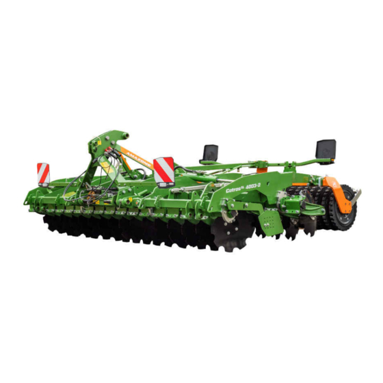
Amazone CatrosXL 4003-2 Original Operating Manual
Mounted compact disc harrow
Hide thumbs
Also See for CatrosXL 4003-2:
- Operating instructions manual (82 pages) ,
- Original operating manual (88 pages) ,
- Translation of the original operating instructions (88 pages)

Subscribe to Our Youtube Channel
Related Manuals for Amazone CatrosXL 4003-2


Summary of Contents for Amazone CatrosXL 4003-2
- Page 1 Original operating manual Mounted compact disc harrow Catros 4003-2 Catros 5003-2 Catros 6003-2 SmartLearning www.amazone.de...
- Page 2 Please enter the identification data of the implement. The identification data can be found on the rating plate.
-
Page 3: Table Of Contents
TABLE OF CONTENTS TABLE OF CONTENTS Threaded cartridge 1 About this operating manual Diagrams 5 Technical data 1.1.1 Warnings and signal words 1.1.2 Further instructions Dimensions 1.1.3 Instructions Soil tillage tools 1.1.4 Lists Permitted mounting categories 1.1.5 Item numbers in figures Optimal working speed Other applicable documents Performance characteristics of... - Page 4 TABLE OF CONTENTS 6.4.4 Adjusting the scraper to the roller 10.2.1 Overview of lubrication points 6.4.5 Removing the road safety bars 10.3 Cleaning the implement 6.4.6 Adjusting the trailing elements 6.4.7 Installing ballast weights 11 Loading the implement 6.4.8 Adjusting the central lubrication 11.1 Loading the implement with a Preparing the machine for road...
-
Page 5: About This Operating Manual
1 | About this operating manual About this operating manual CMS-T-00000081-D.1 1.1 Diagrams CMS-T-005676-C.1 1.1.1 Warnings and signal words CMS-T-00002415-A.1 Warnings are marked with a vertical bar with a triangular safety symbol and the signal word. The signal words "DANGER", "WARNING" or "CAUTION" describe the severity of the potential danger and have the following meanings: DANGER... -
Page 6: Instructions
1 | About this operating manual Diagrams ENVIRONMENTAL INFORMATION Indicates a risk for environmental damage. NOTE Indicates application tips and instructions for optimal use. 1.1.3 Instructions CMS-T-00000473-B.1 Numbered instructions CMS-T-005217-B.1 Actions that have to be performed in a specific sequence are represented as numbered instructions. The specified sequence of the actions must be observed. -
Page 7: Lists
1 | About this operating manual Diagrams Example: 1. Instruction 1 Alternative instruction 2. Instruction 2 Instructions with only one action CMS-T-005211-C.1 Instructions with only one action are not numbered, but rather shown with a arrow. Example: Instruction Instructions without sequence CMS-T-005214-C.1 Instructions that do not require a specific sequence are shown as a list with arrows. -
Page 8: Other Applicable Documents
Your suggestions for improvement help us Technische Redaktion to create ever more user-friendly operating manuals. Postfach 51 Please send us your suggestions by post, fax or D-49202 Hasbergen email. Fax: +49 (0) 5405 501-234 E-Mail: td@amazone.de MG6829-EN-II | H.1 | 10.02.2022... -
Page 9: Safety And Responsibility
2 | Safety and responsibility Safety and responsibility CMS-T-00002298-K.1 2.1 Basic safety instructions CMS-T-00002301-K.1 2.1.1 Meaning of the operating manual CMS-T-00006180-A.1 Observe the operating manual The operating manual is an important document and a part of the implement. It is intended for the user and contains safety-related information. - Page 10 2 | Safety and responsibility Basic safety instructions the machine must meet the following minimum requirements: The person is physically and mentally capable of controlling the machine. The person can safely perform work with the machine within the scope of this operating manual.
- Page 11 2 | Safety and responsibility Basic safety instructions Farmers can be e.g.: Farmers with higher education or training from a technical college Farmers by experience (e.g. inherited farm, comprehensive practical knowledge) Contractors who work by order of farmers Activity example: Safety training for agricultural helpers 2.1.2.1.4 Agricultural helpers CMS-T-00002313-A.1...
- Page 12 2 | Safety and responsibility Basic safety instructions 2.1.2.3 Danger for children CMS-T-00002308-A.1 Danger for children Children cannot assess dangerous situations and can behave unpredictably. As a result, children are at a higher risk. Keep children away. When you drive out or actuate machine movements, make sure that there are no children in the danger area.
- Page 13 2 | Safety and responsibility Basic safety instructions 2.1.2.4.2 Personal protective equipment CMS-T-00002316-B.1 Personal protective equipment Wearing personal protective equipment is an important safety element. Missing or unsuitable personal protective equipment increases the risk of damage to health and personal injury. Personal protective equipment includes: work gloves, safety shoes, protective clothing, breathing protection, hearing protection, face protection, and eye protection Determine the personal protective equipment required for each job and have it ready.
-
Page 14: Knowing And Preventing Dangers
2 | Safety and responsibility Basic safety instructions 2.1.3 Knowing and preventing dangers CMS-T-00002303-D.1 2.1.3.1 Safety hazards on the machine CMS-T-00002318-D.1 Liquids under pressure Escaping high pressure hydraulic fluid can penetrate into the body through the skin and cause serious personal injuries. -
Page 15: Safe Operation And Handling Of The Machine
2 | Safety and responsibility Basic safety instructions 2.1.3.2 Danger areas CMS-T-00002319-C.1 Dangers areas on the machine The following basic dangers are encountered in the danger areas: The implement and its work tools move during operation. Hydraulically raised machine parts can descend unnoticed and slowly. - Page 16 2 | Safety and responsibility Basic safety instructions 2.1.4.2 Driving safety CMS-T-00002321-D.1 Risk when driving on roads and fields Any mounted or towed implement as well as front or rear ballast weights on the tractor influence the driving behaviour and the steering and braking power of the tractor. The driving characteristics also depend on the operating condition, the fill level of the load, and on the ground.
-
Page 17: Safe Maintenance And Modification
Have any design changes and extensions performed only by a qualified specialist workshop. To ensure that the operating permit remains valid in accordance with national and international regulations, ensure that the specialist workshop only uses conversion parts, spare parts and special equipment approved by AMAZONE. MG6829-EN-II | H.1 | 10.02.2022... - Page 18 2 | Safety and responsibility Basic safety instructions 2.1.5.2 Work on the machine CMS-T-00002323-C.1 Only work on the machine when it is at a standstill If the machine is not standing still, part can move unintentionally or the machine can be set in motion. This can result in serious injury or death.
- Page 19 2 | Safety and responsibility Basic safety instructions Maintenance work Improper maintenance work, particularly on safety-related components, endangers operational safety. This can result in accidents and serious personal injury or even death. Safety-related components include, for example, hydraulic components, electronic components, frames, springs, trailer coupling, axles and axle suspensions, lines and tanks containing flammable substances.
- Page 20 CMS-T-00002325-B.1 Special equipment, accessories, and spare parts Special equipment, accessories, and spare parts that do not meet AMAZONE requirements can impede the operational safety of the implement and cause accidents. Only use original parts or parts that meet AMAZONE requirements.
-
Page 21: Safety Routines
2 | Safety and responsibility Safety routines 2.2 Safety routines CMS-T-00002300-C.1 Securing the tractor and implement If the tractor and implement are not secured against unintentional starting and rolling away, the tractor and implement can be set in motion in an uncontrolled manner, and can run over, crush and kill people. Lower the raised implement or raised implement parts. - Page 22 2 | Safety and responsibility Safety routines Climbing on and off Negligent behaviour while climbing on and off can cause people to fall off the ladder. People who climb onto the machine without using the intended access steps can slip, fall, and suffer severe injury. Use only the intended access steps Dirt as well operating materials can impede walking safety and stability.
-
Page 23: Intended Use
Further instructions for intended use in special cases can be requested from AMAZONE. Uses other than those specified under the intended use are considered as improper. The manufacturer is not liable for any damage resulting from improper use, solely the operator is responsible. -
Page 24: Product Description
4 | Product description Product description CMS-T-00004382-F.1 4.1 Implement overview CMS-T-00004410-C.1 CMS-I-00003203 MG6829-EN-II | H.1 | 10.02.2022... -
Page 25: Function Of The Implement
4 | Product description Function of the implement Working depth adjustment 10 Left side guide plate Right side guide plate 11 Discs Rating plate and embossed identification 12 Threaded spindle for aligning the disc gangs number 13 Threaded cartridge Working depth indicator for the discs 14 Central lubrication Lighting and identification for road travel towards 15 Spirit level... -
Page 26: Protective Equipment
4 | Product description Protective equipment 4.4 Protective equipment CMS-T-00000611-D.1 4.4.1 Road safety bars CMS-T-00000612-D.1 To protect from injuries during road transport, the road safety bar covers the tines on the rear harrow. CMS-I-00000088 4.5 Warning symbols CMS-T-00004388-D.1 4.5.1 Positions of the warning symbols CMS-T-00004389-B.1 MD100 MD100... -
Page 27: Layout Of The Warning Symbols
4 | Product description Warning symbols MD084 MD084 CMS-I-00003482 4.5.2 Layout of the warning symbols CMS-T-000141-D.1 Warning symbols indicate danger areas on the machine and warn against residual dangers. In these danger areas, there are permanent or unexpected dangers. A warning symbol consists of two fields: Field 1 shows the following: A pictogram depicting the danger area, CMS-I-00000416... - Page 28 4 | Product description Warning symbols MD 084 Risk of crushing for the whole body from lowering implement parts Make sure that there is nobody standing in the danger area. CMS-I-000454 MD 096 Risk of infection from escaping hydraulic fluid under high pressure Never look for leaks in hydraulic hose lines using your hand or fingers.
-
Page 29: Rating Plate On The Implement
4 | Product description Rating plate on the implement MD 199 Risk of accident if the hydraulic system pressure is too high Only couple the implement to tractors with a maximum tractor hydraulic pressure of 210 bar. CMS-I-00000486 MD 217 Danger due to the implement tipping over Never park the implement in transport position. -
Page 30: Front Lighting And Identification
4 | Product description Front lighting and identification 4.7 Front lighting and identification CMS-T-000187-G.1 Warning sign Marker light CMS-I-00004701 NOTE The lighting and identification for road travel can vary depending on the national regulations. 4.8 Threaded cartridge CMS-T-00001776-C.1 The threaded cartridge contains the following items: Documents Aids CMS-I-00002306... -
Page 31: Technical Data
5 | Technical data Technical data CMS-T-00004392-E.1 5.1 Dimensions CMS-T-00004396-B.1 Catros 4003-2 5003-2 6003-2 Transport width 2.95 m Transport height 2.7 m 3.2 m 3.7 m Total length 6.88 m Working width Centre of gravity distance 1.38 m 5.2 Soil tillage tools CMS-T-00004395-C.1 Catros 4003-2... -
Page 32: Performance Characteristics Of The Tractor
5 | Technical data Performance characteristics of the tractor 5.5 Performance characteristics of the tractor CMS-T-00004393-A.1 Catros 4003-2 5003-2 6003-2 Starting at 118 kW / 160 Starting at 147 kW / 200 Starting at 176 kW / 240 Engine rating Electrical system Battery voltage 12 V... - Page 33 5 | Technical data Drivable slope inclination Up the slope and down the slope Up the slope 15 % Down the slope 15 % MG6829-EN-II | H.1 | 10.02.2022...
-
Page 34: Preparing The Machine
6 | Preparing the machine Preparing the machine CMS-T-00004397-F.1 6.1 Calculating the required tractor characteristics CMS-T-00000063-D.1 CMS-I-00000581 Calculated Designation Unit Description values Tractor empty weight Front axle load of the operational tractor without mounted implement or ballast weights Rear axle load of the operational tractor without mounted implement or ballast weights Total weight of front-mounted implement or front ballast Permissible total weight of rear-mounted implement or rear... - Page 35 6 | Preparing the machine Calculating the required tractor characteristics Calculated Designation Unit Description values Distance between the centre of the front axle and the centre of the lower link connection Centre of gravity distance: Distance between the centre of gravity of the front-mounted implement or the front ballast and the centre of the lower link connection Wheelbase...
- Page 36 6 | Preparing the machine Calculating the required tractor characteristics 3. Calculate the actual total weight of the tractor- implement combination. CMS-I-00000515 4. Calculate the actual rear axle load. Htat Vtat Htat Htat CMS-I-00000514 5. Determine the tyre load capacity for two tractor tyres in the manufacturer specifications.
-
Page 37: Adjusting The 3-Point Mounting Frame
6 | Preparing the machine Adjusting the 3-point mounting frame 6.2 Adjusting the 3-point mounting frame CMS-T-00004764-B.1 6.2.1 Adjusting the 3-point mounting frame for mounting category 3 CMS-T-00004424-B.1 Mounting category 3 Mounting category 4 32 mm 36.6 mm 50.8 mm 1. -
Page 38: Adjusting The 3-Point Mounting Frame For Mounting Category
6 | Preparing the machine Adjusting the 3-point mounting frame 6.2.2 Adjusting the 3-point mounting frame for mounting category 4 CMS-T-00004423-B.1 Mounting category 3 Mounting category 4 32 mm 45.2 mm 36.6 mm 50.8 mm 1. Install the ball sleeve with the top link pin 1 . 2. -
Page 39: Coupling The Implement
6 | Preparing the machine Coupling the implement 6.3 Coupling the implement CMS-T-00004400-F.1 6.3.1 Driving the tractor towards the implement CMS-T-00005794-C.1 Enough space must remain between the tractor and implement so that the supply lines can be coupled without obstructions. Drive the tractor towards the implement, leaving a sufficient distance. - Page 40 6 | Preparing the machine Coupling the implement Designation Function Tractor control unit Fold Blue Section Double-acting Unfold Increase Working Green depth of the Double-acting concave discs Reduce WARNING Risk of injury or even death If the hydraulic hose lines are incorrectly connected, the hydraulic functions may be faulty.
-
Page 41: Coupling The Power Supply
6 | Preparing the machine Coupling the implement 3. Couple the hydraulic hose lines 1 to the hydraulic sockets of the tractor according to the marking 2 . The hydraulic plugs lock perceptibly. 4. Route the hydraulic hose lines with sufficient freedom of movement and without chafing points. -
Page 42: Coupling The 3-Point Mounting Frame
6 | Preparing the machine Coupling the implement 6.3.5 Coupling the 3-point mounting frame CMS-T-00001400-F.1 1. Set the tractor lower links 1 to the same height. 2. Couple the lower links 1 from the tractor seat. 3. Couple the top link 2 . 4. -
Page 43: Preparing The Implement For Operation
6 | Preparing the machine Preparing the implement for operation If a different plug is used, connected the lines as shown. NOTE 12 V + Black - Brown CMS-I-00004517 The direction of rotation of the pump must match with the arrow on the tank. 6.4 Preparing the implement for operation CMS-T-00004401-E.1 6.4.1 Unfolding the sections... - Page 44 6 | Preparing the machine Preparing the implement for operation Adjustment spindle Working depth shorten increase lengthen reduce 8. Set the adjustment spindle to the desired length using the hand lever. 9. Set the locking pin 2 vertically. 10. Swivel up the safety clip. 11.
-
Page 45: Adjust The Working Depth Of The Side Guide Plates
6 | Preparing the machine Preparing the implement for operation The arrow 1 on the scale 2 shows the set working depth. NOTE The scale value only serves for orientation. The scale value does not represent the working depth in centimetres. 3. -
Page 46: Adjusting The Scraper To The Roller
6 | Preparing the machine Preparing the implement for operation CMS-I-00003277 IMPORTANT Damage due to the side guide plates being set too deep Set the side guide plates at a distance of at least 30 mm from the ground. 1. Slightly raise the implement. 2. -
Page 47: Removing The Road Safety Bars
6 | Preparing the machine Preparing the implement for operation 1. Loosen the bolt 1 on the scraper 2 . 2. Move the scraper in the elongated slot. 3. Tighten the bolt 1 . 4. Check the distances when the implement is lowered. -
Page 48: Installing Ballast Weights
6 | Preparing the machine Preparing the implement for operation 2. Use the setting lever 1 to relieve the linch pins 2 and 3 . 3. Remove the linch pins on the left and right adjustment unit. 4. Using the setting lever, adjust the trailing elements to the desired height. -
Page 49: Adjusting The Central Lubrication
6 | Preparing the machine Preparing the implement for operation 1. Screw on the bracket 1 for the ballast weights with the clamp 2 at the centre of the rear frame carrier. CMS-I-00000643 2. Put two ballast weights 1 on each bracket. 3. -
Page 50: Preparing The Machine For Road
6 | Preparing the machine Preparing the machine for road travel NOTE The rotary knob position "0" is only intended for -MAX- manufacturer purposes. Recommended lubrication time: -MIN- 8 minutes Recommended pause times when applying slurry: Initial operation: 1 hour Later: 1-2 hours Recommended pause times without slurry: ensure 3 lubrication times per day of operation... -
Page 51: Folding The Sections
6 | Preparing the machine Calculating the permissible payload 6.5.2 Folding the sections CMS-T-00004551-C.1 1. Set the working depth of the discs to the minimum. 2. Completely lift the implement with the lower link or the hydraulic drawbar. 3. Actuate the "blue" tractor control unit. The sections fold. -
Page 52: Using The Machine
7 | Using the machine Using the machine CMS-T-00007021-C.1 7.1 Using the implement CMS-T-001727-F.1 1. Lower the implement on the field. 2. Move the hydraulic system of the 3-point power lift into float position. 7.2 Turning on the headlands CMS-T-001728-B.1 To prevent lateral loads when driving in curves on the headlands, raise the soil tillage tools. -
Page 53: Eliminating Faults
8 | Eliminating faults Eliminating faults CMS-T-00007934-A.1 Errors Cause Solution The working depth is uneven The hydraulic cylinders have see page 50 across the entire implement width different lengths Grease emerging on the pump for Incorrect power supply to the Ensure power supply of 9.6 V –... - Page 54 8 | Eliminating faults Different working depths across the working width CMS-T-00005120-A.1 1. completely extend the hydraulic cylinders with the "green" tractor control unit. 2. Hold the "green" tractor control unit for 10 seconds. The hydraulic cylinders will be synchronised. Grease emerging on the pump for the central lubrication CMS-T-00006312-A.1 Depending on the equipment, the central lubrication...
- Page 55 8 | Eliminating faults When all of the faulty lubrication points have been cleaned, the central lubrication system can be tested over a longer period of time as follows: -MAX- 9. Set the blue rotary knob on the pump at "3" and the red rotary knob at "9".
-
Page 56: Parking The Machine
9 | Parking the machine Parking the machine CMS-T-00004407-D.1 9.1 Unfolding the sections CMS-T-00004426-C.1 1. Completely raise the implement. 2. Pull on the pull rope for the hydraulic unfolding safety mechanism and actuate the "blue" tractor control unit. The sections unfold. 3. -
Page 57: Driving The Tractor Away From The Implement
9 | Parking the machine Driving the tractor away from the implement 5. Uncouple the lower links 2 from the implement from the tractor seat. 6. Drive the tractor forward. 9.3 Driving the tractor away from the implement CMS-T-00005795-C.1 There must be enough space between the tractor and implement so that the supply lines can be uncoupled without obstructions. -
Page 58: Disconnecting The Hydraulic Hose Lines
9 | Parking the machine Disconnecting the hydraulic hose lines 9.5 Disconnecting the hydraulic hose lines CMS-T-00000277-E.1 1. Secure the tractor and implement. 2. Put the control lever on the tractor control unit in float position. 3. Disconnect the hydraulic hose lines 1 . 4. -
Page 59: Repairing The Machine
10 | Repairing the machine Repairing the machine CMS-T-00004554-D.1 10.1 Maintaining the machine CMS-T-00004785-D.1 10.1.1 Maintenance schedule After initial operation Checking the disc carrier connection see page 56 Checking the rollers see page 57 Checking the hydraulic hose lines see page 57 as required Replacing the discs see page 56... -
Page 60: Replacing The Discs
10 | Repairing the machine Maintaining the machine 10.1.2 Replacing the discs CMS-T-00002327-E.1 INTERVAL as required Original disc diameter Wear limit 46 cm 36 cm 48 cm 40 cm 61 cm 43 cm 66 cm 46 cm 1. Slightly raise the implement. 2. -
Page 61: Checking The Rollers
10 | Repairing the machine Maintaining the machine 10.1.4 Checking the rollers CMS-T-00002329-C.1 INTERVAL After initial operation Every 200 operating hours Every 3 months Check the bolts 1 for tightness. If the bolts need to be replaced, pay attention to the alignment of the bolts. Check the roller bearing 2 for ease of movement. -
Page 62: Aligning The Disc Gangs Relative To Each Other
10 | Repairing the machine Maintaining the machine Hydraulic hose lines must not be more than 6 years old. 3. Check the manufacturing date 1 . CMS-I-00000532 4. Have any worn, damaged or aged hydraulic hose lines immediately replaced at a specialist workshop. -
Page 63: Checking The Central Lubrication
10 | Repairing the machine Maintaining the machine 5. Check that all of the disc carriers are aligned evenly. 6. Tighten the lock nuts. CMS-I-00003385 10.1.8 Checking the central lubrication CMS-T-00006317-A.1 INTERVAL daily If the fill level is low in the tank fill in grease through the filling nipple 3 until just below the "MAX"... -
Page 64: Lubricating The Machine
10 | Repairing the machine Lubricating the machine 10.2 Lubricating the machine CMS-T-00004555-A.1 10.2.1 Overview of lubrication points CMS-T-00004556-A.1 CMS-I-00003281 Every 50 operating hours CMS-I-00002245 CMS-I-00003282 MG6829-EN-II | H.1 | 10.02.2022... -
Page 65: Cleaning The Implement
10 | Repairing the machine Cleaning the implement CMS-I-00003283 10.3 Cleaning the implement CMS-T-00000593-E.1 IMPORTANT Risk of machine damage due to cleaning jet of the high-pressure nozzle Never direct the cleaning jet of the high-pressure cleaner or hot water high-pressure cleaner onto the marked components. -
Page 66: Loading The Implement
11 | Loading the implement Loading the implement CMS-T-00004391-D.1 11.1 Loading the implement with a crane CMS-T-00004434-C.1 CMS-I-00003205 The implement has 4 lashing points for slings for lifting. MG6829-EN-II | H.1 | 10.02.2022... - Page 67 11 | Loading the implement Loading the implement with a crane WARNING Risk of accidents due to improperly attached slings for lifting If the slings are not attached at the marked lashing points, the implement can be damaged during lifting and endanger safety. Only attach the slings for lifting at the marked lashing points.
-
Page 68: Appendix
12 | Appendix Appendix CMS-T-00000372-C.1 12.1 Bolt tightening torques CMS-T-00000373-C.1 CMS-I-000260 NOTE Unless specified otherwise, the bolt tightening torques listed in the table apply. 10.9 12.9 M8x1 16(17) M10x1 18(19) M12x1.5 M 14x1.5 M16x1.5 M18x1.5 M20x1.5 MG6829-EN-II | H.1 | 10.02.2022... -
Page 69: Other Applicable Documents
12 | Appendix Other applicable documents 10.9 12.9 M22x1.5 1050 1000 1200 M24x2 1100 1300 1050 1500 1800 M27x2 1150 1600 1950 1450 2000 2400 M30x2 1600 2250 2700 CMS-I-00000065 20.4 40.7 70.5 12.2 Other applicable documents CMS-T-00000615-A.1 Tractor operating manual Operating manual for the GreenDrill 200-E MG6829-EN-II | H.1 | 10.02.2022... -
Page 70: Directories
13 | Directories Directories 13.1 Glossary CMS-T-00000513-B.1 Machine Mounted implements are accessory parts of the tractor. However, mounted implements are always referred to as the implement in this operating manual. Operating materials Operating materials serve to ensure operational readiness. Operating materials include e.g. cleaning agents and lubricants such as lubricating oil, greases or cleaners. -
Page 71: Index
13 | Directories Index 13.2 Index 3-point mounting frame Front axle load Adjusting for mounting category 3 calculation Adjusting for mounting category 4 Front ballasting coupling calculation uncoupling Front lighting Address Technical editing Harrow system adjustment Aids Headlands Hydraulic hose lines checking Ballasting coupling... - Page 72 13 | Directories Index Power supply coupling uncoupling Technical data Concave discs Protective equipment Dimensions Road safety bars Discs Pull rope drivable slope inclination routing Noise development data Optimal working speed Soil tillage tool Threaded cartridge Rating plate on the implement Description Description Position...
- Page 73 13 | Directories Index Working speed MG6829-EN-II | H.1 | 10.02.2022...
- Page 76 AMAZONEN-WERKE H. DREYER SE & Co. KG Postfach 51 49202 Hasbergen-Gaste Germany +49 (0) 5405 501-0 amazone@amazone.de www.amazone.de MG6829-EN-II | H.1 | 10.02.2022...
Need help?
Do you have a question about the CatrosXL 4003-2 and is the answer not in the manual?
Questions and answers