Amazone CatrosXL 4003-2TS Manuals
Manuals and User Guides for Amazone CatrosXL 4003-2TS. We have 5 Amazone CatrosXL 4003-2TS manuals available for free PDF download: Original Operating Manual, Operating Instructions Manual

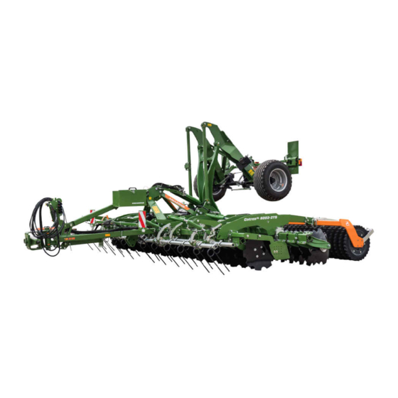
Amazone CatrosXL 4003-2TS Original Operating Manual (122 pages)
Trailed compact disc harrow
Brand: Amazone
|
Category: Farm Equipment
|
Size: 6 MB
Table of Contents
-
Diagrams7
-
Lists9
-
Intended Use25
-
Dimensions43
-
As Required93
-
Appendix113
-
Directories115
-
Glossary115
-
Index116
Advertisement

Amazone CatrosXL 4003-2TS Original Operating Manual (116 pages)
Trailed compact disk harrow
Brand: Amazone
|
Category: Farm Equipment
|
Size: 5 MB
Table of Contents
-
Listings9
-
Intended Use25
-
Wheel Chocks30
-
Safety Chain31
-
Gewindepack40
-
Dimensions41
-
Appendix107
-
Directories110
-
Glossary110
-
Index111

Amazone CatrosXL 4003-2TS Original Operating Manual (122 pages)
Trailed compact disc harrow
Brand: Amazone
|
Category: Farm Equipment
|
Size: 6 MB
Table of Contents
-
-
Diagrams7
-
Lists9
-
Intended Use25
-
Dimensions43
-
-
As Required93
Advertisement

Amazone CatrosXL 4003-2TS Original Operating Manual (122 pages)
Trailed compact disk harrow
Brand: Amazone
|
Category: Farm Equipment
|
Size: 6 MB
Table of Contents
-
Listings9
-
Intended Use25
-
Rating Plate38
-
Gewindepack40
-
Dimensions42
-
Each Other91

Amazone CatrosXL 4003-2TS Operating Instructions Manual (116 pages)
Trailed compact disc harrow
Brand: Amazone
|
Category: Farm Equipment
|
Size: 7 MB
Table of Contents
-
-
Stop Tap31
-
Wheel Chocks32
-
Running Gear34
-
Safety Chain
36-
Crushboard37
-
Straw Harrow38
-
-
-
-
Discs39
-
Rollers41
-
Rear Harrow45
-
-
Cab68
-
-
-
11 Appendix
108 -
12 Indexes
110
Advertisement