Amazone CatrosXL 4003-2TS Original Operating Manual
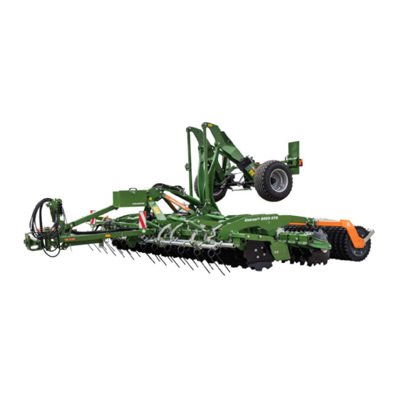
Trailed compact disc harrow
Hide thumbs
Also See for CatrosXL 4003-2TS:
- Operating instructions manual (116 pages) ,
- Original operating manual (116 pages) ,
- Original operating manual (122 pages)

Related Manuals for Amazone CatrosXL 4003-2TS


Summary of Contents for Amazone CatrosXL 4003-2TS
- Page 1 Original operating manual Trailed compact disc harrow Catros 4003-2TS Catros 5003-2TS Catros 6003-2TS SmartLearning www.amazone.de...
- Page 2 Please enter the identification data of the implement. The identification data can be found on the rating plate.
-
Page 3: Table Of Contents
Checking the tractor suitability Special equipment 6.1.1 Calculating the required tractor characteristics Warning symbols 6.1.2 Determining the required coupling 4.4.1 Positions of the warning symbols devices 4.4.2 Layout of the warning symbols MG6828-EN-GB | X.1 | 03.03.2023 | © AMAZONE... - Page 4 Adjusting the working depth Releasing the safety chain 7.3.1 Adjusting the working depth of the discs 7.3.2 Hydraulic adjustment of the crushboard working depth 7.3.3 Adjust the working depth of the side guide plates MG6828-EN-GB | X.1 | 03.03.2023 | © AMAZONE...
- Page 5 102 11.1.2 Manoeuvring an implement with single-circuit hydraulic brake system 103 11.2 Loading the machine 11.2.1 Manoeuvring the implement onto a transport vehicle 11.2.2 Loading the implement with a crane MG6828-EN-GB | X.1 | 03.03.2023 | © AMAZONE...
-
Page 7: About This Operating Manual
WARNING Indicates a possible threat with moderate risk for severe physical injury or death. CAUTION Indicates a threat with low risk for light or moderately severe physical injuries. MG6828-EN-GB | X.1 | 03.03.2023 | © AMAZONE... -
Page 8: Further Instructions
Example: 1. Instruction 1 2. Instruction 2 1.2.3.1 Instructions and responses CMS-T-005678-B.1 Reactions to instructions are marked with an arrow. Example: 1. Instruction 1 Reaction to instruction 1 2. Instruction 2 MG6828-EN-GB | X.1 | 03.03.2023 | © AMAZONE... -
Page 9: Lists
Instructions that do not require a specific sequence are shown as a list with arrows. Example: Instruction Instruction Instruction 1.2.4 Lists CMS-T-000024-A.1 Lists without an essential order are shown as a list with bullets. Example: Point 1 Point 2 MG6828-EN-GB | X.1 | 03.03.2023 | © AMAZONE... -
Page 10: Item Numbers In Figures
A list of other applicable documents can be found in the Appendix. 1.4 Digital operating manual CMS-T-00002024-B.1 The digital operating manual and e-learning can be downloaded from the Info Portal on the AMAZONE website. 1.5 Your opinion is important CMS-T-000059-C.1 AMAZONEN-WERKE H. Dreyer SE & Co. KG Dear reader, our operating manuals are updated regularly. -
Page 11: Safety And Responsibility
2.1.2.1.1 Requirements for all persons working with the machine CMS-T-00002310-A.1 If the machine is used improperly, people can be injured or killed. To prevent accidents due to improper use, every person who works with MG6828-EN-GB | X.1 | 03.03.2023 | © AMAZONE... - Page 12 Farmers are basically familiar with working with agricultural implements and can instruct agricultural helpers in how to use the implements if necessary. They can perform odd tasks and simple maintenance and repair work on agricultural implements themselves. MG6828-EN-GB | X.1 | 03.03.2023 | © AMAZONE...
- Page 13 Passengers can fall, be run over and severely injured or killed due to machine movements. Ejected objects can hit and injure passengers. Do not let anybody ride on the machine. Do not let anybody climb onto the driving machine. MG6828-EN-GB | X.1 | 03.03.2023 | © AMAZONE...
- Page 14 Non-observance of the technical limits values of the machine can result in accidents and serious personal injury or even death. Moreover, the machine can be damaged. The technical limit values can be found in the Technical Data. Comply with the technical limit values. MG6828-EN-GB | X.1 | 03.03.2023 | © AMAZONE...
- Page 15 Missing warning symbols increase the risk of serious and lethal personal injury. Clean dirty warning symbols. Immediately replace any damaged and illegible warning symbols. Put the intended warning symbols on spare parts. MG6828-EN-GB | X.1 | 03.03.2023 | © AMAZONE...
-
Page 16: Knowing And Preventing Dangers
Never look for leaks with your bare hands. Keep your body and face away from leaks. If liquids penetrate the body, consult a doctor immediately. MG6828-EN-GB | X.1 | 03.03.2023 | © AMAZONE... -
Page 17: Safe Operation And Handling Of The Machine
Use only suitable tractors for coupling and transporting the implement. When the implement is coupled onto the tractor, make sure that the tractor's connecting device meets the implement requirements. Couple the implement properly to the tractor. MG6828-EN-GB | X.1 | 03.03.2023 | © AMAZONE... - Page 18 If the machine is not properly prepared for road travel, it can result in serious traffic accidents. Check the lighting and identification for road travel for proper function. Remove coarse dirt from the implement. Follow the instructions in the section "Preparing the implement for road travel". MG6828-EN-GB | X.1 | 03.03.2023 | © AMAZONE...
-
Page 19: Safe Maintenance And Modification
To ensure that the operating permit remains valid in accordance with national and international regulations, ensure that the specialist workshop only uses conversion parts, spare parts and special equipment approved by AMAZONE. MG6828-EN-GB | X.1 | 03.03.2023 | © AMAZONE... - Page 20 Remove the ignition key and carry it with you. Remove the key from the battery circuit breaker. Wait until all parts that are still running come to a stop and that hot parts cool down. MG6828-EN-GB | X.1 | 03.03.2023 | © AMAZONE...
- Page 21 Never linger under raised implement parts. If you have to work on or under raised machine parts, lower the implement parts or secure the raised implement parts with a mechanical support or hydraulic locking device. MG6828-EN-GB | X.1 | 03.03.2023 | © AMAZONE...
- Page 22 CMS-T-00002325-B.1 Special equipment, accessories, and spare parts Special equipment, accessories, and spare parts that do not meet AMAZONE requirements can impede the operational safety of the implement and cause accidents. Only use original parts or parts that meet AMAZONE requirements.
-
Page 23: Safety Routines
If you are not sure if the protective equipment is properly installed and functional, have the protective equipment checked by a qualified specialist workshop. Make sure that the protective devices are properly installed and functional before any work on the implement. Replace damaged protective equipment. MG6828-EN-GB | X.1 | 03.03.2023 | © AMAZONE... - Page 24 When climbing up and down, never hold onto the control elements. Accidental actuation of control elements can unintentionally activate potentially dangerous functions. When climbing down, never jump off of the machine. MG6828-EN-GB | X.1 | 03.03.2023 | © AMAZONE...
-
Page 25: Intended Use
AMAZONE. Uses other than those specified under the intended use are considered as improper. The manufacturer is not liable for any damage resulting from improper use, solely the operator is responsible. MG6828-EN-GB | X.1 | 03.03.2023 | © AMAZONE... -
Page 26: Product Description
10 Side disc Clearer system 11 Left side guide plate 12 Discs 13 Threaded spindle for aligning the disc gangs 14 Leading tool 15 Working depth adjustment for leading tool 16 Threaded cartridge MG6828-EN-GB | X.1 | 03.03.2023 | © AMAZONE... -
Page 27: Implement With Support Wheels
Support wheel Compressed air tank Central lubrication Brake valve of the dual-circuit pneumatic brake Emergency brake valve of the single-circuit system hydraulic brake system 10 Threaded spindle for aligning the support wheel Jack MG6828-EN-GB | X.1 | 03.03.2023 | © AMAZONE... -
Page 28: Implement With Greendrill
4.3 Special equipment CMS-T-00004254-C.1 Special equipment is equipment that is not fitted on the implement or is only available in certain markets. The sales documents provide information on the MG6828-EN-GB | X.1 | 03.03.2023 | © AMAZONE... - Page 29 Lighting and identification for road travel Single-circuit hydraulic brake system Crushboard Cutting roller Spring blade system Clearer system Side guide plate Harrow system Support wheels Ballast weights Central lubrication Catch crop conveyor section with distributor head MG6828-EN-GB | X.1 | 03.03.2023 | © AMAZONE...
-
Page 30: Warning Symbols
4.4.1 Positions of the warning symbols CMS-T-00004257-E.1 M 273 MD084 MD174 MD100 MD278 MD273 M 155 M 082 M 094 M 097 MD211 MD210 MD212 MD199 MD100 MD155 D0 9 CMS-I-00003528 MD084 MD084 CMS-I-00003482 MG6828-EN-GB | X.1 | 03.03.2023 | © AMAZONE... - Page 31 4 | Product description Warning symbols MD100 MD101 MD082 MD084 MD101 MD100 CMS-I-00003531 MD082 MD078 CMS-I-00004516 MD154 CMS-I-00007680 MG6828-EN-GB | X.1 | 03.03.2023 | © AMAZONE...
-
Page 32: Layout Of The Warning Symbols
A warning symbol consists of two fields: Field 1 shows the following: A pictogram depicting the danger area, CMS-I-00000416 surrounded by triangular safety symbol The order number Field 2 shows a pictogram depicting how to avoid the danger. MG6828-EN-GB | X.1 | 03.03.2023 | © AMAZONE... -
Page 33: Description Of The Warning Symbols
Do not let anybody climb onto the driving implement. CMS-I-000081 MD 084 Risk of crushing for the whole body from lowering implement parts Make sure that there is nobody standing in the danger area. CMS-I-000454 MG6828-EN-GB | X.1 | 03.03.2023 | © AMAZONE... - Page 34 Never look for leaks in hydraulic hose lines using your hand or fingers. Never attempt to plug leaks in hydraulic hose lines using your hand or fingers. If you are injured by hydraulic oil, consult a doctor immediately. CMS-I-000216 MG6828-EN-GB | X.1 | 03.03.2023 | © AMAZONE...
- Page 35 Only attach the lifting equipment at the marked positions. CMS-I-00002252 MD 102 Risk due to unintentional starting and rolling away of the machine Before performing any work, secure the implement against unintentional starting and rolling away. CMS-I-00002253 MG6828-EN-GB | X.1 | 03.03.2023 | © AMAZONE...
- Page 36 CMS-I-00000450 MD 174 Risk of rolling over due to unsecured implement Secure the implement against rolling away. To do so, use the parking brake and/or wheel chocks. CMS-I-00000458 MG6828-EN-GB | X.1 | 03.03.2023 | © AMAZONE...
- Page 37 MD 278 Severe injuries due to incorrect handling of the hydraulic accumulator when it is under pressure Have the pressurised hydraulic accumulator checked and repaired only by a qualified specialist workshop. MD278 CMS-I-00007679 MG6828-EN-GB | X.1 | 03.03.2023 | © AMAZONE...
-
Page 38: Lighting And Identification For Road Travel
4.5.2 Front lighting and identification CMS-T-00009971-A.1 Warning signs Reflector, white CMS-I-00004522 NOTE The lighting and identification for road travel can vary depending on the national regulations. MG6828-EN-GB | X.1 | 03.03.2023 | © AMAZONE... -
Page 39: Threaded Cartridge
Permissible technical trailer load for a drawbar trailer vehicle with pneumatic brake A0 Permissible technical drawbar load A1 Permissible technical axle load for axle 1 A2 Permissible technical axle load for axle 2 MG6828-EN-GB | X.1 | 03.03.2023 | © AMAZONE... -
Page 40: Other Information On The Implement
The figure indicates that the traction assistance is switched on when the switch tap is in Position "1" and is switched off when the switch tap is in Position "0". ME1678 CMS-I-00008055 MG6828-EN-GB | X.1 | 03.03.2023 | © AMAZONE... -
Page 41: Single-Circuit Hydraulic Brake System
With the setting lever, the tilt of the harrow systems, the double harrow, the spring blade system and the spring clearer system can be conveniently adjusted. Setting lever in parking position CMS-I-00002241 MG6828-EN-GB | X.1 | 03.03.2023 | © AMAZONE... - Page 42 4 | Product description Setting lever for the trailing elements Setting lever in set position CMS-I-00007912 MG6828-EN-GB | X.1 | 03.03.2023 | © AMAZONE...
-
Page 43: Technical Data
Catros 6003-2TS Number of discs Disc thickness 6 mm Disc diameter 61 cm Working depth 5-16 cm 5.3 Permitted mounting categories CMS-T-00004236-A.1 Lower link mounting Category 3, Category 4N and Category K700 MG6828-EN-GB | X.1 | 03.03.2023 | © AMAZONE... -
Page 44: Optimal Working Speed
The workplace-related emission sound pressure level is lower than 70 dB(A), measured in operating condition at the ear of the tractor driver with the cab closed. The emission sound pressure level mainly depends on the vehicle used. MG6828-EN-GB | X.1 | 03.03.2023 | © AMAZONE... -
Page 45: Drivable Slope Inclination
On left in direction of travel 15 % On right in direction of travel 15 % Up the slope and down the slope Up the slope 15 % Down the slope 15 % MG6828-EN-GB | X.1 | 03.03.2023 | © AMAZONE... -
Page 46: Preparing The Machine
Front axle load of the operational tractor without mounted implement or ballast weights Rear axle load of the operational tractor without mounted implement or ballast weights Total weight of front-mounted implement or front ballast Drawbar load MG6828-EN-GB | X.1 | 03.03.2023 | © AMAZONE... - Page 47 F c T b 0,2 T b Vmin Vmin Vmin CMS-I-00003504 2. Calculate the actual front axle load. × × - × G a b T b F c Vtat Vtat Vtat CMS-I-00005422 MG6828-EN-GB | X.1 | 03.03.2023 | © AMAZONE...
- Page 48 Tyre load according to according to capacity for two tractor operating calculation tractor tyres manual ≤ Minimum front ballasting ≤ Total weight ≤ ≤ Front axle load ≤ ≤ Rear axle load MG6828-EN-GB | X.1 | 03.03.2023 | © AMAZONE...
-
Page 49: Determining The Required Coupling Devices
Rotating drawbar eye 50 mm Non-swivel clevis coupling Rotating drawbar eye Lower link hitch Lower link traverse Check whether the coupling device of the tractor is compatible with the coupling device of the implement. MG6828-EN-GB | X.1 | 03.03.2023 | © AMAZONE... -
Page 50: Comparing The Permissible Dc Value With Actual Dc Value
6.2 Coupling the implement CMS-T-00004246-P.1 6.2.1 Removing the safety device against unauthorised use CMS-T-00005089-B.1 1. Unlock the padlock. 2. Remove the safety device against unauthorised use from the hitch device. CMS-I-00003534 MG6828-EN-GB | X.1 | 03.03.2023 | © AMAZONE... -
Page 51: Driving The Tractor Towards The Implement
Stickers are applied on the implement for the markings, which illustrate the respective hydraulic functions. The tractor control unit is used with different types of actuation, depending on the hydraulic function: CMS-I-00000121 MG6828-EN-GB | X.1 | 03.03.2023 | © AMAZONE... - Page 52 Risk of injury or even death If the hydraulic hose lines are incorrectly connected, the hydraulic functions may be faulty. When coupling the hydraulic hose lines, observe the coloured markings on the hydraulic plugs. MG6828-EN-GB | X.1 | 03.03.2023 | © AMAZONE...
-
Page 53: Coupling The Power Supply
3. Check the lighting on the implement for proper function. CMS-I-00001048 6.2.6 Coupling the power supply for the central lubrication CMS-T-00006309-C.1 1. Connect the plug 1 for the power supply to the central lubrication. CMS-I-00004518 MG6828-EN-GB | X.1 | 03.03.2023 | © AMAZONE... -
Page 54: Coupling The Brake System
2 from the empty coupling. 6. Couple the red coupling head with the coupling marked in red on the tractor. 7. Route the brake lines with sufficient freedom of movement and without chafing or pinching points. MG6828-EN-GB | X.1 | 03.03.2023 | © AMAZONE... - Page 55 4. Attach the ripcord to a sturdy point on the tractor. 5. Actuate the tractor brake several times with the tractor motor running. The pressure accumulator of the emergency brake will be charged. CMS-I-00007789 MG6828-EN-GB | X.1 | 03.03.2023 | © AMAZONE...
-
Page 56: Connecting The Coupling Device
2. Pull out the linch pin from the pin. 3. Pull out the pin. 4. Swivel up the jack. 5. Insert the pin. 6. Secure the pin with a linch pin. CMS-I-00003350 MG6828-EN-GB | X.1 | 03.03.2023 | © AMAZONE... - Page 57 2. Pull out the linch pin from the pin. 3. Pull out the pin. 4. Swivel up the jack. 5. Insert the pin. CMS-I-00003552 6. Secure the pin with a linch pin. MG6828-EN-GB | X.1 | 03.03.2023 | © AMAZONE...
-
Page 58: Removing The Wheel Chocks
6.3 Preparing the implement for operation CMS-T-00004238-L.1 6.3.1 Unfolding the sections CMS-T-00004426-E.1 1. Completely raise the implement. 2. Actuate the "blue" tractor control unit. The sections unfold. 3. Unfold the sections up to the end position. MG6828-EN-GB | X.1 | 03.03.2023 | © AMAZONE... -
Page 59: Adjusting The Trailing Elements
CMS-T-00012143-A.1 1. Pull out the both linch pins on both adjustment units. The next step can also be performed with the setting lever. 2. Turn the harrow to the desired position. CMS-I-00007852 MG6828-EN-GB | X.1 | 03.03.2023 | © AMAZONE... - Page 60 CMS-T-00012149-A.1 1. Pull out the both linch pins on both adjustment units. The next step can also be performed with the setting lever. 2. Turn the harrow to the desired position. CMS-I-00007866 MG6828-EN-GB | X.1 | 03.03.2023 | © AMAZONE...
- Page 61 1. Pull out the the linch pins 1 on both adjustment units. The next step can also be performed with the setting lever. 2. Turn the harrow to the desired position. CMS-I-00007871 MG6828-EN-GB | X.1 | 03.03.2023 | © AMAZONE...
- Page 62 1. Pull out the linch pin 1 on both adjustment units of a harrow bar. The next step can also be performed with the setting lever. 2. Turn the harrow beam to the desired position. CMS-I-00007882 MG6828-EN-GB | X.1 | 03.03.2023 | © AMAZONE...
- Page 63 6.3.2.6 Adjusting the scraper on the clearer system WW 142 HI CMS-T-00012171-A.1 In case of wear, the scrapers on clearer system WW 142 HI can be moved closer towards the angle profile roller. MG6828-EN-GB | X.1 | 03.03.2023 | © AMAZONE...
-
Page 64: Installing Ballast Weights
3. Screw two ballast weights together respectively. CMS-I-00000533 6.3.4 Adjusting the scraper to the roller CMS-T-00000076-F.1 The scrapers on the roller are set at the factory. The scrapers can be adapted to the working conditions. MG6828-EN-GB | X.1 | 03.03.2023 | © AMAZONE... -
Page 65: Adjusting The Central Lubrication
3. Tighten the bolt 1 . 4. Check the distances when the implement is lowered. CMS-I-00000521 6.3.5 Adjusting the central lubrication CMS-T-00006314-C.1 Pause times Blue rotary knob Hours Lubrication times Red rotary knob Minutes MG6828-EN-GB | X.1 | 03.03.2023 | © AMAZONE... -
Page 66: Preparing The Machine For Road Travel
6.4 Preparing the machine for road travel CMS-T-00004244-K.1 6.4.1 Securing the cutting roller CMS-T-00004963-D.1 1. Lift the cutting roller using the "beige" tractor control unit. 2. Close the stop tap for the cutting roller. CMS-I-00003326 MG6828-EN-GB | X.1 | 03.03.2023 | © AMAZONE... -
Page 67: Moving The Harrow Into Transport Position
The next step can also be performed with the setting lever. If the harrow tines exceed the transport width when the implement is folded: Turn the harrow bar to a flatter tilt. MG6828-EN-GB | X.1 | 03.03.2023 | © AMAZONE... - Page 68 CMS-I-00007907 6.4.2.4 Moving the double harrow CXS into transport position CMS-T-00012328-A.1 On folding implements, the harrow tines together with the road safety bars may not exceed the transport width of 3 m. MG6828-EN-GB | X.1 | 03.03.2023 | © AMAZONE...
-
Page 69: Putting On The Road Safety Bars
1. Set the working depth of the discs to the minimum. 2. Completely lift the implement with the lower link or the hydraulic drawbar. 3. Actuate the "blue" tractor control unit. The sections fold. MG6828-EN-GB | X.1 | 03.03.2023 | © AMAZONE... -
Page 70: Aligning The Implement At Transport Height
The correct transport height is reached at the specified height of the drawbar pivot point. A spirit level is attached to the implement frame. The spirit level shows the alignment of the implement in the direction of travel. MG6828-EN-GB | X.1 | 03.03.2023 | © AMAZONE... -
Page 71: Locking The Tractor Control Units
"yellow" tractor control unit. 6.4.6 Locking the tractor control units CMS-T-00006337-D.1 Depending on the equipment, the tractor control units are locked mechanically or electrically. MG6828-EN-GB | X.1 | 03.03.2023 | © AMAZONE... -
Page 72: Using The Machine
2. Turn the traffic safety bars 1 by 180°, place on top of each other on the brackets 2 . 3. Secure the road safety bars with tensioners 3 . CMS-I-00000518 MG6828-EN-GB | X.1 | 03.03.2023 | © AMAZONE... -
Page 73: Adjusting The Working Depth
4 and the middle of pin 8 . 15. Set the adjustment spindle on the second disc array to the same length. 16. Put the hand lever in parking position. 17. Secure the hand lever with a linch pin. MG6828-EN-GB | X.1 | 03.03.2023 | © AMAZONE... - Page 74 3. Turn the side disc up or down in the elongated slots. NOTE CMS-I-00003202 The specified working width is only achieved when all of the discs are set to the same working depth. 4. Tighten the bolts. MG6828-EN-GB | X.1 | 03.03.2023 | © AMAZONE...
-
Page 75: Hydraulic Adjustment Of The Crushboard Working Depth
CMS-I-00003484 CMS-I-00003277 IMPORTANT Damage due to the side guide plates being set too deep Set the side guide plates at a distance of at least 30 mm from the ground. MG6828-EN-GB | X.1 | 03.03.2023 | © AMAZONE... -
Page 76: Lifting The Running Gear And Using The Vibration Compensation
7.5 Lifting the running gear and not using the vibration compensation CMS-T-00012243-A.1 For optimal penetration of the tools into the soil, swivel the running gear completely in. In this case, the vibration compensation will not be used. MG6828-EN-GB | X.1 | 03.03.2023 | © AMAZONE... -
Page 77: Aligning The Implement Horizontally
7.6.2 Aligning the implement horizontally with lower link hitch CMS-T-00004957-B.1 A spirit level is attached to the implement frame. The spirit level shows the alignment of the implement in the direction of travel. MG6828-EN-GB | X.1 | 03.03.2023 | © AMAZONE... -
Page 78: Aligning The Implement Horizontally With Hydraulic Drawbar
The cutting roller chops up crop residues and catch crops. The cutting roller is automatically pre- tensioned using a hydraulic pressure accumulator. A stop tap is attached to the hydraulic pressure accumulator. MG6828-EN-GB | X.1 | 03.03.2023 | © AMAZONE... -
Page 79: Driving On The Headlands
The roller supports the implement. When the direction of the implement matches that of the direction of travel, lower with the lower link or with the "yellow" tractor control unit. MG6828-EN-GB | X.1 | 03.03.2023 | © AMAZONE... -
Page 80: Turning On The Running Gear On The Headlands
When the direction of the implement matches that of the direction of travel, Lower the lower link and actuate the "yellow" tractor control unit actuate both "yellow" tractor control units and lower the implement. MG6828-EN-GB | X.1 | 03.03.2023 | © AMAZONE... -
Page 81: Eliminating Faults
Grease nipple blocked see page 76 An implement with single-circuit The spring cotter pin is in the see page 77 hydraulic brake system is braked horizontal brake position. by the emergency brake. MG6828-EN-GB | X.1 | 03.03.2023 | © AMAZONE... - Page 82 CMS-I-00004521 4. Clean faulty lubrication points. 5. Reinstall the grease nipple on the faulty lubrication point. 6. Pump in grease again through the grease nipple MG6828-EN-GB | X.1 | 03.03.2023 | © AMAZONE...
- Page 83 An implement with single-circuit hydraulic brake system is braked by the emergency brake CMS-T-00012111-A.1 1. Insert the spring cotter pin into the brake valve from the front. 2. Position the spring cotter pin vertically. 3. Relieve the brake pressure using the hand pump. CMS-I-00007786 MG6828-EN-GB | X.1 | 03.03.2023 | © AMAZONE...
-
Page 84: Parking The Machine
1. Take the wheel chocks out from the holder. 2. For folding wheel chocks, actuate the press button and unfold the wheel chock. 3. Place the wheel chocks under the wheels. CMS-I-00007809 MG6828-EN-GB | X.1 | 03.03.2023 | © AMAZONE... -
Page 85: Disconnecting The Coupling Device
CMS-T-00004574-F.1 1. Relieve the tractor's lower link 1 . 2. Release the lower link catch hook 2 . 3. Uncouple the tractor lower links from the implement from the tractor seat. CMS-I-00003346 MG6828-EN-GB | X.1 | 03.03.2023 | © AMAZONE... -
Page 86: Uncoupling The Ball Coupling Or Drawbar Eye
CMS-I-00003557 9.3.2.3 Uncoupling the ball coupling CMS-T-00004579-C.1 To lift the ball hitch coupling from the hitch ball: Lift the hydraulic drawbar using the "yellow" tractor control unit. CMS-I-00003558 MG6828-EN-GB | X.1 | 03.03.2023 | © AMAZONE... -
Page 87: Driving The Tractor Away From The Implement
3. Uncouple the yellow coupling head of the brake line 1 from the tractor. 4. Couple the yellow coupling head with the empty coupling on the implement. CMS-I-00003559 5. Close the tractor coupling head caps. MG6828-EN-GB | X.1 | 03.03.2023 | © AMAZONE... -
Page 88: Uncoupling The Single-Circuit Hydraulic Brake System
2. Uncouple the hydraulic plug from the hydraulic socket. CMS-I-00003560 9.6 Uncoupling the power supply CMS-T-00001402-H.1 1. Pull out the plug 1 for the power supply. CMS-I-00001048 2. Hang the plugs 1 in the hose cabinet. CMS-I-00001248 MG6828-EN-GB | X.1 | 03.03.2023 | © AMAZONE... -
Page 89: Disconnecting The Hydraulic Hose Lines
4. Put the dust caps on the hydraulic sockets. CMS-I-00001065 5. Hang the hydraulic hose lines 1 in the hose cabinet. CMS-I-00001250 9.8 Releasing the safety chain CMS-T-00004315-C.1 Release the safety chain from the tractor. CMS-I-00007814 MG6828-EN-GB | X.1 | 03.03.2023 | © AMAZONE... -
Page 90: Putting On The Safety Device
Putting on the safety device against unauthorised use 9.9 Putting on the safety device against unauthorised use CMS-T-00005090-B.1 1. Put the safety device against unauthorised use on the hitch device. 2. Put on the padlock. CMS-I-00003534 MG6828-EN-GB | X.1 | 03.03.2023 | © AMAZONE... -
Page 91: Repairing The Machine
Every 10 operating hours / daily Checking the lower link pins see page 88 Every 50 operating hours / weekly Checking the hydraulic hose lines see page 89 Checking the wheels see page 90 MG6828-EN-GB | X.1 | 03.03.2023 | © AMAZONE... - Page 92 46 cm 1. Slightly raise the implement. CMS-I-00002450 2. Loosen the 4 bolts 1 for the disc fastening. 3. Remove the washer 2 . 4. Fasten the new disc with the 4 bolts. MG6828-EN-GB | X.1 | 03.03.2023 | © AMAZONE...
-
Page 93: After Initial Operation
The discs are not standing on the ground. 3. Loosen the lock nuts 1 on all of the adjustment spindles. CMS-I-00003204 4. Align the disc gangs using the hexagonal profile 2 on the adjustment spindle. MG6828-EN-GB | X.1 | 03.03.2023 | © AMAZONE... -
Page 94: Checking The Rollers
CMS-I-00000099 10.1.6 Checking the lower link pins CMS-T-00004233-C.1 INTERVAL Every 10 operating hours daily Criteria for visual inspection of the lower link pins: Cracks Fractures Permanent deformations Permissible wear: 2 mm MG6828-EN-GB | X.1 | 03.03.2023 | © AMAZONE... -
Page 95: Checking The Hydraulic Hose Lines
Hydraulic hose lines must not be more than 6 years old. 3. Check the manufacturing date 1 . CMS-I-00000532 4. Have any worn, damaged or aged hydraulic hose lines immediately replaced at a specialist workshop. 5. Retighten loose bolted connections. MG6828-EN-GB | X.1 | 03.03.2023 | © AMAZONE... -
Page 96: Checking The Wheels
"yellow" tractor control unit Lift the support wheels by a few centimetres using the lower link or hydraulic drawbar. The wheels of the running gear or the support wheels can rotate freely. MG6828-EN-GB | X.1 | 03.03.2023 | © AMAZONE... -
Page 97: Checking The Brake Pads
Pressure drop in the pneumatic brake system maximum of 0.15 bar in 10 minutes Air pressure in the compressed air tank 6 bar-8.2 bar Brake cylinder pressure 0 bar when the brake is not actuated MG6828-EN-GB | X.1 | 03.03.2023 | © AMAZONE... -
Page 98: Draining The Compressed Air Tank
1. Check the compressed air tank for damage and corrosion. If the compressed air tank is damaged or corroded, have the compressed air tank replaced by a specialist workshop. 3. Check the tensioning belts of the compressed air tank. MG6828-EN-GB | X.1 | 03.03.2023 | © AMAZONE... -
Page 99: Cleaning The Compressed Air Line Filter
4. Remove the rubber seal. 5. Replace damaged parts. 6. Clean the sealing surfaces, seal ring and compressed air line filter. 7. Grease the sealing surfaces, seal ring and compressed air line filter. CMS-I-00003573 MG6828-EN-GB | X.1 | 03.03.2023 | © AMAZONE... -
Page 100: Checking The Axle Bolts
Category 3 34.5 mm M20 8.8 420 Nm Category 4 48 mm M20 8.8 420 Nm Category 4N 48 mm M20 8.8 420 Nm Category K700 56 mm M20 8.8 420 Nm MG6828-EN-GB | X.1 | 03.03.2023 | © AMAZONE... -
Page 101: Checking The Ball Hitch Coupling
D50 (LI010) 51.5 mm M16 10.9 300 Nm D50 (LI059) 51.5 mm M20 10.9 560 Nm D50 (LI011) 51.5 mm M20 8.8 410 Nm D50 (LI060) 52.5 mm M20 10.9 560 Nm MG6828-EN-GB | X.1 | 03.03.2023 | © AMAZONE... -
Page 102: Checking The Central Lubrication
If the fill level is low in the tank fill in grease through the filling nipple 3 until just -MAX- below the "MAX" mark. If grease emerged on the pressure relief valve -MIN- see "Eliminating faults". CMS-I-00004515 MG6828-EN-GB | X.1 | 03.03.2023 | © AMAZONE... -
Page 103: Cleaning The Implement
Always maintain a minimum distance of 30 cm between the high-pressure nozzle and the implement. Do not exceed a water pressure of 120 bar. Clean the machine with a high-pressure cleaner or a hot water high-pressure cleaner. MG6828-EN-GB | X.1 | 03.03.2023 | © AMAZONE... -
Page 104: Lubricating The Implement
Only grease the implement with the lubricants listed in the technical data. CMS-I-00002270 Press the dirty grease completely out of the bearings. MG6828-EN-GB | X.1 | 03.03.2023 | © AMAZONE... -
Page 105: Overview Of Lubrication Points
10 | Repairing the machine Lubricating the implement 10.3.1 Overview of lubrication points CMS-T-00004969-C.1 CMS-I-00003571 Every 50 operating hours CMS-I-00003569 CMS-I-00002245 MG6828-EN-GB | X.1 | 03.03.2023 | © AMAZONE... - Page 106 10 | Repairing the machine Lubricating the implement CMS-I-00003568 CMS-I-00003567 CMS-I-00003563 CMS-I-00003565 CMS-I-00003566 CMS-I-00003564 Every 200 operating hours CMS-I-00004519 MG6828-EN-GB | X.1 | 03.03.2023 | © AMAZONE...
-
Page 107: Lubricating The Wheel Hubs
Every 500 operating hours 1. Remove the wheel hub cap from the wheel hub. 2. Fill up the wheel hub cap with grease. 3. Put the wheel hub cap on the wheel hub. MG6828-EN-GB | X.1 | 03.03.2023 | © AMAZONE... -
Page 108: Preparing The Implement For Transport
1. Press in the control knob 1 of the release valve up to the stop Turn the hand lever 2 of the brake valve to the position. The compressed air that acts on the brakes escapes. 2. Manoeuvre the implement. CMS-I-00007826 MG6828-EN-GB | X.1 | 03.03.2023 | © AMAZONE... -
Page 109: Manoeuvring An Implement With Single-Circuit Hydraulic Brake System
4 on the brake valve 3 . NOTE The hydraulic cylinders of the hydraulic brakes must be completely retracted. The required pumping time is several minutes. 2. Manoeuvre the implement. CMS-I-00007787 MG6828-EN-GB | X.1 | 03.03.2023 | © AMAZONE... -
Page 110: Loading The Machine
Only attach the slings for lifting at the marked lashing points. 1. Attach the slings for lifting on the intended lashing points. 2. Slowly lift the implement. MG6828-EN-GB | X.1 | 03.03.2023 | © AMAZONE... - Page 111 1. Put the implement on the transport vehicle. 2. Attach the lashing straps at the marked points. 3. Lash down the implement in compliance with the national regulations for load securing. MG6828-EN-GB | X.1 | 03.03.2023 | © AMAZONE...
- Page 112 2. Return batteries to the distributor Dispose of batteries at a collection point. 3. Put recyclable materials in the recycling. 4. Treat operating materials like hazardous waste. 5. Have coolants disposed of by a specialist workshop. MG6828-EN-GB | X.1 | 03.03.2023 | © AMAZONE...
-
Page 113: Replacing The Discs 86 13.1 Bolt Tightening Torques
380 Nm 290 Nm 405 Nm 485 Nm 27 mm M18x1.5 325 Nm 460 Nm 550 Nm 410 Nm 580 Nm 690 Nm 30 mm M20x1.5 460 Nm 640 Nm 770 Nm MG6828-EN-GB | X.1 | 03.03.2023 | © AMAZONE... -
Page 114: Checking The Disc Carrier Connection 87 13.2 Other Applicable Documents
174 Nm 8.4 Nm 242 Nm 20.4 Nm 342 Nm 40.7 Nm 470 Nm 70.5 Nm 589 Nm 13.2 Other applicable documents CMS-T-00000615-A.1 Tractor operating manual Operating manual for the GreenDrill 200-E MG6828-EN-GB | X.1 | 03.03.2023 | © AMAZONE... - Page 115 Tractor In this operating manual, the designation tractor is always used, even for other agricultural tractor units. Implements are mounted on the tractor or towed by the tractor. MG6828-EN-GB | X.1 | 03.03.2023 | © AMAZONE...
- Page 116 Hydraulic hose lines uncoupling cleaning Implement Emergency brake Clearer system WW 142 HI Adjusting the scraper Compressed air line filter Float position of hydraulic valves cleaning Folding 52, 63, 66 Secure sections MG6828-EN-GB | X.1 | 03.03.2023 | © AMAZONE...
- Page 117 Performance characteristics of the tractor Pneumatic brake system checking Implement coupling loading and unloading repairing Power supply coupling Intended use uncoupling Product description Jack Position Rating plate swivelling down 79, 80 swivelling up 50, 51 additional MG6828-EN-GB | X.1 | 03.03.2023 | © AMAZONE...
- Page 118 Tractor lower link Position coupling uncoupling Side discs adjustment Trailing elements Position adjustment 53, 53, 54, 54, 55, 55, 56, 56, 57, 57 Position Side guide plates Adjust the working depth Tyre inflation pressure MG6828-EN-GB | X.1 | 03.03.2023 | © AMAZONE...
- Page 119 Wheel hubs lubricating Wheels checking Working depth adjustment Position Synchronising the hydraulic cylinders Working depth Adjusting the side guide plates hydraulically Hydraulic crushboard adjustment Manual disc adjustment Side discs, adjusting Working speed MG6828-EN-GB | X.1 | 03.03.2023 | © AMAZONE...
- Page 122 AMAZONEN-WERKE H. DREYER SE & Co. KG Postfach 51 49202 Hasbergen-Gaste Germany +49 (0) 5405 501-0 amazone@amazone.de www.amazone.de MG6828-EN-GB | X.1 | 03.03.2023 | © AMAZONE...
Need help?
Do you have a question about the CatrosXL 4003-2TS and is the answer not in the manual?
Questions and answers