
Related Manuals for Amazone Cirrus Series


Summary of Contents for Amazone Cirrus Series
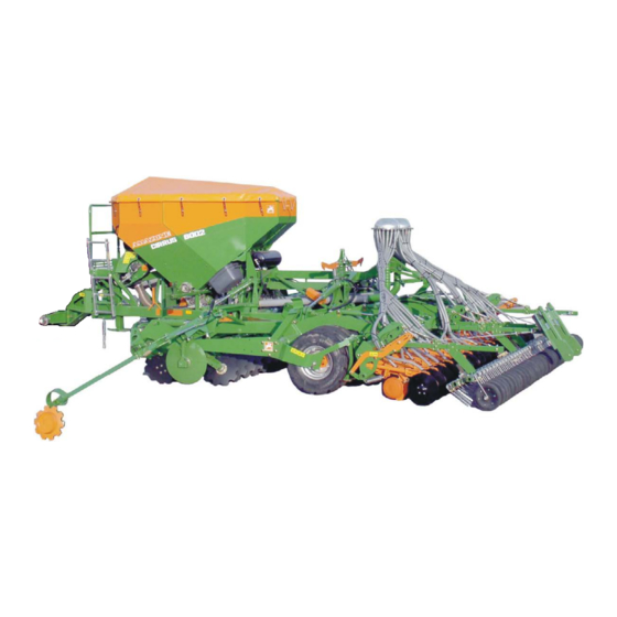
- Page 1 Operating Manual Cirrus 3002 / 4002 / 6002 Please read this operating manual before first com- missioning. MG3994 BAH0049-1 09.14 Keep it in a safe place for future use.
- Page 2 Reading the instruction manual and to adhere to it should not appear to be inconvenient and superfluous as it is not enough to hear from others and to realise that a machine is good, to buy it and to believe that now everything would work by itself.
- Page 3 + 49 (0)5405 501-234 E-mail: amazone@amazone.de Spare part orders Spare parts lists are freely accessible in the spare parts portal at www.amazone.de. Please send orders to your AMAZONE dealer. Formalities of the operating manual Document number: MG3994 Compilation date: 09.14 ...
- Page 4 Send us your suggestions by fax. AMAZONEN-WERKE H. DREYER GmbH & Co. KG Postfach 51 D-49202 Hasbergen Tel.: + 49 (0)5405 501-0 Fax: + 49 (0)5405 501-234 E-mail: amazone@amazone.de Cirrus BAH0049-1 09.14...
-
Page 5: Table Of Contents
Table of Contents User Information ..................10 Purpose of the document ....................... 10 Locations in the operating manual ..................10 Diagrams used ........................10 General Safety Instructions ..............11 Obligations and liability ......................11 Representation of safety symbols ..................13 Organisational measures ....................... - Page 6 Table of Contents Dual-circuit pneumatic service braking system ..............61 5.3.1 Coupling the brake and supply lines ..................62 5.3.2 Uncoupling the brake and supply lines ................. 63 Hydraulic operating brake system ..................64 5.4.1 Coupling the hydraulic operating brake system ..............64 5.4.2 Uncoupling the hydraulic operating brake system ..............
- Page 7 Table of Contents 7.1.3 Connecting the pneumatic service brake system ..............109 7.1.4 Connecting the hydraulic service brake system ..............110 Uncoupling the machine ...................... 111 Coupling the hydraulic pump (optional) ................114 7.3.1 Connecting the hydraulic pump ................... 114 7.3.2 Uncoupling the hydraulic pump....................
- Page 8 Table of Contents 10.10.1 Turning on the axle ......................166 10.10.2 Turning on the roller (except Cirrus 3002) ................166 10.11 End of work on the field ....................... 167 10.12 Emptying the hopper and/or dosing unit ................168 10.12.1 Emptying the seed hopper ....................168 10.12.2 Emptying the dosing unit .....................
- Page 9 Table of Contents 12.8 Bolt tightening torques ......................204 Hydraulic system diagrams ..............205 13.1 Hydraulic system diagram of the Cirrus 3002 Special ............205 13.2 Hydraulic system diagram of the Cirrus 4002 / 6002 ............207 Cirrus BAH0049-1 09.14...
-
Page 10: User Information
User Information User Information The User Information section supplies information on use of the oper- ating manual. Purpose of the document This operating manual • Describes the operation and maintenance of the machine. • Provides important information on safe and efficient handling of the machine. -
Page 11: General Safety Instructions
General Safety Instructions General Safety Instructions This section contains important information on safe operation of the machine. Obligations and liability Comply with the instructions in the operating manual Knowledge of the basic safety information and safety regulations is a basic requirement for safe handling and fault-free machine operation. Obligations of the operator The operator is obliged only to let those people work with/on the ma- chine who... - Page 12 General Safety Instructions Risks in handling the machine The machine has been constructed to the state-of-the art and the recognised rules of safety. However, there may be risks and re- strictions which occur when operating the machine • For the health and safety of the user or third persons, •...
-
Page 13: Representation Of Safety Symbols
General Safety Instructions Representation of safety symbols Safety instructions are indicated by the triangular safety symbol and the highlighted signal word. The signal word (DANGER, WARNING, CAUTION) describes the gravity of the risk and has the following sig- nificance: DANGER Indicates an immediate high risk which will result in death or serious physical injury (loss of body parts or long term damage) if not avoided. -
Page 14: Organisational Measures
General Safety Instructions Organisational measures The operator must provide the necessary personal protective equip- ment, such as: • Protective glasses • Protective shoes • Protective suit • Skin protection agents etc. The operation manual • Must always be kept at the place at which the machine is oper- ated. -
Page 15: User Training
General Safety Instructions User training Only those people who have been trained and instructed may work with/on the machine. The operator must clearly specify the responsi- bilities of the people charged with operation, maintenance and repair work. People being trained may only work with/on the machine under the supervision of an experienced person. -
Page 16: Safety Measures In Normal Operation
General Safety Instructions Safety measures in normal operation Only operate the machine if all the safety and protection equipment is fully functional. Check the machine at least once a day for visible damage and check the function of the safety and protection equipment. Dangers from residual energy Note that there may be residual mechanical, hydraulic, pneumatic and electrical/electronic energy on the machine. -
Page 17: Constructive Changes
General Safety Instructions 2.10 Constructive changes You may make no changes, expansions or modifications to the ma- chine without the authorisation of AMAZONEN-WERKE. This is also valid when welding support parts. Any expansion or modification work shall require the written approval of AMAZONEN-WERKE. -
Page 18: Spare And Wear Parts And Aids
Immediately replace any machine parts which are not in a perfect state. Use only genuine AMAZONE spare and wear parts or the parts cleared by AMAZONEN-WERKE so that the operating permit retains its validity in accordance with national and international regulations. -
Page 19: Warning Pictograms And Other Signs On The Machine
General Safety Instructions 2.13 Warning pictograms and other signs on the machine Always keep all the warning pictograms of the machine clean and in a legible state. Replace illegible warning pictograms. You can obtain the warning pictograms from your dealer using the order number (e.g. - Page 20 General Safety Instructions Order number and explanation Warning pictograms MD076 Danger of your hand or arm being drawn in or caught by a power driven, unprotected chain or belt drive! This hazard can cause extremely serious injuries with the loss of parts of the hand or arm. Never open or remove the guard devices on chains or belt drives •...
- Page 21 General Safety Instructions MD080 Risk of contusions to torso in the bend area of the drawbar due to sudden steering movements! This danger will cause serious injuries to the torso or death. It is forbidden to stand in the danger area be- tween the tractor and the machine for as long as the tractor engine is running and the tractor is unprotected against unintentional rolling.
- Page 22 General Safety Instructions MD083 Danger of your arm or upper torso being drawn in or caught by power driven, unpro- tected machine elements! This danger can cause extremely serious injuries to the arm or upper torso. Never open or remove guard devices from driven machine elements when the tractor engine is running with the hydraulic drive engaged.
- Page 23 General Safety Instructions MD094 Danger of electric shock due to unintentional- ly touching electrical overhead transmission cables! This danger will cause serious injuries anywhere on the body or death. Maintain a sufficient distance from electrical overhead cables when swinging any parts of the machine in and out.
- Page 24 General Safety Instructions MD097 Danger of crushing your torso in the stroke range of the three-point suspension due to the narrowing spaces when the three-point hydraulic system is actuated! This danger causes extremely serious injuries and even death. Personnel are prohibited from entering the stroke area of the three-point suspension when the three-point hydraulics are actuated.
- Page 25 General Safety Instructions MD104 Danger of your torso getting crushed by lat- erally swivelling machine parts! This danger will cause serious injuries to the torso or death. Maintain a sufficient safety distance between you and any moving machinery parts. It is forbidden to stand in the swivel area of mov- ing machine parts.
- Page 26 General Safety Instructions MD150 Danger of cutting or cutting off fingers or hand by unprotected driven parts of the ma- chine! This danger could cause extremely serious inju- ries with the loss of body parts such as fingers or hands. Never open or remove guard devices from driven machine parts when the tractor engine is running with the PTO shaft connected / hydraulic drive...
-
Page 27: Positioning Of Warning Pictograms And Other Labels
General Safety Instructions 2.13.1 Positioning of warning pictograms and other labels Warning pictograms The following diagrams show the arrangement of the warning picto- grams on the machine. Fig. 1 Fig. 2 Cirrus BAH0049-1 09.14... - Page 28 General Safety Instructions Fig. 3 Fig. 4 Fig. 5 Fig. 6 Fig. 7 Fig. 8 Fig. 9 Fig. 10 Cirrus BAH0049-1 09.14...
- Page 29 General Safety Instructions Fig. 11 Fig. 12 The following illustrations show warning symbols that are located only on the folding machines. Fig. 13 Fig. 14 Cirrus BAH0049-1 09.14...
-
Page 30: Dangers If The Safety Information Is Not Observed
General Safety Instructions 2.14 Dangers if the safety information is not observed Nonobservance of the safety information • Can pose both a danger to people and also to the environment and machine. • Can lead to the loss of all warranty claims. Seen individually, non-compliance with the safety information could pose the following risks: •... -
Page 31: Safety Information For Users
General Safety Instructions 2.16 Safety information for users WARNING Risk of contusions, cuts, dragging, catching or knocks from insufficient traffic and operational safety. Before starting up the machine and the tractor, always check their traffic and operational safety. 2.16.1 General safety and accident prevention information •... - Page 32 General Safety Instructions three-point hydraulic system. • When coupling and uncoupling machines, move the support equipment (if available) to the appropriate position (stability). • When actuating the support equipment, there is a danger of inju- ry from contusion and cutting points! •...
- Page 33 General Safety Instructions Use of the machine • Before starting work, ensure that you understand all the equip- ment and actuation elements of the machine and their function. There is no time for this when the machine is already in opera- tion! •...
- Page 34 General Safety Instructions the approved axle and support loads of the tractor. • The tractor must guarantee the prescribed brake delay for the loaded vehicle combination (tractor plus connected machine). • Check the brake power before moving off. • When turning corners with the machine connected, take the broad load and balance weight of the machine into account.
-
Page 35: Hydraulic System
• Replace the hydraulic hose line if it is damaged or worn. Only use original AMAZONE hydraulic hose lines. • The hydraulic hose lines should not be used for longer than six years, including any storage time of maximum two years. Even... -
Page 36: Electrical System
General Safety Instructions 2.16.3 Electrical system • When working on the electrical system, always disconnect the battery (negative terminal). • Only use the prescribed fuses. If fuses are used that are too highly rated, the electrical system will be destroyed – danger of fire! •... -
Page 37: Universal Joint Shaft Operation
General Safety Instructions 2.16.4 Universal joint shaft operation • You must install or remove the PTO shaft only after you have done all of the following: ο Switched off the universal joint shaft ο Switched off the tractor engine ο Applied the parking brake ο... -
Page 38: Brake System
General Safety Instructions 2.16.6 Brake system • Only specialist workshops or recognised brake service may carry out adjustment and repair work on the brake system. • Have the brake system checked regularly. • If there are any functional faults in the brake system, stop the tractor immediately. -
Page 39: Tyres
General Safety Instructions Hydraulic braking system for export machines • Hydraulic brake systems are not approved in Germany. • When filling up or replacing the brake fluid, use the prescribed hydraulic fluids. When replacing the hydraulic fluids, comply with the appropriate regulations. 2.16.7 Tyres Repair work on tyres and wheels may only be carried out by... -
Page 40: Cleaning, Maintenance And Repairs
• Spare parts must meet at least the specified technical require- ments of AMAZONEN-WERKE! This is ensured through the use of original AMAZONE spare parts. Cirrus BAH0049-1 09.14... -
Page 41: Loading And Unloading
Loading and unloading Loading and unloading Loading and unloading with a tractor WARNING There is a risk of an accident when the tractor is unsuitable and the machine brake system is not connected to the tractor or is filled. • Correctly couple the machine to the tractor, before loading the machine onto a transport vehicle or unloading it from a transport vehicle. -
Page 42: Loading The Cirrus
Loading and unloading Loading the Cirrus 1. Put the Cirrus in its transport position. 2. Raise the Cirrus via the integrated running gear up to a middle position. 3. Push the Cirrus carefully backwards onto the transport vehicle. A marshalling person is required for load- ing. -
Page 43: Unloading The Cirrus
Loading and unloading Unloading the Cirrus 1. Couple the Cirrus to the tractor. 2. Remove the transport securing device. 3. Raise the Cirrus via the integrated running gear up to a middle position and pull it care- fully off the transport vehicle. A marshalling person is required for unload- ing. -
Page 44: Product Description
Product description Product description This section: • Provides a comprehensive overview of the machine structure. • Provides the names of the individual modules and controls. Read this section when actually at the machine. This helps you to understand the machine better. Main assemblies of the machine Fig. -
Page 45: Overview Of Subassemblies
Product description Overview of subassemblies Fig. 21/... AMATRON 3 operator terminal Fig. 21 Fig. 22/... (1) Radar (2) Wheel chocks Fig. 22 Fig. 23/... (1) Electrohydraulic control blocks (2) Hydraulic accumulator with nitrogen filling for pretensioning the outswung machine ex- tension arms Fig. - Page 46 Product description Fig. 25/... (1) Mounting for supply lines (2) Roller holder for stowing ο of the operating manual ο of the dosing rollers ο of the digital scales. Fig. 25 Fig. 26/... (1) Loading board with ladder (2) Holding point Fig.
- Page 47 Product description Fig. 29/... (1) Sieve grate (2) Level sensor Fig. 29 Fig. 30/... (1) RoTeC coulter (2) RoTeC+ coulter Fig. 30 Fig. 31/... Tramline marker Fig. 31 Fig. 32/... (1) Brake valve with release valve (viewed from below) Fig. 32 Cirrus BAH0049-1 09.14...
-
Page 48: Safety And Protection Equipment
Product description Safety and protection equipment Fig. 33/... (1) Fan guard Fig. 33 Fig. 34/... (1) Sieve grate lock (for full dosing) Fig. 34 Fig. 35/... (1) Dosing window lock. Interruption of the roller drive when the dos- ing window is opened (Fig. 35/2) with full dosing. -
Page 49: Overview - Supply Lines Between The Tractor And The Machine
Product description Overview – Supply lines between the tractor and the machine Fig. 37 Fig. 37/… Designation Marking Hydraulic line 1 yellow (1a) Hydraulic line 2 green (2a) Pressure line with priority Hydraulic line 3 (3a) Pressureless line Brake line (compressed air) yellow (4a) Supply line (compressed air) -
Page 50: Transportation Equipment
Product description Transportation equipment Fig. 38/... (1) 2 rear-facing warning boards (2) 1 speed sign (3) Licence plate holder (4) Protective curtain Fig. 38 Fig. 39/... (1) 2 rear-facing turn signals (2) 2 reflectors, yellow. (3) 2 brake and tail lamps (4) 2 red reflectors (5) 1 light for licence plate (6) 2 reflectors, triangular... - Page 51 Product description Fig. 42/... (1) 2 forwards-facing warning boards Fig. 42 Fig. 43/... (1) 2 side lights pointing forwards (2) 2 forwards-facing turn signals Fig. 43 Fig. 44/... (1) 2 x 4 spotlights, yellow, (laterally with a max. spacing of 3 m) Fig.
-
Page 52: Intended Use
Compliance with all the instructions in this operating manual. • Execution of inspection and maintenance work. • Exclusive use of original AMAZONE spare parts. Other uses to those specified above are forbidden and shall be con- sidered as improper. For any damage resulting from improper use: •... -
Page 53: Danger Area And Danger Points
Product description Danger area and danger points The danger area is the area around the machine in which people can be caught: • By work movements made by the machine and its tools • By materials or foreign bodies thrown out of the machine •... -
Page 54: Type Plate And Ce Labelling
Product description Type plate and CE labelling The following illustrations show the arrangement of the type plate (Fig. 45/1) and of the CE labelling (Fig. 45/2). The type plate shows: • Mach. ident. no. • Type • Permissible system pressure, bar •... -
Page 55: Technical Data
Product description Technical data Cirrus 3002 4002 6002 Working width Total length 7,59 8,09 8,09 without extension 2350 2350 2500 Fill level with extension 2540 2540 2690 without extension 2200 2200 3000 Hopper vol- with extension 2800 2800 3600 without extension 1800 1800 2400... -
Page 56: Necessary Tractor Equipment
Product description Road transport data (only with an empty seed hopper) Cirrus 3002 4002 6002 Transport width Overall height in transport position (folded in from 4 m working width up- [mm] 2700 2700 3700 wards) Empty weight (basic weight) Running gear tyre without polyurethane filling [kg] 3900... -
Page 57: Noise Production Data
Product description Hydraulic system Maximum operating pressure: 210 bar Tractor pump power: At least 80 l/min at 150 bar Machine hydraulic fluid: Transmission/hydraulic fluid Utto SAE 80W API GL4 The machine hydraulic/transmission fluid is suitable for the combined hydraulic/transmission fluid circuits of all standard makes of tractor. Control unit yellow: Double-acting control unit Control unit green:... -
Page 58: Structure And Function
Structure and function Structure and function The following section provides information on the machine structure and the functions of the individual components. Fig. 46 The Cirrus Special allows sowing with or without previous soil cultiva- tion in a single work process. With the disc array (Fig. -
Page 59: Electrohydraulic Control Blocks
Structure and function Electrohydraulic control blocks The hydraulic functions of the machine are actu- ated via the electrohydraulic control blocks. Initially the desired hydraulic function has to be selected on the AMATRON 3 before the hydrau- lic function can be executed via the appropriate control unit. -
Page 60: Uncoupling The Hydraulic Hose Lines
Structure and function 1. Swivel the actuation lever on the control valve on the tractor to float position (neutral position). 2. Clean the hydraulic connectors of the hy- draulic hose lines before you couple the hy- draulic hose lines to the tractor. 3. -
Page 61: Dual-Circuit Pneumatic Service Braking System
Structure and function Dual-circuit pneumatic service braking system DANGER The machine has no parking brake! Always secure the machine with the wheel chocks before you uncouple the machine from the tractor! Compliance with the maintenance intervals is essential for the correct function of the two-line operating brake system. -
Page 62: Coupling The Brake And Supply Lines
Structure and function 5.3.1 Coupling the brake and supply lines WARNING Risk of contusions, cuts, dragging, catching or knocks from incorrectly functioning brake system. • When coupling the brake and supply line, ensure that: ο the sealing rings of the hose couplings are clean the sealing rings of the hose couplings form a proper seal. -
Page 63: Uncoupling The Brake And Supply Lines
Structure and function 5. Remove the hose coupling of the supply line (red) from the emp- ty coupling. 6. Check the sealing rings on the hose coupling for damage and cleanliness. 7. Clean the dirty sealing rings and replace any damaged sealing rings. -
Page 64: Hydraulic Operating Brake System
Structure and function Hydraulic operating brake system To control the hydraulic operating brake system, the tractor requires hydraulic braking equipment. 5.4.1 Coupling the hydraulic operating brake system Only couple clean hydraulic couplings. 1. Remove the protective cap (Fig. 56/1). 2. If necessary, clean the hydraulic connectors (Fig. -
Page 65: Operator Control Terminal Amatron 3
Structure and function Operator control terminal AMATRON 3 The AMATRON 3 consists of the operator control terminal (Fig. 57), the basic equipment (cable and fastening material) and the job computer on the machine. The following are performed via the operator control terminal •... - Page 66 Structure and function For communication purposes the AMATRON 3 includes • the menu "Work" • the main menu with 4 submenus ο the menu "Job" ο the menu "Seed drill calibration" ο the menu "Machine data" ο the menu "Setup". the menu "Work"...
-
Page 67: Roller Holder
Structure and function Roller holder The roller holder (Fig. 58/1) contains • the pack with operating manual • the dosing rollers in parking position • the scales for the calibration test. Fig. 58 Seed hopper The seed hopper (Fig. 59/1) is well accessible for filling, calibrating and residue draining. -
Page 68: Digital Fill Level Monitoring (Optional)
Structure and function 5.7.1 Digital fill level monitoring (optional) The level sensors monitor the seed level in the seed hopper. When the seed level reaches the level sensor a warning signal appears (Fig. 60) on the AMA- TRON 3 display and an alarm signal sounds simultaneously. -
Page 69: Seed Dosing
Structure and function Seed dosing In the seed dosing unit (Fig. 62/1) the seed is dosed by a dosing roller. The dosing roller is driven by an electric motor (full dosing). The seed falls into the injector sluice (Fig. 62/2) and is directed by the air flow to the distributor head and then to the coulters. -
Page 70: Table: Dosing Rollers
Structure and function 5.8.1 Table: Dosing rollers Dosing rollers Order no. 976731 961457 967777 Volume [cm Order no. 961456 961454 967774 Volume [cm Fig. 64 For sowing particularly large seeds (e.g. beans), the chambers (Fig. 65/1) of the dosing roller can be enlarged by repositioning the wheels and the plates. -
Page 71: Table Seed Dosing Rollers
Structure and function 5.8.2 Table Seed dosing rollers Dosing rollers Seed 7.5 cm³ 20 cm³ 120 cm³ 210 cm³ 600 cm³ 700 cm³ Beans Spelt wheat Peas Flax (dressed) Barley Grass seed Oats Millet Lupins Alfalfa Maize Poppy seed Oil linen (moist dressing) Fodder radish Phacelia... -
Page 72: Seed Rate Adjustment With Full Dosing (Optional)
Structure and function 5.8.3 Seed rate adjustment with full dosing (optional) With machines with full dosing one electric motor (Fig. 67/1) each drives a dosing roller. The rotational drive speed of the dosing roller is determined by the working speed and the preset sowing rate. - Page 73 Structure and function The seed incurred in the calibration test drops into the calibration troughs. The number of calibration troughs is equal to the number of seed dosers. The calibration troughs are nested for transport and fastened to the rear wall of the hopper se- cured with a linch pin (Fig.
-
Page 74: Increasing Sowing Rate, Coulter Pressure And Harrow Pressure
Structure and function Example Values adjustable in the AMATRON 3 Probable working speed: ......10 km/h Starting speed: ......50 % Time to achieve working speed: ..8 seconds Fig. 69 5.8.4 Increasing sowing rate, coulter pressure and harrow pressure The sowing rate is increased during the work by entry in the AMA- TRON 3. -
Page 75: Blower Fan
Structure and function Blower fan DANGER Do not exceed the maximum fan speed of 4000 rpm. Clean the dirty blower fan intake guard screen so that the air can flow through unhindered. If the required quantity of air is not reached, this may cause faults in the seed distribution. -
Page 76: Connecting The Blower Fan To The Tractor Hydraulics
Structure and function 5.9.1 Connecting the blower fan to the tractor hydraulics The blower fan speed alters until the hydraulic fluid has reached its working temperature. On initial operation correct the blower fan speed up to attainment of the working temperature. If the blower fan is put back into operation after a long stoppage period, the preset blower fan speed is not attained until the hydrau- lic fluid has heated up to working temperature. -
Page 77: Connecting The Blower Fan To The Tractor's Universal Joint Shaft
Structure and function 5.9.2 Connecting the blower fan to the tractor's universal joint shaft A hydraulic pump (Fig. 72/1) is plugged onto the tractor's universal joint shaft and drives the hy- draulic motor of the blower fan. Fig. 72 Set the speed of the tractor's universal joint shaft to 1000 rpm. -
Page 78: Distributor Head
Structure and function 5.10 Distributor head In the distributor head (Fig. 74/1) the seed is distributed uniformly over all the seed coulters. The number of distributor heads depends on the machine working width. A seed doser always supplies one distributor head. Fig. -
Page 79: Tapered Ring Tyres
Structure and function 5.12 Tapered ring tyres The tapered ring tyres (Fig. 76/1) • are arranged adjacent to each other • secure the cultivated soil in strips in which the seed is placed • form the integrated running gear for transport journeys Fig. -
Page 80: Rotec And Rotec+ Coulter
Structure and function 5.13.1 RoTeC and RoTeC+ coulter The RoTeC coulter (Fig. 78/1) and the RoTeC+ coulter (Fig. 78/2) • form a sowing slit in the soil compacted in strips by the tapered ring tyres. • deposit the seed in the sowing slit. The flexible plastic disc (Fig. -
Page 81: Coulter Pressure
Structure and function The plastic disc can be fitted in three positions or it can be removed to limit the seed placement depth (Fig. 80/1 - 4). The plastic disc can be adjusted or removed without the need for tools by using the handle (Fig. -
Page 82: Exact Harrow
Structure and function 5.14 Exact harrow The exact harrow (Fig. 82/1) covers the seeds deposited in the sowing furrows with loose earth and smoothes the ground. The following are adjustable • The exact harrow position • The exact harrow pressure. The exact harrow pressure determines the working intensity of the exact harrow and is independent of the soil type. -
Page 83: Roller Harrow (Optional)
Structure and function 5.15 Roller harrow (optional) The roller harrow consists of • Harrow tines (Fig. 84/1) • Press rollers (Fig. 84/2). The harrow tines close the seed furrows. The press rollers press the seeds into the fur- rows. Better soil contact means more humidity is available for germination. -
Page 84: Track Loosener (Optional)
Structure and function The numbers on the scale (Fig. 87/1) are for the purpose of orientation for setting different disc working depths. The higher the number, the greater the disc working depth. Fig. 87 The scale (Fig. 88/1) of the Cirrus 3002 is locat- ed on the loading plate. -
Page 85: Markers
Structure and function 5.18 Markers The hydraulically-actuated track markers dig into the ground alternately on the left and the right of the machine. In so doing, the active track marker creates a mark. This mark serves as an orientation aid for the next run after turning. -
Page 86: Creation Of Tramlines
Structure and function 5.19 Creation of tramlines The tramline selection allows the creation of tramlines at preselected intervals on the field. To set the different tramline distances appropri- ate tramline rhythms have to be entered into the AMATRON 3. When creating the tramlines: •... - Page 87 Structure and function The tramline selection allows the creation of tramlines at preselected intervals on the field. Tramlines are seed-free tracks (Fig. 93/A) for fertilising and plant care machines used later. The tramline spacing (Fig. 93/b) corresponds to the working width of the care machines (Fig.
-
Page 88: Examples For Creating Tramlines
Structure and function Seed drill working width 3.0 m 4.0 m 6.0m Tramline spacing Tramline rhythm (working width of the fertiliser spreader and field sprayer) 12 m 12 m 18 m 12 m 16 m 24 m 15 m 20 m 18 m 24 m 36 m... - Page 89 Structure and function Fig. 95 Cirrus BAH0049-1 09.14...
-
Page 90: Tramline Rhythm 4, 6 And 8
Structure and function 5.19.2 Tramline rhythm 4, 6 and 8 Figure (Fig. 95) shows examples for creating tramlines with the tram- line rhythm 4, 6 and 8. It shows work with the seed drill at half width (partial width) during the first field trip. -
Page 91: Tramline Rhythm 2 Plus And 6 Plus
Structure and function 5.19.3 Tramline rhythm 2 plus and 6 plus Figure (Fig. 95) shows examples of tramline creation with tramline rhythms 2 plus and 6 plus. When tramlines are created with the tramline rhythm 2 plus and 6 plus (Fig. -
Page 92: Half-Sided Switching Off (Part Width)
Structure and function 5.19.4 Half-sided switching off (part width) With certain tramline rhythms it is necessary to start the sowing oper- ation at the start of the field initially only at half the working width (part width). The seed supply to the coulters of the machines can be cut out on one side by means of two distributor heads. -
Page 93: Commissioning
Commissioning Commissioning This section contains information • on initial operation of your machine • on checking how you may attach the machine to your tractor. • Before operating the machine for the first time the operator must have read and understood the operating manual. •... -
Page 94: Checking The Suitability Of The Tractor
Commissioning Checking the suitability of the tractor WARNING Danger of breaking during operation, insufficient stability and insufficient tractor steering and braking power on improper use of the tractor! • Check the suitability of your tractor before you attach or hitch the machine to the tractor. -
Page 95: Calculating The Actual Values For The Total Tractor Weight, Tractor Axle Loads And Load Capacities, As Well As The Minimum Ballast
Commissioning 6.1.1 Calculating the actual values for the total tractor weight, tractor axle loads and load capacities, as well as the minimum ballast The approved total tractor weight, specified in the vehicle documenta- tion, must be greater than the sum of the •... -
Page 96: Data Required For The Calculation (Hitched Machine)
Commissioning 6.1.1.1 Data required for the calculation (hitched machine) Fig. 100 [kg] Tractor empty weight See tractor operating manual or vehicle documentation [kg] Front axle load of the unladen tractor [kg] Rear axle load of the unladen tractor [kg] Front weight (if available) See front weight in technical data, or weigh [kg] Maximum drawbar load See section "Technical data“, Seite 55... -
Page 97: Calculation Of The Required Minimum Ballasting At The Front G V Min Of The Tractor For Assurance Of The Steering Capability
Commissioning 6.1.1.2 Calculation of the required minimum ballasting at the front G of the tractor for V min assurance of the steering capability • − • • • Enter the numeric value for the calculated minimum ballast G V min required on the front side of the tractor, in the table (section 6.1.1.7). -
Page 98: Table
Commissioning 6.1.1.7 Table Actual value according to Approved value ac- Double approved calculation cording to tractor load capacity (two instruction manual tyres) Minimum ballast front / rear Total weight ≤ Front axle load ≤ ≤ Rear axle load ≤ ≤ •... -
Page 99: Requirements For Tractor Operation With Attached Machines
Commissioning 6.1.2 Requirements for tractor operation with attached machines WARNING Risk of breakage during operation of components through unap- proved combinations of connecting equipment! Ensure: • that the connection device on the tractor has a sufficient permis- sible noseweight for the noseweight actually in question •... -
Page 100: Securing The Tractor / Machine Against Unintentional Start-Up And Rolling
Commissioning Securing the tractor / machine against unintentional start-up and roll- WARNING Risk of contusions, cutting, catching, drawing in and knocks when making interventions in the machine through • Unintentional lowering of the unsecured machine when it is raised via the three-point hydraulic system of the tractor •... -
Page 101: Installation Regulations For The Hydraulic Fan Drive Connection
Commissioning Installation regulations for the hydraulic fan drive connection The banking-up pressure of 10 bar must not be exceeded. The instal- lation regulations therefore have to be complied with when connecting the hydraulic fan connection. • Connect the hydraulic coupling of the pressure line (Fig. 101/5) to a single-acting or double-acting tractor control unit with priori- •... -
Page 102: Initial Installation Of The Amatron 3
Commissioning Initial installation of the AMATRON 3 Install the terminal (Fig. 102) of the AMATRON 3 in the tractor cab with the aid of the AMATRON 3 operating manual . Fig. 102 Cirrus BAH0049-1 09.14... -
Page 103: Coupling And Uncoupling The Machine
Coupling and uncoupling the machine Coupling and uncoupling the machine When coupling and uncoupling the machine take heed of the section "Safety information for users", Seite 31. WARNING Risk of contusions from unintentional starting and rolling of the tractor and machine when coupling or uncoupling the machine! Secure the tractor and machine against unintentional start-up and rolling away before entering the danger area between the tractor and machine to couple or uncouple the machine. - Page 104 Coupling and uncoupling the machine WARNING Risk of contusions, cutting, catching, drawing in and knocks when the machine unexpectedly releases from the tractor! • Use the intended equipment to connect the tractor and the ma- chine in the proper way. •...
- Page 105 Coupling and uncoupling the machine WARNING If the Cirrus is parked uncoupled from the tractor with a full compressed air tank, the compressed air of the compressed air tank acts on the brakes and the wheels are then blocked. The compressed air in the compressed air tank and hence the braking force will drop continuously until there is a complete brake failure, if the compressed air tank is not refilled.
- Page 106 Coupling and uncoupling the machine 3. Open the tractor lower link securing device, i.e. it must be ready for coupling. 4. Align the lower link hooks so that they are flush with the linking points of the machine. 5. Direct people out of the danger area between the tractor and machine before you approach the machine with the tractor.
- Page 107 Coupling and uncoupling the machine Check the route of the supply lines. The power lines • must easily give way to all movements in bends without tension- ing, kinking or rubbing • may not scour other parts. 16. Check the function of the braking and light- ing system.
-
Page 108: Hydraulic Connections
Coupling and uncoupling the machine 7.1.1 Hydraulic connections • All hydraulic hose lines are equipped with grips. Coloured markings with a code number or code letter have been applied to the gripping sections in order to assign the respective hydraulic function to the pressure line of a tractor control unit! Films are stuck on the implement for the markings that illustrate the respective hydraulic function. -
Page 109: Connecting The Electrical Connections
Coupling and uncoupling the machine 7.1.2 Connecting the electrical connections Connection/function Installation information Plug (7-pin) for the road traffic lighting system Connect the plugs to the terminal as described in AMATRON 3 machine plug the AMATRON 3 operating manual. 7.1.3 Connecting the pneumatic service brake system Tractor connection Function... -
Page 110: Connecting The Hydraulic Service Brake System
Coupling and uncoupling the machine 7.1.4 Connecting the hydraulic service brake system Required on the tractor face is a hydraulic brak- ing device that drives the hydraulic braking sys- tem of the Cirrus (not allowed in Germany and several other EU countries). Connect the hydraulic brake connection (Fig. -
Page 111: Uncoupling The Machine
Coupling and uncoupling the machine Uncoupling the machine WARNING Risk of contusions, cutting, catching, drawing in and knocks through insufficient stability and possible tilting of the uncou- pled machine! Set the empty machine down on a horizontal parking area with a firm base. - Page 112 Coupling and uncoupling the machine 6. Secure the Cirrus on each side of the ma- chine by placing 2 wheel chocks each (Fig. 110/1) under the outer tapered ring tyres. DANGER Always secure the machine with 4 wheel chocks before you un- couple the machine from the tractor! The wheel chocks re- place the machine's parking...
- Page 113 Coupling and uncoupling the machine 13. Set the machine down on the sustainer. WARNING Set the machine down on a hori- zontal, firm base only! Ensure that the sustainer does not sink into the ground. If the sus- tainer does sink into the ground, it will be impossible to recouple the machine! Fig.
-
Page 114: Coupling The Hydraulic Pump (Optional)
Coupling and uncoupling the machine Coupling the hydraulic pump (optional) WARNING Risk of crushing from tractor and machine unintentionally start- ing up or rolling away! Only couple/uncouple the hydraulic pump and tractor universal joint shaft if the tractor and machine are secured to prevent unintentional starting and rolling. -
Page 115: Uncoupling The Hydraulic Pump
Coupling and uncoupling the machine 7.3.2 Uncoupling the hydraulic pump DANGER • Switch off the tractor's universal joint shaft, apply the park- ing brake, shut down the tractor engine and remove the ig- nition key. • The hydraulic pump contains hot components that may cause burns. -
Page 116: Settings
Settings Settings WARNING Risk of contusions, cutting, catching, drawing in and knocks through • Unintentional lowering of the machine raised using the trac- tor's three-point hydraulic system. • Unintentional lowering of raised, unsecured machine parts. • Unintentional start-up and rolling of the tractor-machine combination. - Page 117 Settings 3. Release the wing nuts (Fig. 117/2). 4. Adjust the height of the level sensor (Fig. 117/1) to the required seed volume. AMATRON 3 emits an alarm when the level sensor is no longer covered with seed. 5. Tighten the wing nuts (Fig. 117/2). Fig.
-
Page 118: Inserting Dosing Roller In Metering Unit
Settings Inserting dosing roller in metering unit 1. Remove the clip pin (Fig. 118/2) (only necessary when the seed hopper is full to seal the hopper with the slider (Fig. 118/1). The dosing rollers can be replaced more easily, if the seed hopper is empty. - Page 119 Settings 3. Slacken but do not unscrew the two winged nuts (Fig. 120/1). 4. Turn the bearing cover and pull it off. Fig. 120 5. Pull the dosing roller out of the seed doser. 6. Refer to table for the requisite dosing roller and install in the reverse order.
-
Page 120: Setting The Sowing Rate With A Calibration Test
Settings Setting the sowing rate with a calibration test 1. Fill the seed hopper with at least 200 kg of seed (correspondingly less for fine seed). 2. Lower the machine fully by inserting the integrated running gear completely. Here the machine can be coupled or uncoupled. 3. - Page 121 Settings 6. Open the injector sluice flap (Fig. 124/1) on all seed dosing units. CAUTION Risk of contusions on opening and closing the injector sluice flap (Fig. 124/1)! Hold the injector sluice flap only by the lug (Fig. 124/2), otherwise there is a danger of injury when the spring-loaded injector sluice flap snaps closed.
-
Page 122: Adjusting Blower Fan Speed
Settings Adjusting blower fan speed This adjustment is not required if the blower fan is driven by the trac- tor universal joint shaft. Set the target blower fan speed (Fig. 71) • via the tractor's flow control valve • at the pressure relief valve of the blower fan hydraulic motor if the tractor does not have any flow control valve. -
Page 123: Adjust The Blower Fan Speed On The Machine Pressure Limiting Valve
Settings 8.4.2 Adjust the blower fan speed on the machine pressure limiting valve 1. Release the lock nut (Fig. 125/2). 2. Use the hexagon socket wrench to set the target blower fan speed on the pressure relief valve. Ensure that this does not fall below "21 mm" (Fig. 126). Blower fan speed Turning clockwise: increases the target blower fan speed... -
Page 124: Setting The Coulter Pressure
Settings Setting the coulter pressure WARNING Direct people out of the danger area. 1. Select the coulter button on the AMATRON 3 and by actuating control unit green ο admit pressure to the hydraulic cylin- der or ο put it in float position. 2. -
Page 125: Setting The Rotec Plastic Discs
Settings 8.5.1 Setting the RoTeC plastic discs If it is not possible to achieve the desired planting depth as described, adjust all RoTeC plastic discs evenly in accordance with the table (Fig. 128). Thus the plastic disc can engage in three positions or be removed from the RoTeC coulter. - Page 126 Settings Engagement position 1 to 3 1. Engage the handle (Fig. 129/1) in one of the 3 positions. Fig. 129 Sowing without plastic disc 1. Turn the handle beyond the engagement catch (Fig. 130/1) and remove the plastic disc from the RoTeC coulter. Fig.
-
Page 127: Adjusting The Exact Harrow
Settings Adjusting the exact harrow Check the work results after each adjustment. 8.6.1 Adjusting the spring tines Adjust the spring tines in accordance with Table (Fig. 132). Adjustment is made by changing the distance "X" (Fig. 131) on all segments with the screw (Fig. -
Page 128: Setting The Exact Harrow Pressure
Settings 8.6.2 Setting the exact harrow pressure 1. Tension the lever (Fig. 133/1) with the cali- bration crank. 2. Insert the bolt (Fig. 133/2) into a boring under the lever. 3. Relieve the lever. 4. Secure the bolt with a spring pin. 5. -
Page 129: Roller Harrow
Settings Roller harrow DANGER Make adjustments only when the tractor parking brake is ap- plied, the engine switched off and the ignition key removed. 8.7.1 Setting working depth and angle of harrow tines 1. Raise the machine above the integrated running gear only enough so that the harrow tines are immediately above the ground, but not touching it. -
Page 130: Adjusting Roller Pressure
Settings 6. Change the angle of the times to the ground by repositioning the bolt (Fig. 136/2) ο in all segments ο in the same hole. Ensure that the pin (Fig. 136/2) is posi- tioned below the carrier (Fig. 136/3) in the adjusting segment. -
Page 131: Adjusting The Disc Array (On The Field)
Settings Adjusting the disc array (on the field) 8.8.1 Adjusting disc array working depth with machine setting "Turning on the axle" Adjust the disc array working depth immediately before starting work on the field. Correct the setting, if necessary without interruption during work. DANGER Direct people out of the danger area. -
Page 132: Adjusting Disc Array Working Depth With Machine Setting "Turning On The Roller
Settings 8.8.2 Adjusting disc array working depth with machine setting "Turning on the roller" Turning the Cirrus 3002 on the roller is not possible. 1. Set the disc array working depth. 2. Leave the disc array in operational position and stop the tractor. 3. -
Page 133: Setting The Length Of The Outer Disc Struts
Settings 8.8.3 Setting the length of the outer disc struts In each disc row the length of the outer disc struts is adjustable. Shorten the disc struts • of the front row of discs, if the outer discs are conveying too much soil outwards. •... -
Page 134: Setting The Wheel Mark Eradicator (On The Field)
Settings Setting the wheel mark eradicator (on the field) DANGER Apply the tractor parking brake, switch off the tractor engine and remove the ignition key. To set the track loosener horizontally: 1. Release the screws (Fig. 141/1) and slide the track loosener horizontally. 2. -
Page 135: Adjusting The Track Marker Length And Working Intensity
Settings 8.10 Adjusting the track marker length and working intensity DANGER It is forbidden to stand in the swivelling area of the track marker! 1. Direct people out of the danger area. 2. Fold out both track markers simultaneously on the field (see AMATRON 3 operating manual) and drive several metres. - Page 136 Settings 8.10.1 Cirrus BAH0049-1 09.14...
-
Page 137: Setting The Tramlining Rhythm/Meter On The Amatron 3
Settings 8.10.2 ,Setting the tramlining rhythm/meter on the AMATRON 3 1. Select the tramlining rhythm. 2. Set the tramlining rhythm on the Machine Data menu (see AMA- TRON 3 operating manual). 3. Refer to Fig. (Fig. 95) for the tramline counter of the first field run. -
Page 138: Moving The Track Disc Carrier Of The Tramline Marker To The Operational/Transport Position
Settings 8.11.1 Moving the track disc carrier of the tramline marker to the operation- al/transport position 8.11.2 Move the track disc carrier from the transport to the operational position 1. Secure the track disc carrier (Fig. 144/1). 2. Remove the lynch pin (Fig. 144/2). 3. -
Page 139: Set The Track Disc Carrier To Transport Position
Settings 10. Set the track discs so that they mark the tramline created by the tramline coulters. 11. Adapt the work intensity to the soil by turn- ing the discs (position the discs on light soils roughly parallel to the direction of travel and on heavy soils more on in a for- ward position). -
Page 140: Transportation
Transportation Transportation When driving on public roads and ways the tractor and machine must comply with the national road traffic regulations (in Germany the StVZO and the StVO) and the accident prevention regulations (in Germany those of the industrial injury mutual insurance organisa- tion). - Page 141 Transportation WARNING Danger of breaking during operation, insufficient stability and insufficient tractor steering and braking power on improper use of the tractor! These risks pose serious injuries or death. Comply with the maximum load of the connected machine and the approved axle and support loads of the tractor.
- Page 142 Transportation Cirrus 3002 only 3. Fit the lug (Fig. 146/1) on the journal (Fig. 146/2) of the marker and secure the con- nection with a clip pin (Fig. 146/3). The marker secured with a lug cannot swivel during transport. 4. Repeat the operation on the second track marker.
- Page 143 Transportation 5. Put the right-hand outside hollow disc (Fig. 148/1) in transport position by shifting the lever (Fig. 148/2). CAUTION Danger of getting crushed. Hold the side disc (Fig. 148/1) only by the lever (Fig. 148/2). 6. Secure the side disc in transport and opera- tional position with a pin (Fig.
- Page 144 Transportation 9. Release the screw. 10. Insert the outside harrow element (Fig. 150/1) to transport width (3.0 m). 11. Tighten the screw firmly. 12. Repeat the operation on the second out- side harrow element. Fig. 150 WARNING Danger of cuts during transport journeys with the outer harrow elements extended! Extended outer harrow elements extend laterally into the traffic area during transport journeys and endanger other road users.
- Page 145 Transportation All types 13. Drain the seed hopper. DANGER Empty the seed hopper on the field. Transport journeys on roads and ways are prohibited when the seed hopper is filled. The brake system is designed for an empty machine only. Fig.
- Page 146 Transportation 15. Lift up and lock the ladder (Fig. 154). CAUTION Danger of getting crushed. Hold the ladder only at the marked posi- tions. Fig. 154 Push the ladder (Fig. 154) up and lock it after each use or before transport and prior to working.
- Page 147 Transportation 18. Push the two-part transport securing bar (Fig. 156/1) over the tine tips of the exact harrow. Install the road safety bars, starting from the middle of the machine, on the foldable ma- chine. 19. Fasten the transport securing bar with spring holders (Fig.
- Page 148 Transportation 22. Switch off the AMATRON 3. (see AMATRON 3 operating manual). DANGER Swith off the AMATRON 3 during transport. Fig. 158 Use the protective cover to cover the disc array that extends into traffic. Fig. 159 Cirrus BAH0049-1 09.14...
- Page 149 Transportation 23. Check the lighting system for operation. The warning boards and yellow reflec- tors must be clean and undamaged. Fig. 160 • The permissible maximum speed of the machine is 40 km/h In particular on bad roads and ways driving may only take place at a considerably lower speed than specified! •...
-
Page 150: Use Of The Machine
Use of the machine Use of the machine When using the machine, observe the information in the sections • "Warning pictograms and other signs on the machine", Seite 19 • "Safety information for users", Seite 31. Observing this information is important for your safety. WARNING Danger of breaking during operation, insufficient stability and insufficient tractor steering and braking power on improper use... -
Page 151: Folding The Machine Extension Arm In/Out (Except Cirrus 3002)
Use of the machine 10.1 Folding the machine extension arm in/out (except Cirrus 3002) DANGER Instruct people to leave the swivel area of machine's extension arm before you fold the machine's extension arm out or in. Align the tractor and machine straight on a flat surface before you fold the machine's extension arm out or in. - Page 152 Use of the machine 9. Fold in the lighting (Fig. 162/1), position it with a pin (Fig. 162/2) and secure with a clip pin. Fold in the lighting in order to prevent damage when folding out the machine extension arm. Fig.
-
Page 153: Folding In The Machine's Extension Arms
Use of the machine 10.1.2 Folding in the machine's extension arms 1. Release the tractor parking brake and take your foot off the brake pedal. Never leave the tractor cab with the parking brake released. 2. Raise the machine fully by moving the inte- grated running gear (Fig. - Page 154 Use of the machine DANGER Check whether the coulter frame has been folded in to transport width. The locking hooks (Fig. 167/1) form the mechan- ical transport locking device and engage onto the locking spigot (Fig. 167/2). DANGER Check whether the bars (Fig. 167/1) are engaged properly after folding in the extension arms.
-
Page 155: Removing The Transport Safety Bar
Use of the machine 10.2 Removing the transport safety bar Remove the road safety bar before using the machine in the field 1. Release the spring holders (Fig. 170/2) and remove the road safety bar (Fig. 170/1). Fig. 170 2. Insert the two parts of the transport safety bar (Fig. -
Page 156: Move The Exact Harrow Into The Working Position
Use of the machine 10.4 Move the exact harrow into the working position Only Cirrus 3002 with exact harrow To drive on the road, the exact harrow is pushed inside itself so that the permitted transport width of 3.0 m is not exceeded. Before using the machine on the field 1. - Page 157 Use of the machine 4. Release the rubber loops (Fig. 174/1) to- gether with the cover hook (Fig. 174/2). Fig. 174 5. Lift the ladder (Fig. 175/) out of its locking device and lower it to the stop. CAUTION Danger of getting crushed. Hold the ladder only at the marked positions.
- Page 158 Use of the machine 11. Load the seed hopper ο with sacked merchandise from a supply vehicle ο with a filling auger from a supply vehicle ο from bulk bags. 12. Switch the interior lighting of the seed hop- per on and off for night-time working. The interior lighting is coupled with the driv- ing lights of the tractor.
-
Page 159: Load The Seed Hopper With Sacked Merchandise From A Supply Vehicle
Use of the machine 10.5.1 Load the seed hopper with sacked merchandise from a supply vehicle 1. Approach the open loading edge of the trailer with the Cirrus. 2. Put the tractor on an extreme steering lock (approx. 90° to the machine). 3. -
Page 160: Loading The Seed Hopper From Bulk Bags
Use of the machine 10.5.3 Loading the seed hopper from bulk bags 1. Set the Cirrus down on a flat surface. 2. Apply the tractor parking brake, switch off the tractor engine and remove the ignition key. 3. Approach the machine carefully with the bulk bag. -
Page 161: Remove The Transport Safety Catch Of The Track Markers (Only Cirrus 3002)
Use of the machine 10.6 Remove the transport safety catch of the track markers (only Cirrus 3002) 1. Apply the tractor parking brake, switch off the tractor engine and remove the ignition key. 2. Fit the lug (Fig. 181/1) on the clamp (Fig. 181/2) and secure with the clip pin (Fig. -
Page 162: Work Commencement
Use of the machine 10.7 Work commencement DANGER • Direct everyone out of the danger area of the machine, in particular from the swivel zone of the machine extension arms and the track marker. • Actuate the tractor's control units only in the tractor cab. 1. -
Page 163: Checks
Use of the machine counter displays "0" on the AMATRON 3 display. • Lowering the discs of the tramline marker if the tramline counter displays "0" on the AMATRON 3 display. 5. Lower/raise the tractor's lower link until the machine is approxi- mately horizontal. -
Page 164: During The Work
Use of the machine 10.9 During the work Changing the sowing rate on machines with • full dosing During the work, the sowing rate (100%) in the work menu can be • increased as a percentage (e.g. +10%) or • reduced as a percentage (e.g. -
Page 165: Turning At End Of The Field
Use of the machine Visual inspection of the distributor heads From time to time, check the distributor heads for impurities. Contamination and seed remains can block up the distributor heads and have to be removed immediately. Seeding with difficult soil conditions Mud holes can be passed through and seeded by partially or fully raising the disc array and the coulter frame. -
Page 166: 10.10.1 Turning On The Axle
Use of the machine 10.10.1 Turning on the axle Actuating control unit yellow before turning results in • Raising of the machine via the integrated running gear • Folding in of the active track marker • Shifting on of the tramline counter •... -
Page 167: End Of Work On The Field
Use of the machine 10.11 End of work on the field Only actuate the tractor control units from inside the tractor cab! 1. Deactivate the symbol (Fig. 183) "Turning on the roller" that ap- pears in the display (AMATRON 3) so that the machine can be raised above the integrated running gear. -
Page 168: Emptying The Hopper And/Or Dosing Unit
Use of the machine 10.12 Emptying the hopper and/or dosing unit DANGER Apply the tractor parking brake, switch off the tractor engine and remove the ignition key. DANGER Wear a face mask. Do not inhale toxic dressing dust when re- moving dressing dust by means of compressed air. - Page 169 Use of the machine The hopper should not be emptied: 2. Close the slider (Fig. 186/1). Fig. 186 2. Empty the hopper and dosing unit. 2.1 Turn the handle (Fig. 187/1). → The residue emptying flap opens to al- low emptying of the hopper and dosing unit.
- Page 170 Use of the machine roller. 8. Open the slider(s) (Fig. 186/1) and secure (clip pin). 9. Close the residue emptying flap(s) (Fig. 187/1). 10. Close the injector sluice flap(s) (Fig. 188/1). 11. Secure the calibration trough(s) on the transport bracket. Cirrus BAH0049-1 09.14...
-
Page 171: Faults
Faults Faults WARNING Risk of contusions, cutting, catching, drawing in and knocks through • Unintentional lowering of the machine raised using the trac- tor's three-point hydraulic system. • Unintentional lowering of raised, unsecured machine parts. • Unintentional start-up and rolling of the tractor-machine combination. -
Page 172: Failure Of The Amatron 3 During Work
Faults 11.2 Failure of the AMATRON 3 during work If the Amatron fails when work is in progress on the field, it will not be possible to continue the sowing operation. If it is not possible to elimi- nate the fault on-site, the machine can be folded in, moved into the road transport position and transported to the nearest workshop. - Page 173 Faults 3. Direct people out of the danger area. 4. Operate control unit yellow. 4.1 Raise the machine fully by moving the integrated running gear out completely. 5. Press the manually operated valve 41 → The coulter frame is lowered. 6.
-
Page 174: Deviations Between The Preset And Actual Sowing Rates
Faults 11.3 Deviations between the preset and actual sowing rates Possible causes that can lead to a deviation between the preset and actual sowing rates: • In order to record the worked area and the required seed spread rate, the AMATRON 3 requires the radar impulses over a cali- bration distance of 100 m. -
Page 175: Fault Table
Faults 11.4 Fault table Fault Possible cause Remedy Track marker not changing Working position sensor defec- Replace the work position sen- tive Hydraulic valve jamming Replace the hydraulic valve Track marker switching too ear- Work position sensor wrongly Set the sensor ly or too late Working position sensor defec- Replace the work position sen-... -
Page 176: Cleaning, Maintenance And Repairs
Cleaning, maintenance and repairs Cleaning, maintenance and repairs WARNING Risk of contusions, cutting, catching, drawing in and knocks through • Unintentional lowering of the machine raised using the trac- tor's three-point hydraulic system. • Unintentional lowering of raised, unsecured machine parts. •... -
Page 177: Securing The Raised Machine (Workshop)
Cleaning, maintenance and repairs 12.2 Securing the raised machine (workshop) DANGER Secure the machine raised above the integrated running gear with two spacers against unintended lowering before you work on the machine. 1. Direct people out of the danger area. 2. -
Page 178: Cleaning The Machine
Cleaning, maintenance and repairs 12.3 Cleaning the machine DANGER Wear a face mask. Do not inhale toxic dressing dust when re- moving dressing dust by means of compressed air. • Pay particular attention to the brake, air and hydraulic hose lines. -
Page 179: Cleaning The Distributor Head (Workshop)
Cleaning, maintenance and repairs 12.3.1 Cleaning the distributor head (workshop) 1. Fold out the machine's extension arm. 2. Apply the tractor parking brake, switch off the tractor engine and remove the ignition key. WARNING Apply the tractor parking brake, switch off the tractor engine and remove the ignition key. -
Page 180: Lubrication Regulations
Cleaning, maintenance and repairs 12.4 Lubrication regulations Lubricate the machine in accordance with the specifications of the manufacturer. Carefully clean the lubrication nipple and grease gun before lubrication so that no dirt is pressed into the bearings. Press the dirty grease completely into the bearings and replace it with new grease. -
Page 181: Lubrication Point Overview
Cleaning, maintenance and repairs 12.4.2 Lubrication point overview Lubrication in- Number of lubrication nipples terval Fig. 200/1 25 h Fig. 200/2 25 h Fig. 201/1 25 h Fig. 201/2 25 h Fig. 202/1 ― 25 h Fig. 203/1 ― 25 h Fig. -
Page 182: 12.4.2.1 Lubricating The Lubrication Nipples When The Machine Is Folded Out And Lowered
Cleaning, maintenance and repairs 12.4.2.1 Lubricating the lubrication nipples when the machine is folded out and lowered 1. Fold the machine extension arms out. 2. Lower the machine by moving in the integrated running gear completely. 3. Apply the tractor parking brake, switch off the tractor engine and remove the ignition key. -
Page 183: Lubricating The Lubrication Nipples When The Machine Is Folded Out And Lowered
Cleaning, maintenance and repairs 12.4.2.2 Lubricating the lubrication nipples when the machine is folded out and lowered 1. Fold the machine extension arm in. 2. Raise the machine by moving the integrated running gear out completely. 3. Apply the tractor parking brake, switch off the tractor engine and remove the ignition key. -
Page 184: Service Plan - Overview
Cleaning, maintenance and repairs 12.5 Service plan – overview Carry out maintenance work when the first interval is reached. The times, continuous services or maintenance intervals of any third party documentation shall have priority. Specialist Checking and service the hydrau- Section 12.5.5 Before initial operation workshop... - Page 185 Cleaning, maintenance and repairs Before the season, then Specialist Checking tyre pressure (work- Section 12.5.3 every 2 weeks workshop shop) Specialist Checking the brake lining thick- Section 12.5.8.4 Every 3 months, at the latest workshop ness (specialist workshop) every 500 operating hours External testing of the com- Section 12.5.7.2 pressed air tank of the dual-circuit...
-
Page 186: Retighten Wheel And Hub Screws (Workshop)
Cleaning, maintenance and repairs 12.5.1 Retighten wheel and hub screws (workshop) Tighten the wheel and hub screws and check tightening torques (see table Fig. 205). Tightening Bolt torque Wheel bolt 325 Nm M18 x 1.5 Bolt 450 Nm M20 x 1.5 10.9 Fig. -
Page 187: Checking Tyre Pressure (Workshop)
Cleaning, maintenance and repairs 12.5.3 Checking tyre pressure (workshop) Check compliance with specified tyre pressure (see table Fig. 207). Adhere to the inspection intervals (see section “Service plan – over- view, Seite 184). Insufficient pressure overloads the tyres and leads to failure. Tyres Tyre rated pressure 400/55-15.5 10 PR... -
Page 188: Hydraulic System
• Replace the hydraulic hose line if it is damaged or worn. Only use original AMAZONE hydraulic hose lines. • The hydraulic hose lines should not be used for longer than six years, including any storage time of maximum two years. Even... -
Page 189: 12.5.5.1 Labelling Hydraulic Hose Lines
Cleaning, maintenance and repairs 12.5.5.1 Labelling hydraulic hose lines The assembly labelling provides the follow- ing information: Fig. 209/... (1) Manufacturer's marking on the hydraulic hose line (A1HF) (2) Date of manufacture of the hydraulic hose line (11/02 = Year / Month = February 2011) (3) Maximum approved operating pressure (210 BAR). -
Page 190: 12.5.5.4 Installation And Removal Of Hydraulic Hose Lines
12.5.5.4 Installation and removal of hydraulic hose lines When installing and removing hydraulic hose lines, always observe the following information: • Only use original AMAZONE hydraulic hose lines. • Ensure cleanliness. • You must always install the hydraulic lines so that, in all states of operation: ο... -
Page 191: Service Brake System: Dual-Circuit Pneumatic Braking System - Hydraulic Braking System
Cleaning, maintenance and repairs 12.5.6 Service brake system: dual-circuit pneumatic braking system - hydraulic braking system The Cirrus is equipped with a dual-circuit pneumatic braking system with a hydraulically actuated brake cylinder. The dual-circuit pneumatic braking system does not actuate as nor- mally a rod or brake cable connected to the brake shoe. -
Page 192: Checking The Service Brake System For Safe Operating Condition (Specialist Workshop)
Cleaning, maintenance and repairs General visual check Carry out a general visual check of the brake system. Observe and check the following criteria: • Piping, hose lines and hose couplings must not be externally damaged or rusted. • Hinges, e.g. on fork heads, must be properly secured, easy to move, and not worn out. -
Page 193: Dual-Circuit Pneumatic Braking System
Cleaning, maintenance and repairs 12.5.7 Dual-circuit pneumatic braking system 12.5.7.1 Draining the compressed air tank of the dual-circuit magnetic braking system 1. Run the tractor engine (approx. 3 mins.), until the compressed air reservoir (Fig. 210/1) has filled. 2. Switch off the tractor engine, apply the tractor parking brake and remove the igni- tion key. -
Page 194: Checking The Pressure In The Compressed Air Tank Of The Dual-Circuit Pneumatic Braking System (Workshop)
Cleaning, maintenance and repairs 12.5.7.3 Checking the pressure in the compressed air tank of the dual-circuit pneumatic brak- ing system (workshop) 1. Connect a pressure gauge to the test connection on the com- pressed air reservoir. 2. Run the tractor engine (approx. 3 mins.) until the compressed air reservoir has filled. -
Page 195: Hydraulic Braking System
Cleaning, maintenance and repairs 12.5.8 Hydraulic braking system 12.5.8.1 Checking the brake fluid level The equalising tank (Fig. 213) is filled in accord- ance with DOT 4 up to the "max." marking with brake fluid. The brake fluid must be between the marks "max."... -
Page 196: Brake Check On The Hydraulic Part Of The Braking System (Specialist Workshop)
Cleaning, maintenance and repairs 12.5.8.3 Brake check on the hydraulic part of the braking system (specialist workshop) Brake check on the hydraulic part of the braking system: • check all flexible brake hoses for wear • check all brake lines for damage •... - Page 197 Cleaning, maintenance and repairs Carefully open the venting valves so that they are not turned off. It is recommended that the valves be sprayed with a rust releasing agent for approx. 2 hours before venting. Perform a safety check: • Are the venting screws tightened? •...
-
Page 198: Workshop Settings And Repair Work
Cleaning, maintenance and repairs 12.6 Workshop settings and repair work 12.6.1 Adjusting the wheelmark spacing / track width (specialist workshop) WARNING The distributor head is located at the centre of the machine. Apply the tractor parking brake, switch off the tractor engine and remove the ignition key. -
Page 199: Adjusting The Track Width Of The Cultivating Tractor (Specialist Workshop)
Cleaning, maintenance and repairs 12.6.1.2 Adjusting the track width of the cultivating tractor (specialist workshop) When the machine is delivered or when buying a new tractor, check that the tramline is set to the track width (Fig. 216/a) of the tractor. Fig. - Page 200 Cleaning, maintenance and repairs Activating or deactivating sliders 1. Apply the tractor parking brake, switch off the tractor engine and remove the ignition key. 2. Set the tramline counter in the AMATRON 3 to "0" as for creating tramlines. 3. Switch off the AMATRON 3. 4.
-
Page 201: Operational Hours After A Wheel Change (Workshop)
Cleaning, maintenance and repairs 12.6.2 10 operational hours after a wheel change (workshop) Retighten wheel and hub screws (workshop), see section 12.5.1. 12.6.3 After brake repairs (workshop) Venting the hydraulic braking system (workshop), see section 12.5.8.5. 12.6.4 Setting the track marker for correct fitting in the transport bracket (workshop) When the track marker is folded in, the roller (Fig. -
Page 202: Repairs To The Pressure Tank (Workshop)
Cleaning, maintenance and repairs 12.6.5 Repairs to the pressure tank (workshop) Functional description of the pressure tank For re-compaction of the soil the tapered ring tyres are subjected to the weight of the machine. Part of the machine's weight is transmitted via the folding cylinders to the tapered ring tyres. -
Page 203: Checking Lock Nut Tightening Torque After Repairs To The Machine Extension Arm (Workshop)203
Cleaning, maintenance and repairs 12.6.6 Checking lock nut tightening torque after repairs to the machine extension arm (workshop) Retighten the lock nuts (Fig. 222/1) and check tightening torques (see table Fig. 222). Tightening Lock nut (1) torque Cirrus 4002 M 27 x 2 150 Nm Cirrus 6002 Fig. -
Page 204: Lower Link Pin
Cleaning, maintenance and repairs 12.7 Lower link pin WARNING Risk of contusions, catching, and knocks when the machine unexpectedly releases from the tractor! Check the lower link pin for conspicuous defects whenever the ma- chine is coupled. Replace the draw bar, if there are any clear signs of wear to the lower link pin. -
Page 205: Hydraulic System Diagrams
Hydraulic system diagrams Hydraulic system diagrams 13.1 Hydraulic system diagram of the Cirrus 3002 Special Fig. 224/… Designation Pre-emergence marker Harrow pressure Coulter pressure Running gear, left Running gear, right Working position sensor T11a Track marker left T11b Track marker right Disc array adjustment Blower 1 yellow... - Page 206 Hydraulic system diagrams Fig. 224 Cirrus BAH0049-1 09.14...
-
Page 207: Hydraulic System Diagram Of The Cirrus 4002 / 6002
Hydraulic system diagrams 13.2 Hydraulic system diagram of the Cirrus 4002 / 6002 Fig. 225/... Designation Coulter lift-out left Coulter lift-out right Pre-emergence marker Harrow pressure adjustment, left Harrow pressure adjustment, right Coulter pressure adjustment, left Coulter pressure adjustment, right Folding cylinder, rear left Folding cylinder, rear right Folding frame securing device... - Page 208 Hydraulic system diagrams Fig. 225 Cirrus BAH0049-1 09.14...
- Page 209 + 49 (0) 5405 501-0 D-49202 Hasbergen-Gaste Fax: + 49 (0) 5405 501-234 Germany e-mail: amazone@amazone.de http:// www.amazone.de Plants: D-27794 Hude • D-04249 Leipzig • F-57602 Forbach Branches in England and France Manufacturers of mineral fertiliser spreaders, field sprayers, seed drills,...
Need help?
Do you have a question about the Cirrus Series and is the answer not in the manual?
Questions and answers