Table of Contents
Advertisement
Quick Links
Advertisement
Table of Contents

Subscribe to Our Youtube Channel
Related Manuals for Amazone Certos 4001-2TX


Summary of Contents for Amazone Certos 4001-2TX
- Page 1 Operating Manual Certos 4001-2TX Certos 5001-2TX Certos 6001-2TX Certos 7001-2TX Disc Cultivator Read and observe this operating manual before using MG5278 the machine for the first time! BAG0111.10 04.18 Keep it in a safe place for Printed in Germany future use!
- Page 2 Reading the instruc- tion manual and to adhere to it should not appear to be inconvenient and superfluous as it is not enough to hear from others and to realise that a machine is good, to buy it and to believe that now everything would work by itself.
- Page 3 + 49 (0) 5405 50 1-0 E-mail: amazone@amazone.de Spare part orders Spare parts lists are freely accessible in the spare parts portal at www.amazone.de. Please send orders to your AMAZONE dealer. Formalities of the operating manual Document number: MG5278 Compilation date: 04.18 ...
- Page 4 We update our operating manuals regularly. Your suggestions for improvement help us to create ever more user-friendly manuals. AMAZONEN-WERKE H. DREYER GmbH & Co. KG Postfach 51 D-49202 Hasbergen Phone: + 49 (0) 5405 50 1-0 E-mail: amazone@amazone.de Certos BAG0111.10 04.18...
-
Page 5: Table Of Contents
Table of Contents User information ..................8 Purpose of the document ......................8 Locations in the operating manual ................... 8 Diagrams used ......................... 8 General safety instructions ................. 9 Obligations and liability ......................9 Representation of safety symbols ..................11 Organisational measures ....................... - Page 6 Table of Contents Hydraulic service brake system .................... 46 5.4.1 Coupling the hydraulic service brake system ................ 46 5.4.2 Uncoupling the hydraulic operating brake system ..............46 5.4.3 Emergency brake ........................47 Parking brake ........................48 Two-row disc cultivator ......................48 Side elements for levelling ....................
- Page 7 Table of Contents 12.3 Maintenance plan - overview ....................90 12.4 Axle (running gear / support wheel) and brake ..............92 12.4.1 Inspection instructions for the dual-circuit service brake system ........... 97 12.4.2 Hydraulic brakes ........................98 12.4.3 Axle bolts ..........................98 12.5 Checking the roller .........................
-
Page 8: User Information
User information User information The "User information" section supplies information on using the op- erating manual. Purpose of the document This operating manual • Describes the operation and maintenance of the machine. • Provides important information on safe and efficient handling of the machine. -
Page 9: General Safety Instructions
General safety instructions General safety instructions This section contains important information on safe operation of the machine. Obligations and liability Comply with the instructions in the operating manual Knowledge of the basic safety information and safety regulations is a basic requirement for safe handling and fault-free machine operation. Obligations of the operator The operator is obliged only to let those people work with/on the ma- chine who... - Page 10 General safety instructions Risks in handling the machine The machine has been constructed to the state-of-the art and the recognised rules of safety. However, there may be risks and re- strictions which occur when operating the machine • For the health and safety of the user or third persons, •...
-
Page 11: Representation Of Safety Symbols
General safety instructions Representation of safety symbols Safety instructions are indicated by the triangular safety symbol and the highlighted signal word. The signal word (DANGER, WARNING, CAUTION) describes the gravity of the risk and has the following sig- nificance: DANGER Indicates an immediate high risk, which will result in death or serious physical injury (loss of body parts or long term damage) if not avoided. -
Page 12: Organisational Measures
General safety instructions Organisational measures The operator must provide the necessary personal protective equip- ment, such as: • Protective goggles, • Safety shoes, • Protective overall, • Skin protection cream, etc.. The instruction manual • Must always be kept at the place at which the machine is operated. -
Page 13: User Training
General safety instructions User training Only trained and instructed persons should be allowed to work with/on the machine. The responsibilities of the operating and maintenance personnel must be clearly defined. People being trained may only work with/on the machine under the supervision of an experienced person. -
Page 14: Safety Measures In Normal Operation
General safety instructions Safety measures in normal operation Only operate the machine if all the safety and protection equipment is fully functional. Check the machine at least once a day for visible damage and check the function of the safety and protection equipment. Dangers from residual energy Note that there may be residual mechanical, hydraulic, pneumatic and electrical/electronic energy at the machine. -
Page 15: Spare And Wear Parts And Aids
Immediately replace any machine parts which are not in a perfect state. Use only genuine AMAZONE spare and wear parts or parts approved by AMAZONEN-WERKEN to ensure that the operating permit retains its validity in accordance with national and international regulations. If... -
Page 16: Warning Pictograms And Other Signs On The Machine
General safety instructions 2.13 Warning pictograms and other signs on the machine 2.13.1 Positioning of warning pictograms and other labels The following diagrams show the arrangement of the warning picto- grams on the machine. Certos BAG0111.10 04.18... - Page 17 General safety instructions Certos 4001- / 5001-2TX Always keep all the warning pictograms of the machine clean and in a legible state. Replace illegible warning pictograms. You can obtain the warning pictograms from your dealer using the order number (e.g. MD 078). Certos BAG0111.10 04.18...
- Page 18 General safety instructions Warning pictograms - structure Warning pictograms indicate danger areas on the machine and warn of residual dangers. Permanent or unexpected dangers exist in these areas. A warning pictogram consists of two fields: Field 1 is a pictogram describing the danger, surrounded by triangular safety symbol.
- Page 19 General safety instructions Order number and explanation Warning pictograms MD 078 Risk of crushing of fingers/hand by accessi- ble, moving parts of the machine! This danger can cause extremely serious injuries resulting in the loss of limbs. Never reach into the danger area when the trac- tor engine is running with the PTO shaft or hy- draulic/electrical system connected.
- Page 20 General safety instructions MD 094 Danger from electric shock or burns due to unintentional contact with electric transmis- sion lines or from approaching high-voltage transmission lines without authorisation. These dangers can cause extremely serious and potentially fatal injuries. Maintain an adequate safety distance from transmission lines carrying high voltage.
- Page 21 General safety instructions MD 102 Dangerous situations for the operator due to unintentional starting / rolling of the machine during all work on the machine, e.g. installa- tion, adjustment, troubleshooting, cleaning or maintenance. The potential dangers can inflict severe and po- tentially fatal injuries on all parts of the body.
-
Page 22: Dangers Of Not Observing Safety Instructions
General safety instructions MD 225 Danger of crushing the entire body, caused by remaining in the swivel range of the draw- bar between tractor and attached machine. This danger can cause extremely serious and potentially fatal injuries. • Do not remain in the danger area between tractor and machine while the tractor engine is running and the tractor is not secured against unintentional rolling. -
Page 23: Safety Information For Users
General safety instructions 2.16 Safety information for users WARNING Before starting up the machine and the tractor, always check their traffic and operational safety. 2.16.1 General safety and accident prevention information • Beside these instructions, comply with the general valid national safety and accident prevention regulations. - Page 24 General safety instructions • Be particularly careful when coupling the machine to the tractor or uncoupling it from the tractor! There are contusion and cutting points in the area of the coupling point between the tractor and the machine. • Standing between tractor and implement when the three point hydraulic is actuated is prohibited.
- Page 25 General safety instructions Machine transportation • When using public highways, national road traffic regulations must be observed. • Before moving off, check: ο the correct connection of the supply lines ο the lighting system for damage, function and cleanliness ο the brake and hydraulic system for visible damage ο...
-
Page 26: Hydraulic System
• Replace the hydraulic hose line if it is damaged or worn. Only use AMAZONE original hydraulic hose lines. • The hydraulic hose lines should not be used for longer than six years, including any storage time of maximum two years. Even... -
Page 27: Electrical System
General safety instructions 2.16.3 Electrical system • When working on the electrical system, always disconnect the battery (negative terminal). • Only use the prescribed fuses. If fuses are used that are too highly rated, the electrical system will be destroyed – danger of fire! •... -
Page 28: Brake System
General safety instructions 2.16.5 Brake system • Only specialist workshops or recognised brake services may carry out adjustment and repair work on the brake system. • Have the brake system checked regularly. • If there are any functional faults in the brake system, stop the tractor immediately. -
Page 29: Tyres
• Spare parts must meet at least the specified technical require- ments of AMAZONEN-WERKE! This is ensured through the use of AMAZONE original spare parts! Certos BAG0111.10 04.18... -
Page 30: Loading And Unloading
Loading and unloading Loading and unloading Loading and unloading with a tractor WARNING There is a risk of an accident when the tractor is unsuitable and the machine brake system is not connected to the tractor or is filled. • Correctly couple the machine to the tractor, before loading the machine onto a transport vehicle or unloading it from a transport vehicle. -
Page 31: Product Description
Product description Product description This section: • Provides a comprehensive overview of the machine structure. • Provides the names of the individual modules and controls. Read this section when actually at the machine. This helps you to understand the machine better. The machine is composed of the following main components: •... - Page 32 Product description (1) Stand Certos BAG0111.10 04.18...
-
Page 33: Safety And Protection Equipment
Product description Safety and protection equipment • Protective cover for the discs for road transport • Automatic locking mechanism secures against the machine folding out unintentionally. • Stop tap for securing the drawbar in transport position ο Position 0 – secured transport position ο... -
Page 34: Supply Lines Between The Tractor And The Machine
Product description Supply lines between the tractor and the machine • Hydraulic hose lines • Electric cable for lighting • Connection to hydraulic brake or • dual-circuit pneumatic braking system: ο Brake line with coupling head (yellow) ο Supply line with coupling head (red) Transportation equipment (1) Rear lights;... -
Page 35: Intended Use
Compliance with all the instructions in this operating manual. • Execution of inspection and maintenance work. • Exclusive use of AMAZONE original spare parts. Other uses to those specified above are forbidden and shall be con- sidered as improper. For any damage resulting from improper use: •... -
Page 36: Rating Plate And Ce Marking
Product description No-one may stand in the machine danger area: • as long as the tractor engine is running with a connected PTO shaft/hydraulic system. • as long as the tractor and machine are not protected against unintentional start-up and running. The operating person may only move the machine or switch or drive the tools from the transport position to the working position or vice- versa when there is no-one in the machine danger area. -
Page 37: Technical Data
Product description Technical data 4001- 5001- 7001- Certos 6001-2TX 4000 mm 4900 mm 6000 mm 7000 mm Working width 2850 mm 2850 mm 2850 mm 2850 mm Transport width Transport height 2960 mm 3340 mm 3850 mm 3990 mm Transport length 8040 mm 8040 mm 8140 mm 8140 mm Approved total weight 9600... -
Page 38: Weights Basic Machine And Modules
Product description 4.8.1 Weights basic machine and modules The basic weight (empty weight) is calculated from the total individual weights of the modules. Weights 4001-2TX 5001-2TX 6001-2TX 7001-2TX Basic implement with hitch / coupling, discs, 5280 kg 5650 kg 6790 kg 7260 kg lighting, wheels, edge levelling 240 kg... -
Page 39: Necessary Tractor Equipment
For the machine to be operated as intended, the tractor must fulfil the following requirements: Tractor engine power Minimum required Maximum permissible Certos 4001-2TX from 118 kW (160 hp) 170 kW (230 hp) Certos 5001-2TX from 147 kW (200 hp) -
Page 40: Structure And Function
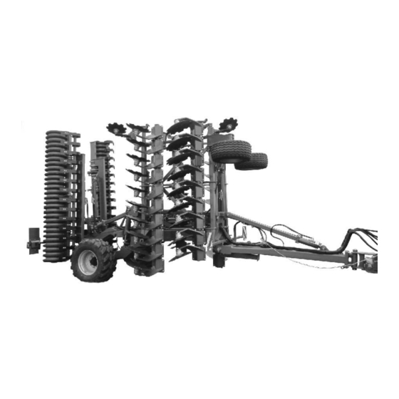
Structure and function Structure and function Function The compact disc cultivator is suitable for • shallow stubble cultivation directly after threshing • seed bed preparation in spring for maize or sugar beet • incorporation of liquid manure. The two-row disc arrangement ensures soil cultivation and rotavation. The trailing roller wheels serve to re-consolidate the soil. -
Page 41: Hydraulic Connections
Structure and function Hydraulic connections • All hydraulic hose lines are equipped with grips. Coloured markings with a code number or code letter have been applied to the gripping sections in order to assign the respective hydraulic function to the pressure line of a tractor control unit! Films are stuck on the implement for the markings that illustrate the respective hydraulic function. -
Page 42: Coupling Hydraulic Hose Lines
Structure and function WARNING Risk of infection from hydraulic fluid escaping at high pressure. When coupling/uncoupling the hydraulic hose line, ensure that the hydraulic system is not under pressure on the tractor or machine side. If you are injured by hydraulic fluid, contact a doctor immediately. 5.2.1 Coupling hydraulic hose lines WARNING... -
Page 43: Dual-Circuit Service Brake System
Structure and function Dual-circuit service brake system Compliance with the maintenance intervals is essential for the correct function of the dual-circuit service brake system. WARNING If the machine, when uncoupled from the tractor, has full com- pressed air tanks, the compressed air from the air tanks acts on the brakes and the wheels jam. -
Page 44: Coupling The Brake And Supply Lines
Structure and function (1) Air reservoir (2) Test connection (3) Drainage valve for condensate 5.3.1 Coupling the brake and supply lines WARNING Risk of contusions, cuts, dragging, catching or knocks from incorrectly functioning brake system. • When coupling the brake and supply line, ensure that: ο... -
Page 45: Uncoupling The Brake And Supply Lines
Structure and function 5.3.2 Uncoupling the brake and supply lines WARNING Risk of contusions, cuts, dragging, catching or knocks from unintentionally rolling machine with the operating brake re- leased! Always uncouple the hose coupling of the supply line (red) first fol- lowed by the hose coupling of the brake line (yellow). -
Page 46: Hydraulic Service Brake System
Structure and function Hydraulic service brake system To control the hydraulic operating brake system, the tractor requires hydraulic braking equipment. 5.4.1 Coupling the hydraulic service brake system Only couple clean hydraulic couplings. 1. Remove the protective caps. 2. Clean the hydraulic plug and socket if nec- essary. -
Page 47: Emergency Brake
Structure and function 5.4.3 Emergency brake In event of the machine being released from the tractor during travel, the emergency brake will brake the machine. (1) Pulling cable (2) Brake valve with pressure accumulator (3) Hand pump to relieve the brake (A) Brake released (B) Brake applied DANGER... -
Page 48: Parking Brake
Structure and function Parking brake When the parking brake is on, it secures the uncoupled machine against unintentional rolling. The parking brake is operated by turning the crank, which in turn operates the spindle and bowden cable. • Crank position for quick releasing / apply- ing. -
Page 49: Side Elements For Levelling
Structure and function Side elements for levelling Levelling in the boundary areas is performed using side discs or deflector guides. The working depth of the side elements can be adjusted. (1) Deflector guide (2) Side disc Certos 7001: Some of the side elements can be folded. -
Page 50: Roller
Structure and function Roller The roller assumes the depth control of the tools. • Tandem roller TW520/380 The tandem roller consists of ο the front spiral tube roller installed in the top group of holes. ο the rod roller installed in the bottom group of holes. - Page 51 Structure and function • Double U-profile roller DUW580 → Very well suited for light and medium soils. → Resistant to clogging and good load- bearing capacity. • Angle profile roller WW580 The angle profile roller is equipped with an adjustable cutting bar as an option. Raising the knife holder with increased organic matter content reduces the risk of blocking.
-
Page 52: Rear Harrow (Optional)
Structure and function 5.10 Rear harrow (optional) The rear harrow is used to crumble and level the soil. The working intensity can be adjusted by insert- ing the pins into different holes. Secure the pin with a linch pin. (1) Positioning pin for adjusting the working intensity. -
Page 53: Running Gear
Structure and function Harrow system 12-250 Hi For rollers: DUW580 Spring blade system 142 For rollers: WW580 5.11 Running gear Running gear in transport position / headlands position lowered The running gear is completely swivelled up when the implement is in operation: Certos BAG0111.10 04.18... -
Page 54: Drawbar
Structure and function 5.12 Drawbar The drawbar must be raised and lowered hydraulically using the trac- tor control unit yellow The following functions are implemented by this measure: • Lower the implement at the front into working position/lift imple- ment into headlands position •... -
Page 55: Hydraulic Drawbar Control
Structure and function 5.12.1 Hydraulic drawbar control 'Working position' Lift / lower drawbar for coupling and decoupling Lock drawbar and running gear, depressurise the hydraulic system for decoupling 5.13 Swing compensation The swing compensation reduce the pitching movements and skipping of the machine during the operation. -
Page 56: Lateral Pull Compensation
Structure and function 5.14 Lateral pull compensation The lateral pull compensation counteracts any occurring lateral pull under changing soil condi- tions. By lifting or lowering the rear of the implement, one of the two disc gangs has stronger contact with the soil and aligns the implement behind the tractor. -
Page 57: Supporting Wheels (Option)
Structure and function 5.16 Supporting wheels (option) The support wheels reduce swinging around the longitudinal axis during operation. • Support wheel, single • Support wheel, double (only for Certos 6001-2TX and 7001-2TX): Certos BAG0111.10 04.18... -
Page 58: Safety Chain For Implements Without Brake System
Structure and function 5.17 Safety chain for implements without brake system Implements without a brake system or with a single-line brake system must be equipped with a safety chain in compliance with local country regulations. The safety chain must be correctly fixed to a suitable position on the tractor before transporting. -
Page 59: Greendrill 500-H Catch Crop Seeding Unit
Structure and function 5.19 GreenDrill 500-H catch crop seeding unit The GreenDrill catch crop seeding unit enables the seeding of fine seeds and catch crops during soil cultivation. (1) Blower fan with hydraulic drive for connecting a double-acting tractor control unit (2) Foldable ascent (3) Automatic locking of the foldable ascent Also see the GreenDrill operating manual. -
Page 60: Commissioning
Commissioning Commissioning This section contains information • on operating your machine for the first time. • on checking how you may connect the machine to your tractor. • Before operating the machine for the first time the operator must have read and understood the operating manual. •... -
Page 61: Checking The Suitability Of The Tractor
Commissioning Checking the suitability of the tractor WARNING Danger of breaking during operation, insufficient stability and insufficient tractor steering and braking power in the event of improper use of the tractor! • Check the suitability of your tractor before you attach or hook up the machine. - Page 62 Commissioning 6.1.1.1 Data required for the calculation Fig. 2 [kg] Tractor empty weight See tractor operating manual or vehicle [kg] Front axle load of the empty tractor documentation [kg] Rear axle load of the empty tractor [kg] Front weight (if available) See front weight in technical data, or weigh [kg] Maximum drawbar load...
- Page 63 Commissioning 6.1.1.2 Calculation of the required minimum front ballast G of the tractor to ensure safe V min steering • − • • • Enter the numeric value for the calculated minimum ballast G V min required on the front side of the tractor, in the table (Section 6.1.1.7). 6.1.1.3 Calculation of the actual front axle load of the tractor T V tat...
- Page 64 Commissioning 6.1.1.7 Table Actual value according to Approved value ac- Double approved calculation cording to tractor load capacity (two instruction manual tyres) Minimum ballast front/rear ≤ Total weight ≤ ≤ Front axle load ≤ ≤ Rear axle load • You can find the approved values for the total tractor weight, axle loads and load capacities in the tractor registration papers.
-
Page 65: Requirements For Tractor Operation With Attached Machines
Commissioning 6.1.2 Requirements for tractor operation with attached machines WARNING Risk of breakage during operation of components through unap- proved combinations of connecting equipment! • Ensure: ο that the connection fittings on the tractor possess sufficient permissible support capability for the drawbar load actually present. - Page 66 6.1.2.1 Combination options of coupling devices The table shows the permitted combination options of coupling devic- es for the tractor and implement. Coupling device Tractor AMAZONE implement Upper hitch Pin coupling, form A, B, C Drawbar eye Socket 40 mm (ISO 5692-2) Ø...
- Page 67 Commissioning 6.1.2.2 Compare the permissible D value with actual D value WARNING Danger from breaking the coupling devices between the tractor and the implement when the tractor is not used for its intended purpose! 1. Calculate the actual D value of your combination, comprising tractor and implement.
-
Page 68: Machines Without Their Own Brake System
Commissioning Calculate the actual D value for the combination to be coupled The actual D value of a combination to be coupled is calculated as follows: T x C = g x T + C Fig. 3 permissible total weight of your tractor in [t] (See tractor operat- ing manual or vehicle documentation) axle load of the implement [t] loaded with the permissible mass without drawbar load (working load). -
Page 69: Securing The Tractor/Machine Against Unintentional Start-Up And Rolling
Commissioning Securing the tractor/machine against unintentional start-up and rolling WARNING Risk of crushing, shearing, cutting, catching, drawing in and knocks during all work on the machine • By driven work elements. • By unintentional movement of work elements or uninten- tional actuation of hydraulic functions when the tractor en- gine is running. -
Page 70: Coupling And Uncoupling The Machine
Coupling and uncoupling the machine Coupling and uncoupling the machine When coupling and uncoupling machines, follow the instructions giv- en in the section "Safety instructions for the operator" page 23. WARNING Risk of crushing, catching, drawing in and/or knocks due to un- intentional starting and rolling of the tractor when coupling or uncoupling the PTO shaft and supply lines. - Page 71 Coupling and uncoupling the machine WARNING Risk of crushing, drawing in, catching or contusions if the ma- chine unexpectedly comes away from the tractor! ο Use the intended equipment to connect the tractor and the machine in the proper way. ο...
- Page 72 Coupling and uncoupling the machine Couple the implement with draw rail on the lower link of the tractor WARNING Risk of accidents if the connection between machine and tractor separates! Always use ball sleeves with sockets and integral linch pins. 1.
-
Page 73: Uncoupling The Machine
Coupling and uncoupling the machine Couple the implement with ball bracket on the tractor ball head 1. Instruct persons to get out of the danger area between the trac- tor and the implement. 2. First couple the supply lines before coupling the implement to the tractor. - Page 74 Coupling and uncoupling the machine Uncouple the implement with draw rail 1. Safeguard tractor and implement against rolling off unintention- ally. See page 65. 2. Lower the stand. 3. Decouple the implement from the tractor. 3.1 Release the lower link. 3.2 Unlock and uncouple the lower link hooks from the tractor seat.
-
Page 75: Adjustments
Adjustments Adjustments WARNING Risk of contusions, cutting, catching, drawing in and knocks through • unintentional falling of the machine raised using the trac- tor's three-point hydraulic system. • unintentional falling of raised, unsecured machine parts. • unintentional start-up and rolling of the tractor-machine combination. -
Page 76: Working Depth Of The Side Elements
Adjustments Manual adjustment 1. Secure the tractor against unintentional starting and unintentional rolling away. 2. Adjust the intensity using the crank and secure with the linch pin. • Turning the crank towards the right: → lower intensity • Turning the crank towards the left: →... -
Page 77: Adjusting The Scraper Of The Rollers
Adjustments Adjusting the scraper of the rollers The scraper is set at the factory. To adjust the setting to the working conditions: 1. Secure the tractor and the machine against unintentional start-up and rolling 2. Release bolt under the scraper. 3. -
Page 78: Transportation
Transportation Transportation WARNING Do not exceed the maximum permissible speed. The permissible speed depends on the actual axle load of the implement, see Tech- nical Data, Seite 37. • During transportation, follow the instructions given in the section "Safety instructions for the operator", page 26. •... - Page 79 Transportation WARNING Danger of breaking during operation, insufficient stability and insufficient tractor steering and braking power on improper use of the tractor! These risks pose serious injuries or death. Observe the permissible axle and drawbar loads of the tractor. WARNING Risk of falling from the machine if riding against regulations! It is forbidden to ride on the machine and/or climb the running ma- chine.
-
Page 80: Use Of The Machine
Use of the machine Use of the machine When using the machine, observe the information in the sections • "Warning pictograms and other labels on the machine", from page 18 and • "Safety instructions for operators", from page 23 Observing this information is important for your safety. WARNING Danger of breaking during operation, insufficient stability and insufficient tractor steering and braking power on improper use... -
Page 81: Transport To Working Position
Use of the machine 10.1 Transport to working position WARNING Instruct people to leave the swivel area of the machine wing be- fore you fold the machine wing out or in. The execution of some hydraulic functions can take a little longer. Make sure that the hydraulic cylinders are able to move in and out to the limit of their stop positions. -
Page 82: Fitting Protective Tarpaulins
Use of the machine 1. Actuate the tractor control unit yellow. → Raise the implement completely. 2. Certos 7001: Put the side elements into transport position. 3. Rear harrow (optional): Before folding the implement install the transport safety bar. 4. Adjust the working depth so that the transport width of 3 m is not exceeded. -
Page 83: Certos 7001: Certos 7001: Putting The Side Elements Into Transport Position / Working Position
Use of the machine 10.1.4 Certos 7001: Certos 7001: Putting the side elements into transport position / working position Either side discs or deflector guides can be installed as side ele- ments. Side elements on the left: Side elements on the right: 1. -
Page 84: Operation
Use of the machine 10.2 Operation • Check the working position of the hydraulic drawbar control. • When carrying out work, operate the tractor control unit yellow in float position. • Adjust the tractor lower link so that the drawbar cylinder can be freely extended and retracted in float position. -
Page 85: Faults
Faults Faults Different working depths across the working width? → Synchronise the hydraulic cylinders! For a uniform working depth across the entire implement width, the corresponding hydraulic cylinders must have the same length. If this is not the case, the hydraulic cylinders can be synchronised: 1. -
Page 86: Cleaning, Maintenance And Repairs
Cleaning, maintenance and repairs Cleaning, maintenance and repairs WARNING Risk of contusions, cutting, catching, drawing in and knocks through ο unintentional falling of the machine raised using the tractor's three-point hydraulic system. ο unintentional falling of raised, unsecured machine parts. ο... -
Page 87: Cleaning
Cleaning, maintenance and repairs 12.1 Cleaning • Pay particular attention to the brake, air and hydraulic hoses! • Never treat brake, air and hydraulic hoses with petrol, benzene, petroleum or mineral oils. • After cleaning, grease the machine, in particular after cleaning with a high pressure cleaner/steam jet or liposoluble agents. -
Page 88: Lubrication Instructions
Cleaning, maintenance and repairs 12.2 Lubrication instructions Lubrication points on the machine are indicated with the foil. Carefully clean the lubrication points and grease gun before lubrication so that no dirt is pressed into the bearings. Press the dirty grease out of the bearings completely and replace it with new grease. - Page 89 Cleaning, maintenance and repairs Certos BAG0111.10 04.18...
-
Page 90: Maintenance Plan - Overview
Cleaning, maintenance and repairs 12.3 Maintenance plan - overview • Carry out maintenance work when the first interval is reached. • The times, running hours or maintenance intervals of any third party documentation shall have priority. After the first working run Component Servicing work Workshop work... - Page 91 Cleaning, maintenance and repairs Every three months / 200 operating hours Component Servicing work See page Workshop work • Brake system Check according to the inspection instructions • Clean the line filters • Brake pad check • Adjustment of the slack adjuster •...
-
Page 92: Axle (Running Gear / Support Wheel) And Brake
Cleaning, maintenance and repairs 12.4 Axle (running gear / support wheel) and brake For optimum brake performance with a minimum of wear, we recom- mend that the brakes on the tractor are balanced with those on the machine. After the service braking system has been run in for a suita- ble period, arrange for the brakes to be balanced by a specialist workshop. - Page 93 Cleaning, maintenance and repairs Checking the brake drum for dirt 1. Unscrew the two cover plates (1) on the inside of the brake drum. 2. Remove any dirt and plant debris which may have entered the drum. 3. Refit the cover plates. CAUTION Dirt entering the drums may be deposited on the brake pads (2) and...
- Page 94 Cleaning, maintenance and repairs Brake pad check Open the inspection hole (1) by pulling out the rubber stopper (if present). At a residual thickness for riveted pads 5 mm (N 2504) 3 mm for adhesive pads 2 mm the brake pad must be replaced. Reinsert the rubber tab.
- Page 95 Cleaning, maintenance and repairs Checking the function of the automatic linkage adjuster 1. Remove the rubber stopper cap. 2. Slacken the adjusting screw (arrow) with a ring spanner approx. ¾ of a turn anti- clockwise. There must be a free travel of at least 50 mm for a lever length of 150 mm.
- Page 96 Cleaning, maintenance and repairs Cleaning the line filter Perform work in an unpressurized state. Secure the implement against rolling away. 1. Remove the bolt locking compound by hammering and remove the bolts (1). 2. Unscrew the bolts (2) by a few turns. 3.
-
Page 97: Inspection Instructions For The Dual-Circuit Service Brake System
Cleaning, maintenance and repairs 12.4.1 Inspection instructions for the dual-circuit service brake system Leak tightness check 1. Check all connections, pipe lines, hose lines and screw connec- tions for leak tightness. 2. Remedy leakages. 3. Repair any areas of chafing on pipes and hoses. 4. -
Page 98: Hydraulic Brakes
Cleaning, maintenance and repairs 12.4.2 Hydraulic brakes Check of the hydraulic brake • Check all brake hoses for wear • check all screw unions for seal tightness • renew any worn or damaged parts. Venting the brake system (workshop work) After each brake repair, for which the system has been opened, bleed the brake system, because air may have entered the pressure hoses. -
Page 99: Check The Coupling Device
Cleaning, maintenance and repairs 12.6 Check the coupling device DANGER! • Replace a damaged drawbar with a new one immediately - for road traffic safety reasons. • Repairs may only be carried out by the manufacturer facto- • For safety reasons, it is forbidden to weld on and drill holes in the drawbar. -
Page 100: Parking Brake
Cleaning, maintenance and repairs 12.7 Parking brake On new machines, the brake cables of the parking brake may stretch. Readjust the parking brake, • if three quarters of the spindle tensioning distance is required to firmly apply the parking brake. •... -
Page 101: Tyres / Wheels
Cleaning, maintenance and repairs 12.8 Tyres / wheels • Check the running gear tyres regularly for damage and firm seat- ing on the wheel rim. • Required tyre pressure: ο Running gear tyre: 550/45 R22.5 LI159A8 2,8 bar 4,3 bar 400/60 R22.5 LI160A8 620/40 R22.5 LI164A8 4,0 bar... -
Page 102: Fitting Tyres (Workshop Work)
Cleaning, maintenance and repairs 12.8.2 Fitting tyres (workshop work) • Remove any outbreaks of corrosion from the wheel rim seating surfaces before fitting a new / another tyre. Corrosion can cause damage to the wheel rims when the vehicle is in operation. •... -
Page 103: Hydraulic System (Workshop Work)
• Replace the hydraulic hose line if it is damaged or worn. Only use AMAZONE original hydraulic hose lines. • The hydraulic hose lines should not be used for longer than six years, including any storage time of maximum two years. Even... -
Page 104: 12.10.1 Labelling Hydraulic Hose Lines
Cleaning, maintenance and repairs 12.10.1 Labelling hydraulic hose lines The assembly labelling provides the follow- ing information: (1) Manufacturer's marking on the hydraulic hose line (A1HF) (2) Date of manufacture of hydraulic hose line (04/02 = year/month = February 2004) (3) Maximum approved operating pressure (210 BAR). -
Page 105: 12.10.4 Installation And Removal Of Hydraulic Hose Lines
12.10.4 Installation and removal of hydraulic hose lines When installing and removing hydraulic hose lines, always observe the following information: • Only use AMAZONE original hydraulic hose lines. • Ensure cleanliness. • You must always install the hydraulic lines so that, in all states of operation: ο... -
Page 106: Hydraulic Circuit Diagram
12.12 Hydraulic circuit diagram Certos 4001- / 5001-2TX Certos BAG0111.10 04.18... - Page 107 Cleaning, maintenance and repairs Certos 6001- / 7001-2TX Certos BAG0111.10 04.18...
- Page 108 Crushboard Certos 4001- / 5001-2TX Crushboard Certos 6001- / 7001-2TX Certos BAG0111.10 04.18...
-
Page 109: Screw Tightening Torques
Cleaning, maintenance and repairs 12.13 Screw tightening torques 10.9 12.9 M 8x1 M 10 16 (17) M 10x1 M 12 18 (19) M 12x1,5 M 14 M 14x1,5 M 16 M 16x1,5 M 18 M 18x1,5 M 20 M 20x1,5 M 22 M 22x1,5 1050...
Need help?
Do you have a question about the Certos 4001-2TX and is the answer not in the manual?
Questions and answers