Table of Contents
Advertisement
Quick Links
Advertisement
Table of Contents

Subscribe to Our Youtube Channel
Related Manuals for Amazone Centaya 3000 Super 1600


Summary of Contents for Amazone Centaya 3000 Super 1600
- Page 1 Operating manual Pneumatic pack top seed drill Centaya 3000/3500/4000 Super 1600 Centaya 3000/3500/4000 Super 2000 Please read and observe this operating manual before initial MG6194 operation of the implement! BAH0092-3 01.19 Keep it in a safe place for future use!
- Page 2 Reading the instruction manual and to adhere to it should not appear to be inconvenient and superfluous as it is not enough to hear from others and to realise that a machine is good, to buy it and to believe that now everything would work by itself.
- Page 3 + 49 (0) 5405 50 1-0 Email: amazone@amazone.de Spare parts order Spare parts lists are freely accessible in the spare parts portal at www.amazone.de. Please send orders to your AMAZONE dealer. Formalities of the operating manual Type: Centaya Super Document number: MG6194 Compilation date: 01.19...
- Page 4 Foreword Dear Customer, You have chosen one of the quality products from the wide product range of AMAZONEN-WERKE, H. DREYER GmbH & Co. KG. We thank you for your trust in our products On receiving the implement, check to see if it has been damaged during transport or if parts are miss- ing.
-
Page 5: Table Of Contents
Loading and unloading the implement upon delivery ......36 Product description ................... 39 Components of the AMAZONE seeding combination ............39 Equipment variations of the Centaya pneumatic pack top seed drill ........40 ... - Page 6 User information AMAZONE calibration button ....................59 Control terminal for implements with ISOBUS system ............59 5.3.1 AMAZONE AmaTron 4 control terminal ................60 5.3.2 AMAZONE TwinTerminal ...................... 60 Implement documentation ..................... 61 ...
- Page 7 User information 6.1.1.7 Table ............................ 112 Secure the tractor / implement against unintentional starting and rolling away ....113 Hydraulic connection for the blower fan drive ..............114 Coupling and uncoupling the implement ..........115 ...
- Page 8 User information 8.11.4 Move the tramline marker to working position with exact following harrow bracket ..174 8.12 Moving the exact following harrow road safety bar into road transport/parking position ..........................175 8.12.1 Moving the road safety bar into road transport position ............175 ...
- Page 9 User information 12.7.8 Checking / replacing the TwinTeC press roller ..............219 12.7.9 Checking / readjusting / replacing the TwinTeC roller scraper ..........220 12.8 Bolt tightening torques ......................221 Hydraulic diagram ..................224 ...
-
Page 10: User Information
User information User information The User Information section provides information on use of the operating manual. This operating manual is valid for all versions of the implement. Figures serve as a reference and are to be understood as representations of the principle. All of the equipment is described without indicating it as special optional equipment. - Page 11 User information Lists Lists without an essential order are shown as a list with bullets. Ex- ample: Point 1 Point 2 Item numbers in diagrams Numbers in round brackets refer to the item numbers in the diagrams. The first number refers to the diagram and the second number to the item.
-
Page 12: General Safety Instructions
General safety instructions General safety instructions This section contains important information on safe operation of the implement. Obligations and liability Comply with the instructions in the operating manual Knowledge of the basic safety information and safety regulations is a basic requirement for safe handling and fault-free implement opera- tion. - Page 13 General safety instructions Risks in handling the implement The implement has been constructed to the state-of-the art and the recognised rules of safety. However, operating the implement may cause risks and restrictions the health and safety of the user or third persons ...
-
Page 14: Representation Of Safety Symbols
General safety instructions Representation of safety symbols Safety instructions are indicated by the triangular safety symbol and the highlighted signal word. The signal word (DANGER, WARNING, CAUTION) describes the severity of the risk, and carries the following meaning: DANGER Indicates a direct threat at high risk which will result in death or most serious bodily harm (loss of limbs or long-term harm), should it not be prevented. -
Page 15: Organisational Measures
General safety instructions Organisational measures The operator must provide the necessary personal protective equip- ment as per the information provided by the manufacturer of the crop protection agent to be used, such as: Safety glasses Protective shoes Chemical-resistant overalls ... -
Page 16: User Training
General safety instructions User training Only those people who have been trained and instructed may work with/on the implement. The opera- tor must clearly specify the responsibilities of the people charged with operation and maintenance work. People being trained may only work with/on the implement under the supervision of an experienced person. -
Page 17: Safety Measures In Normal Operation
General safety instructions Safety measures in normal operation Only operate the implement if all the safety and protection equipment is fully functional. Check the implement at least once a day for visible damage and check the function of the safety and protection equipment. Danger from residual energy Note that there may be residual mechanical, hydraulic, pneumatic and electrical/electronic energy on the implement. -
Page 18: Design Changes
General safety instructions 2.10 Design changes You may make no changes, expansions or modifications to the im- plement without the authorisation of AMAZONEN-WERKE. This also applies when welding support parts. Any extension or conversion work shall require the written approval of AMAZONEN-WERKE. -
Page 19: Spare And Wear Parts And Aids
Immediately replace any implement parts which are not in a perfect state. Use only genuine AMAZONE spare and wear parts or the parts cleared by AMAZONEN-WERKE so that the operating permit retains its validity in accordance with national and international regulations. If... -
Page 20: Warning Symbols And Other Labels On The Implement
Warning symbols and other labels on the implement Always keep all the warning symbols of the implement clean and in a legible state! Replace illegible warning symbols. You can request the warning symbols from your AMAZONE dealer using the order number (e.g., MD 075). Structure Warning symbols indicate danger areas on the implement and warn against residual dangers. - Page 21 General safety instructions MD 078 Risk of crushing of fingers/hand by accessi- ble, moving parts of the implement! This hazard can cause the most severe injuries with loss of body parts. Never reach into the danger area when the trac- tor engine is running with the universal joint shaft or hydraulic / electronic system connected.
- Page 22 General safety instructions MD 095 Before commissioning the implement read and observe the operating manual and the safety in- structions carefully! MD 096 Danger from escaping high-pressure hydrau- lic fluid due to leaking hydraulic hose lines! This danger may cause serious injuries, perhaps even resulting in death, if escaping high-pressure hydraulic fluid passes through the skin and into the body.
- Page 23 General safety instructions MD 102 Danger from intervention in the implement, e.g. installation, adjusting, troubleshooting, cleaning, maintaining and repairing, due to the tractor and the implement being started unintentionally and rolling away! These dangers can cause extremely serious and potentially fatal injuries. ...
-
Page 24: Position Of Warning Symbols
General safety instructions MD 157 The stability of the solo implement is guaran- teed only if the empty implement is support- ed on the parking supports. Always set the empty implement down so that it is stable, on a horizontal parking area with a firm base. - Page 25 General safety instructions Fig. 2 Fig. 3 Fig. 4 Centaya Super BAH0092-3 01.19...
-
Page 26: Dangers In Case Of Non-Compliance With The Safety Instructions
General safety instructions 2.14 Dangers in case of non-compliance with the safety instructions Non-compliance with the safety information can pose both a danger to people and to the environment and implement can lead to the loss of all warranty claims. In particular, non-compliance with the safety information could pose the following risks: ... -
Page 27: Safety Information For Users
General safety instructions 2.16 Safety information for users WARNING Risk of crushing, cutting, being trapped or drawn in, or impact through inadequate roadworthiness and operational safety. Before starting up the implement and the tractor each time, always check their traffic and operational safety. CAUTION Before adjustment, maintenance and repair work ... -
Page 28: General Safety Instructions And Accident Prevention Instructions
General safety instructions 2.16.1 General safety instructions and accident prevention instructions In addition to these instructions, also comply with the generally valid national and safety and accident prevention regulations. The warning symbols attached on the implement provide im- portant instructions for safe operation of the implement. - Page 29 General safety instructions Coupling and uncoupling the implement Only connect and transport the implement with tractors suitable for the task. When coupling implements to the tractor's 3-point hydraulic sys- tem, the mounting categories of the tractor and the implement must always be compatible.
- Page 30 General safety instructions Use of the implement Before starting work, make sure that you understand all the equipment and control elements of the implement and their func- tions. It is too late for this when the implement is already in oper- ation.
- Page 31 General safety instructions Always properly fasten the front or rear weights to the intended fastening points. Comply with the maximum payload of the mounted/towed im- plement and the permissible axle and drawbar loads of the trac- tor. The tractor must guarantee the prescribed brake delay for the loaded vehicle combination (tractor plus mounted/towed imple- ment).
-
Page 32: Hydraulic System
Replace the hydraulic hose lines if they are damaged or worn. Use only original AMAZONE hydraulic hose lines. The hydraulic hose lines should not be used for longer than six years, including any storage time of maximum two years. Even... - Page 33 General safety instructions Always place the appropriate cover over the positive battery ter- minal. If there is accidental earth contact, there is a danger of explosion. Risk of explosion. Avoid sparking and naked flames in the area of the battery. ...
-
Page 34: Mounted Implements
General safety instructions 2.16.4 Mounted implements When mounting, the mounting categories on tractor and imple- ment must be compatible or an adapter must be used. Observe the manufacturer's instructions. Before mounting or dismounting implements on the 3-point hitch, put the operating equipment to a position in which accidental raising or lowering is impossible. -
Page 35: Operation Of The Seed Drill
Spare parts must at least comply with the specified technical re- quirements of AMAZONEN-WERKE. This is ensured through the use of genuine AMAZONE spare parts. Centaya Super BAH0092-3 01.19... -
Page 36: Loading And Unloading The Implement Upon Delivery
Loading and unloading the implement upon delivery Loading and unloading the implement upon delivery The pictogram marks the location at which the slings for lifting the implement with a crane is to be secured. DANGER Attach the slings for loading the im- plement with a crane only at the marked locations. - Page 37 Loading and unloading the implement upon delivery Fasten the 2 slings on the marked fastening points (Fig. 7/1) on the pack top seed drill Fig. 7 1 sling to the transport eye (Fig. 8/1) in the seed hopper. Secure the combination properly on the transport vehicle.
- Page 38 Loading and unloading the implement upon delivery Following transport – dissembling the transport eye 1. After unloading the combination from the transport vehicle, remove the transport eyes (Fig. 9/1). 1.2 Loosen the 2 round-head screws (Fig. 9/2) and remove the transport eye. Fig.
-
Page 39: Product Description
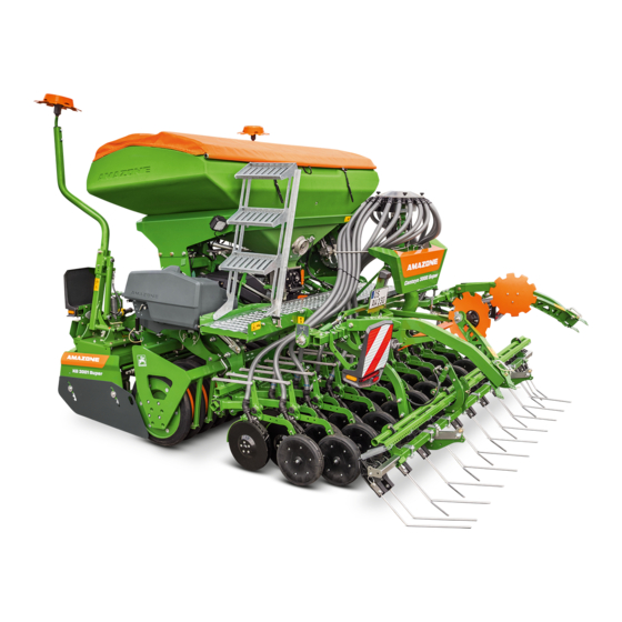
Product description Product description Components of the AMAZONE seeding combination Fig. 13 (1) AMAZONE soil tillage implement (2) AMAZONE roller (3) AMAZONE pneumatic pack top seed drill Centaya Super Centaya Super BAH0092-3 01.19... -
Page 40: Equipment Variations Of The Centaya Pneumatic Pack Top Seed Drill
Product description Equipment variations of the Centaya pneumatic pack top seed drill Fig. 14 Centaya 3500 Super equipped with RoTeC-Pro Control coulters Fig. 15 Centaya 3000 Super equipped with TwinTeC double disc coulters Centaya Super BAH0092-3 01.19... - Page 41 Product description Fig. 16 CombiDisc 3000 with Centaya 3000 Super and TwinTeC double disc coulters Centaya Super BAH0092-3 01.19...
-
Page 42: Components Of The Centaya Pneumatic Pack Top Seed Drill
Product description Components of the Centaya pneumatic pack top seed drill Fig. 17 (1) Seed hopper with roller tarpaulin (8) TwinTeC double disc coulter, optionally RoTeC-Pro Control coulter (2) Loading board with steps (9) Tramline marker (3) Control centre (10) Exact following harrow, (4) Seed metering unit, electrically driven (5) Distributor head (11) Track marker, installed... - Page 43 Product description (1) Seed metering unit, electrically driven (2) Injector sluice Fig. 18 (1) Blower fan (2) Hydraulic motor Fig. 19 Cabinet for the supply lines Fig. 20 Centaya Super BAH0092-3 01.19...
-
Page 44: Safety And Protective Equipment
Product description Safety and protective equipment (1) 2 bars serve as a mechanical transport lock for the track markers on the soil tillage im- plement, see also "Soil tillage implement" operating manual. Fig. 21 (1) Handrail Fig. 22 (1) Charging sieve in the seed hopper. Prevents contact with the rotating metering roller. -
Page 45: Overview - Supply Cable / Hydraulic Hose Lines
Product description Overview – Supply cable / hydraulic hose lines 4.5.1 Supply cable Designation Function Implement plug Data transfer implement/job computer/control terminal Plug (7-pin) Connection to the lighting system for road travel 4.5.2 Identification of the hydraulic hose lines All hydraulic hose lines have handles with col- oured markings and a code number or code let- ter to assign the respective hydraulic function to the pressure line of a tractor control unit. -
Page 46: Connection And Function Of The Tractor Control Units
Product description 4.5.4 Connection and function of the tractor control units Required Identification of the configuration of the Function when actuating the tractor control unit hydraulic hose lines tractor control unit Track marker Lifting and lowering, alternating Single yellow acting Tramline marker Lifting and lowering, depending on the tramline counter... -
Page 47: Comfort Hydraulic System - Implements With Isobus System
Product description 4.5.5 Comfort hydraulic system - Implements with ISOBUS system Required Identification of the configuration of the Function when actuating the tractor control unit hydraulic hose lines tractor control unit Track marker Lifting and lowering, alternating Single yellow Tramline marker acting Lifting and lowering, depending on the tramline counter... -
Page 48: Traffic Safety Equipment
Product description Traffic safety equipment (1) 2 rear-facing warning signs, left and right. Not illustrated: 2 warning signs directed to the side (not permitted in Germany and in many other countries). only implements with exact following harrow: (2) Road safety bar, two-part Fig. -
Page 49: Intended Use
is mounted on an AMAZONE soil tillage implement with roller approved for this purpose is coupled to the tractor three-point hitch together with the soil tillage implement and is operated by one person. -
Page 50: Approved Amazone Implement Combinations
4.7.1 Approved AMAZONE implement combinations The pneumatic Centaya Super pack top seed drill may only be combined with the following AMAZONE implements listed in the table. Combining a Centaya Super with other implements is considered improper use and is therefore for- bidden. -
Page 51: Danger Areas And Danger Points
Product description Danger areas and danger points The danger area is the area around the implement in which people can be caught: by work movements made by the implement and its tools by materials or foreign bodies thrown out of the implement ... -
Page 52: Rating Plate And Ce Mark
Product description Rating plate and CE mark The figure shows the arrangement of the rating plate and the CE mark on the implement. The CE mark indicates compliance with the stipulations of the valid EU directives. Fig. 30 The following information is specified on the rat- ing plate and the CE mark: (1) Implement ID no. -
Page 53: Technical Data
Product description 4.10 Technical data Centaya 3000 Super 1600 Centaya 3500 Super 1600 Centaya 4000 Super 1600 Hopper volume 1600 1600 1600 Centaya 3000 Super 2000 Centaya 3500 Super 2000 Centaya 4000 Super 2000 Hopper volume 2000 2000 2000 Centaya... -
Page 54: Technical Data For Calculating The Tractor Weight And The Tractor Axle Loads
Product description 4.11.1 Technical data for calculating the tractor weight and the tractor axle loads The technical data [total weight (G ) and dis- tance (d)] is needed to calculate the tractor weights and tractor axle loads, see page 109. The permissible total weight (GH) of the rear- mounted implement combination is obtained from the sum of the weights listed in the following... -
Page 55: Required Tractor Equipment
4.12 Required tractor equipment For operation of the implement in compliance with the intended use, the tractor must fulfil the following requirements. AMAZONE rotary cultivator, KW wedge ring roller and starting at 81 kW (110 bhp) Centaya 3000 Super with... -
Page 56: Layout And Function
The Centaya can be equipped with a choice of RoTeC-Pro Control coulters or TwinTeC double disc coulters (Fig. 33/2). The seed falls into the seed furrow prepared by the coulters. In combination with the AMAZONE rotary cultivator or the CombiDisc compact disc harrow, mulch seeding is possible with both coulter types. - Page 57 Layout and function The roller serves to reconsolidate the soil. AMAZONE provides the suitable roller for any seed type and any soil. The Centaya Super may only be combined with the approved AMAZONE rollers, see chapter "Approved AMAZONE implement combinations", page 50.
- Page 58 Layout and function The AMAZONE KWM wedge ring roller with ma- trix tyre profile is characterised by two particular- ly good features. The wedge ring roller with ma- trix tyre profile has particularly good self- propulsion and produces lots of fine soil to fill the seed rows.
-
Page 59: Amazone Amadrill 2 Control Terminal
The ISOBUS system makes it possible to connect the implement to any ISOBUS control terminal. If the tractor has an ISOBUS system, the AMAZONE job computer can be connected to the existing ISOBUS socket of the tractor and operated with the on-board terminal. -
Page 60: Amazone Amatron 4 Control Terminal
Layout and function 5.3.1 AMAZONE AmaTron 4 control terminal As an option, the combination can be delivered e.g. with the AMAZONE AmaTron 4 control ter- minal. The AmaTron 4 control terminal (Fig. 40) can operate all implements that are equipped with the ISOBUS system. -
Page 61: Implement Documentation
Layout and function Implement documentation The implement documentation and the operating manual can be found in the case (Fig. 42/1) un- der the seed hopper. Keep all operating manuals or a copy in the case on your implement to avoid operating errors. -
Page 62: Radar Device
Layout and function Radar device The implement has a radar device (Fig. 45/1). The radar device is switched on automatically when a speed is detected. Provided that the con- trol terminal is ready for operation and the com- bination is in working position. Fig. -
Page 63: Seed Hopper And Loading Board
Layout and function Seed hopper and loading board The roller tarpaulin (Fig. 46/1) protects the con- tents of the seed hopper from water and dust. The seed hopper is filled from the loading board, on the back of the seed drill. Fig. -
Page 64: Fill Level Monitoring
Layout and function 5.5.1 Fill level monitoring A low level sensor (Fig. 49/1) monitors the seed level in the seed hopper. If the seed level reaches the low level sensor, an acoustic signal is emitted. At the same time, the control terminal displays a warning message. -
Page 65: Metering
Layout and function Metering The seed is metered by a metering roller in the metering unit. The metering roller can be re- placed. Fig. 50 An electric motor (Fig. 51/1) drives the metering roller (full metering). The metered seed falls into a sluice (Fig. 51/2) and is directed by the air flow to the distributor head and then to the coulters. - Page 66 Layout and function The metering roller selection is dependent on the grain size seed rate. A selection of metering rollers with different volumes is available. The selected metering roller volume ) should not be too large but still sufficient to spread the required quantity (kg/ha). The required metering roller depending on the seed and the seed rate can be found in the table (chap- ter "Table –...
-
Page 67: Metering Roller Diagram Table - Figures
Layout and function 5.6.1 Metering roller diagram table - figures Metering roller Volume: ....7.5 cm Metering roller Volume: ....20 cm Metering roller Volume: ....40 cm Centaya Super BAH0092-3 01.19... - Page 68 Layout and function Metering roller Volume: ....120 cm Metering roller Volume: ....210 cm Metering roller Volume: ....350 cm Centaya Super BAH0092-3 01.19...
- Page 69 Layout and function Metering roller Volume: ....600 cm Metering roller Volume: ....660 cm Metering roller Volume: ....880 cm Centaya Super BAH0092-3 01.19...
- Page 70 Layout and function 5.6.2 Table – metering rollers, seed Metering rollers 7,5 cm³ 20 cm³ 40 cm³ 120 cm³ 210 cm³ Seed Beans Buckwheat Spelt Peas Flax (dressed) Barley Grass seed Oats Millet Caraway Lupins Alfalfa Maize Poppy Oilseed (moist dressing) Fodder radish Phacelia Rapeseed...
- Page 71 Layout and function Metering rollers 350 cm³ 600 cm³ 660 cm³ 880 cm³ Seed Beans Buckwheat Spelt Peas Flax (dressed) Barley Grass seed Oats Millet Caraway Lupins Alfalfa Maize Poppy Oilseed (moist dressing) Fodder radish Phacelia Rapeseed Red clover Mustard Sunflowers Turnips Triticale...
-
Page 72: Calibrating The Seed Rate
Layout and function 5.6.3 Calibrating the seed rate When calibrating the seed rate, the later field pass is simulated. The metering roller speed required to spread the desired seed rate is calculated [kg/ha]. The metering roller speed is calculated from the simulated area (e.g. 1/40 ha) and the weight [kg] of the collected material. - Page 73 Layout and function The calibration is started by pressing the button on the control termi- nal in the tractor cab or by pressing the calibration button (Fig. 55/1) Fig. 55 by pressing the button on the TwinTerminal (Fig.
- Page 74 Layout and function The scale (Fig. 58/1) is inserted, together with the collapsible bucket (Fig. 58/2), in the control centre. Fig. 58 The folding bracket (Fig. 59/1) is used to hang up the digital scale (Fig. 59/2). Fig. 59 Centaya Super BAH0092-3 01.19...
-
Page 75: Blower Fan
Layout and function Blower fan The blower fan (Fig. 60/1) generates the air cur- rent that carries the seed to the seeding coulters. The hydraulic motor (Fig. 60/2) drives the blower fan. The control terminal displays the current fan speed and issues an alarm if there is a deviation from the nominal speed. - Page 76 Layout and function Fig. 63 The blower fan speed determines the air volume of the air current. The higher the blower fan speed, the greater is the air volume generated. The required blower fan speed (Fig. 63/1) depends on the seed ...
-
Page 77: Distributor Head
Layout and function Distributor head The distributor head serves to distribute the metered material evenly over all of the coulters. For this purpose, the distributor head has indi- vidual segments. The metered material is evenly distributed over all of the segments in the distrib- utor head, and is carried to the coulters through the connected seed line tubes. -
Page 78: Seed Tube Monitoring
Layout and function 5.8.1 Seed tube monitoring The seed tube hoses represent the connection between the distributor head and the coulters. Each seed tube hose can be equipped with a sensor (Fig. 66/1) that detects the seed flow. A warning message is issued when the seed flow in a monitored seed line hose is interrupted or large deviations occur in the flow rate between the monitored seed line hoses. -
Page 79: Spreading Seed With Wide Row Spacing
Layout and function Spreading seed with wide row spacing For spreading seed with wide row spacing, e.g. maize, individual seed rows can be closed. The seed flow is interrupted to the coulters that are not required. The seed lines in the distributor head are closed with the plugs (Fig. -
Page 80: Rotec-Pro Control Coulter
Layout and function 5.10 RoTeC-Pro Control coulter The RoTeC-Pro Control coulter (Fig. 68/1) is used for seed placement on ploughed or mulched soil, even with large quantities of straw and plant residues. Thanks to the support of the coulter on the depth control disc / wheel (Fig. - Page 81 Layout and function The adjust the seed placement depth, the depth control disc/wheel (see Fig. 71) can be engaged in 4 holes on the coulter removed if the seed placement depth is not reached. Hole Placement Shallow Seeding without depth control disc / Deep depth control wheel...
-
Page 82: Twintec Double Disc Coulter
Layout and function 5.11 TwinTeC double disc coulter The TwinTeC double disc coulter (Fig. 73/1) is used for plough seeding and mulch seeding. Harvest residues are cut by the large double disc coulters, clearing the plant residues evenly to the side and forming a clean seed furrow. - Page 83 Layout and function The seed placement depth depends on the factors Soil type (light to heavy) Forward speed Set seed placement depth Set coulter pressure. The placement depth and the coulter pressure can be adjusted independently from one another. The coulter pressure can reach 60 kg per coulter.
-
Page 84: Seed Placement Depth (Twintec)
Layout and function 5.11.1 Seed placement depth (TwinTeC) Implements with TwinTeC double disc coulters The seed placement depth is adjusted with the central key. Fig. 75 Turn clockwise (+): deeper placement Turn counter- clockwise (-): shallower placement The scale (Fig. 76/1) displays the set working depth in percent. -
Page 85: Coulter Pressure, Seed Rate Increase And Coulter Lift (All Coulter Types - Hydraulically Actuated)
Layout and function 5.12 Coulter pressure, seed rate increase and coulter lift (all coulter types - hydraulically actuated) Adaptation of the coulter pressure to the soil is required to achieve uniform seed placement depth on different soils. The hydraulically actuated coulter pressure adjustment allows the coulter pressure to be adapted to the soil during operation, when changing to heavy soil. -
Page 86: 5.12.1.2 Activating The Seed Rate Increase
Layout and function 5.12.1.2 Activating the seed rate increase Implements with RoTeC-Pro control coulters and TwinTeC double disc coulters The seed rate can be increased on heavy soils for a uniform crop. The control terminal serves to enter the desired rate increase. -
Page 87: 5.12.1.3 Coulter Lift
Layout and function 5.12.1.3 Coulter lift Implements with RoTeC-Pro control coulters and TwinTeC double disc coulters For soil tillage without seeding, the coulters can be lifted out of the soil. Fig. 80 The tractor control valve (green) is used to actu- ate the coulter lift. -
Page 88: Exact Following Harrow
Layout and function 5.13 Exact following harrow The exact following harrow (Fig. 83/1) evenly co- vers the seeds deposited in the seed furrows with loose earth and smoothes the ground. The following are adjustable the exact following harrow tine setting ... -
Page 89: Exact Following Harrow Tine Position
Layout and function 5.13.1 Exact following harrow tine position Exact following harrow tine position Distance "A" = 230 to 280 mm When correctly set, the harrow tines of the ex- act following harrow should: lie horizontally on the ground and ... -
Page 90: Exact Following Harrow Pressure
Layout and function 5.13.2 Exact following harrow pressure The exact following harrow pressure must be adjusted depending on the soil. To achieve uniform cov- erage of the seed row with soil, the exact following harrow pressure must be set higher on heavy soil than on light soil. -
Page 91: Seeding Without Exact Following Harrow (Exact Following Harrow Lift)
Layout and function 5.13.3 Seeding without exact following harrow (exact following harrow lift) The exact following harrow can be lifted inde- pendently of the position of the coulters. A hydraulic cylinder (Fig. 90/1) lifts the exact fol- lowing harrow. Depending on the implement equipment, actua- tion of the exact following harrow lift with a trac- tor control unit is possible in 2 variations. -
Page 92: Seed Pre-Metering
Layout and function 5.14 Seed pre-metering Seed pre-metering, which meters the seeds in the air current before the implement starts up, can be switched on in the ISOBUS control terminal. Seed pre-metering is used when corners are to be seeded that can only be reached when the imple- ment is being reversed or with raised coulters. -
Page 93: Tramlines
Layout and function 5.16 Tramlines Tramlines can be created on the field. Tramlines are seed-free tracks for fertilising and plant care implement used later. The tramline can also be created as an interval tramline. In doing so, the tramline is seeded in recurring freely selectable intervals. - Page 94 Layout and function Fig. 94 With tramline control, tramlines (A) can be created on the field. When creating a tramline, a display appears on the control terminal. The adjustable tramline spacing (b) corresponds to the working width of the cultivating implement (B), e.g.
- Page 95 Layout and function Only implements with ISOBUS system: The following data is entered on the control ter- minal: Track width (Fig. 95/a) of the cultivating tractor Fig. 95 Wheelmark width (Fig. 96/c) of the cultivat- ing tractor Distance from the plant row to the track (Fig.
-
Page 96: Tramline Rhythm, Tabular Determination
Layout and function 5.16.1 Tramline rhythm, tabular determination Read the required tramline rhythm from the table. The tramline rhythm is derived from the required tramline spacing and the working width of the seed drill. Other tramline rhythms can be found in the control terminal. - Page 97 Layout and function Fig. 98 Centaya Super BAH0092-3 01.19...
-
Page 98: One-Sided Switching
Layout and function 5.16.3 One-sided switching Fig. 99 During the first field pass, it may be necessary to operate the seed drill with half the working width (part-width section). The coulter on the left side of the implement (see Fig. 99) does not place seeds in the soil, when field work begins on the right field edge. -
Page 99: 5.16.3.2 One-Sided Switching By Actuating A Lever
Layout and function 5.16.3.2 One-sided switching by actuating a lever The distributor head can have two partition walls (Fig. 101/1), which are embedded in the floor of the distributor head. The partition walls interrupt the seed supply to the right or left half of the im- plement respectively. -
Page 100: 5.16.3.3 One-Sided Switching By Pressing A Button On The Control Terminal
Layout and function 5.16.3.3 One-sided switching by pressing a button on the control terminal The distributor head can have two partition walls (Fig. 104/1), which are embedded in the floor of the distributor head. The partition walls interrupt the seed supply to the right or left half of the implement respectively. -
Page 101: Tramline Marker
Layout and function 5.17 Tramline marker The tramline marker has two track discs, which lower automatically when the tramlines are created. The track discs mark the tramline that has just been created. This makes the tramlines visible before the seed has germinated. The track discs are raised if no tramline is created. -
Page 102: Tramline Marker With Bracket On The Exact Following Harrow
Layout and function 5.17.2 Tramline marker with bracket on the exact following harrow The brackets for the track discs (Fig. 109/1) are secured to the exact following harrow. The following can be adjusted: the spacing of the track discs relative to each other, to mark the tractor wheelmark width ... -
Page 103: Track Marker
Layout and function 5.18 Track marker Fig. 112 The hydraulically-actuated track markers dig into the ground alternately on the left and the right of the implement. In doing so, the active track marker (Fig. 112/1) creates a track on the field. When the track markers are properly adjusted, the next row is automatically connected when the trac- tor driver passes over the centre of the created track. -
Page 104: Camera System
Layout and function When transporting the implement and turning at the end of the field, both track markers (Fig. 113/1) must be raised. During transport, each track marker must be secured with a bar. For a more detailed description, refer to the "Soil tillage implement"... -
Page 105: Headlight
Layout and function 5.20 Headlight The floodlights allow visibility of the implement tools and the worked area when working after dark. Fig. 115 In the metering area, there is a light (Fig. 116/1) that is switched on and off together with the floodlights (see above). -
Page 106: Greendrill 200E
Layout and function 5.21 GreenDrill 200E Fig. 117 In addition to seeding, the spreading of nurse crops, catch crops and re-seeding grass is possible. As an option, the GreenDrill 200E catch crop seed drill (Fig. 117/1) is mounted at the rear of the implement. -
Page 107: Start-Up
Start-up Start-up This section contains information on initial operation of your implement on how to check if you may mount the implement onto your tractor. Before operating the implement for the first time the operator must have read and understood the operating manual. ... -
Page 108: Checking The Suitability Of The Tractor
Start-up Checking the suitability of the tractor WARNING Danger of breaking during operation, insufficient stability and insufficient tractor steering and braking power on improper use of the tractor! Check the suitability of your tractor before you mount or hitch the implement onto the tractor. -
Page 109: Calculating The Actual Values For The Total Tractor Weight, Tractor Axle Loads And Tyre Load-Bearing Capacity, As Well As The Required Minimum Ballast Weight
Start-up 6.1.1 Calculating the actual values for the total tractor weight, tractor axle loads and tyre load-bearing capacity, as well as the required minimum ballast weight The permissible total tractor weight, specified in the vehicle docu- mentation, must be greater than the sum of the ... -
Page 110: Data Required For The Calculation (Attached Implement)
Start-up 6.1.1.1 Data required for the calculation (attached implement) Fig. 118 [kg] Tractor empty weight Refer to the tractor operating manual or reg- [kg] Front axle load of the empty tractor istration document [kg] Rear axle load of the empty tractor [kg] Total weight of rear-mounted implement or see section "Technical data... -
Page 111: To Ensure Steering Capability
Start-up 6.1.1.2 Calculation of the required minimum ballast weight at the front G of the tractor V min to ensure steering capability In the table (section 6.1.1.7), enter the numeric value for the calculat- ed minimum ballast weight G that is required on the front side of V min... -
Page 112: Table
Start-up 6.1.1.7 Table Actual value according to Permissible value ac- Double the permis- calculation cording to the tractor sible tyre load- operating manual bearing capacity (2 tyres) Minimum ballast weight front/rear Total weight Front axle load ... -
Page 113: Secure The Tractor / Implement Against Unintentional Starting And Rolling Away
Start-up Secure the tractor / implement against unintentional starting and rolling away 1. Switch off the tractor PTO shaft. 2. Park the tractor and the implement on solid, level ground. 3. Lower any raised, unsecured implement/raised, unsecured implement parts. This prevents acci- dental lowering. -
Page 114: Hydraulic Connection For The Blower Fan Drive
Start-up Hydraulic connection for the blower fan drive The back pressure of 10 bar must not be exceeded. The installation regulations therefore have to be complied with when connecting the hydraulic fan connection. Connect the hydraulic coupling of the pressure line (Fig. 119/5) to a single-acting or double- acting tractor control unit with priority. -
Page 115: Coupling And Uncoupling The Implement
Coupling and uncoupling the implement Coupling and uncoupling the implement The pack top seed drill can be parked solo, on the parking supports Fig. 120 mounted, on the soil tillage implement Fig. 121 This section describes the coupling and uncoupling of the soil till- age implement on the tractor. - Page 116 Coupling and uncoupling the implement When coupling and uncoupling implements, follow the instructions given in the section "Safety instructions for the operator". CAUTION Before adjustment, maintenance and repair work couple the pack top seed drill and the soil tillage implement ...
-
Page 117: Hydraulic Hose Lines
Coupling and uncoupling the implement Hydraulic hose lines WARNING Danger of infection from escaping hydraulic fluid at high pressure! When coupling and uncoupling the hydraulic hose lines, ensure that the hydraulic system is depressurized on both the implement and tractor sides. -
Page 118: Disconnecting The Hydraulic Hose Lines
Coupling and uncoupling the implement 1. Clean the coupling part. 2. Put the tractor control units into the float position. 3. Connect the hydraulic lines In doing so, observe the labels on the hy- draulic lines, see section 4.5. Fig. 123 7.1.2 Disconnecting the hydraulic hose lines 1. -
Page 119: Coupling And Uncoupling Implements
Coupling and uncoupling the implement Coupling and uncoupling implements WARNING Danger of breaking during operation, insufficient stability and insufficient tractor steering and braking power on improper use of the tractor! You may only connect the implement to tractors suitable for the pur- pose. - Page 120 Coupling and uncoupling the implement WARNING Risk of energy supply failure between the tractor and the imple- ment through damaged power lines! During coupling, check the course of the power lines. The supply lines must give slightly without tension, bending or rubbing on all movements of the connected implement ...
-
Page 121: Coupling - Tractor And Soil Tillage Implement
Coupling and uncoupling the implement 7.2.1 Coupling - Tractor and soil tillage implement As a standard, the seeding combination is equipped with a working position sensor, which transmits the pulses to switch the electric motor for the metering roller drive on and off. The equipment of your seed drill with seed tube monitoring requires a second working position sensor. -
Page 122: Installation Of The Analogue Working Position Sensor And The Working Position Sensor For The Seed Tube Monitoring
Coupling and uncoupling the implement 7.2.1.1 Installation of the analogue working position sensor and the working position sensor for the seed tube monitoring Without seed tube monitoring: 1. Bolt the holder (Fig. 128/1) onto the upper coupling point. Fig. 128 With seed tube monitoring: 2. - Page 123 Coupling and uncoupling the implement Without seed tube monitoring: 3. Bolt the middle segment (Fig. 130/1) with the top link bracket (Fig. 130/2) and section (Fig. 130/3). Fig. 130 With seed tube monitoring: 4. Couple the middle segment (Fig. 131/1) with the top link bracket (Fig.
- Page 124 Coupling and uncoupling the implement Without seed tube monitoring: 5. Bolt the section (Fig. 132/1) with a hex. bolt (Fig. 132/2) onto the holder (Fig. 132/3). Fig. 132 With seed tube monitoring: 6. Bolt the section (Fig. 133/1) with a hex. bolt (Fig.
- Page 125 Coupling and uncoupling the implement All types: 7. Insert the torque support (Fig. 134/1) into the holder (Fig. 134/2) and fasten with a hex. bolt (Fig. 134/3). 8. Connect the potentiometer (Fig. 134/4) with a hex. bolt (Fig. 134/5) and hex. nut (Fig.
-
Page 126: Coupling - Pack Top Seed Drill And Soil Tillage Implement
Coupling and uncoupling the implement 7.2.2 Coupling - Pack top seed drill and soil tillage implement 1. Direct persons away from the danger area between the soil tillage implement and the pack top seed drill. 2. Drive the soil tillage implement in reverse towards the pack top seed drill parked on the parking supports. - Page 127 Coupling and uncoupling the implement 8. Insert pin for the top link (Fig. 140/1) and secure with linch pins. 9. Adjust the length of the top link (see below). The specified length serves as a reference value. 10. Tighten the lock nut for the top link length adjustment.
- Page 128 Coupling and uncoupling the implement 11. Raise the combination so that the parking supports are just above the ground. 12. Remove the parking supports (Fig. 143/1). Fig. 143 DANGER Remove the parking supports immediately after coupling the seed drill on the soil tillage implement. The parking supports do not have a locking device.
- Page 129 Coupling and uncoupling the implement 14. Remove protective cap (Fig. 146/1). 15. Connect the plug: Plug and socket connection (Fig. 146/2) implement cable to the soil tillage implement Plug and socket connection (Fig. 146/3) hopper interior lighting Fig. 146 16.
-
Page 130: Uncoupling - Combination And Tractor
Coupling and uncoupling the implement 7.2.3 Uncoupling – Combination and tractor DANGER Danger: the uncoupled combination may roll away from the trac- tor. Set the combination down only on a level parking area with firm ground. Secure the combination against rolling away before uncoupling it. The pack top seed drill can be parked while mounted on the soil tillage implement. -
Page 131: Uncoupling - Soil Tillage Implement And Pack Top Seed Drill
Coupling and uncoupling the implement 7.2.4 Uncoupling – Soil tillage implement and pack top seed drill DANGER Empty the hopper before decoupling the pack top seed drill from the soil tillage implement. WARNING Danger of being crushed, cut, caught, drawn in or struck through insufficient stability and possible tilting of the uncou- pled implement! Set the empty implement down on a horizontal parking area with a... - Page 132 Coupling and uncoupling the implement 11. Disconnect the plug: Plug and socket connection (Fig. 153/1) implement cable to the soil tillage implement Plug and socket connection (Fig. 153/2) hopper interior lighting, 12. Use protective caps. Fig. 153 13. Disconnect the plug: ...
- Page 133 Coupling and uncoupling the implement 15. Slightly raise the combination. 16. Apply the tractor parking brake, switch the tractor engine off and remove the ignition spanner. 17. Unlock both coupling pieces. 17.1 Remove the linch pin (Fig. 156/1). Fig. 156 18.
- Page 134 Coupling and uncoupling the implement 20. Lower the pack top seed drill onto the park- ing supports (Fig. 160/1). Fig. 160 21. Release the top link (Fig. 161/1). Fig. 161 22. Direct persons away from the danger area between the soil tillage implement and the pack top seed drill.
- Page 135 Coupling and uncoupling the implement 24. Carefully pull the cultivator forwards. The supply lines may not get caught when pulling the soil tillage imple- ment forward. Fig. 163 DANGER While pulling the tractor forwards, no one is permitted to stand between the tractor and the implement.
-
Page 136: Checking The Tramline Track Width
Coupling and uncoupling the implement 7.2.5 Checking the tramline track width When the implement is delivered or when buying a new cultivating tractor, check that the tramline is set to the track width (Fig. 166/a) of the tractor the track discs of the tramline marker (if equipped) are adjusted to the track width of the cultivating tractor. -
Page 137: Settings
Settings Settings WARNING Danger of crushing, shearing, cutting, being caught or drawn in, winding and knocks through: unintentional lowering of the implement raised using the tractor's 3-point hydraulic system unintentional lowering of raised, unsecured implement parts unintentional start-up and rolling away of the tractor- implement combination. -
Page 138: Folding The Steps Up And Down
Settings Folding the steps up and down DANGER Never climb onto the steps and the loading board when the seed drill is parked on the supports (risk of tipping). Climbing up is only permitted when the seed drill is coupled to the soil tillage implement. - Page 139 Settings Fold the steps up and down carefully by hand. Only fold down the steps when the seed drill is coupled to the soil tillage implement. 1. Hold onto the steps. 2. Release the mechanical transport lock (see above) for the steps. 3.
-
Page 140: Fill The Seed Hopper
Settings Fill the seed hopper DANGER Never fill the seed drill when the seed drill is parked on the sup- ports (risk of tipping). Before filling the seed hopper, couple the implement combination to the tractor. Observe the permissible fill levels and total weights. WARNING Risk of crushing in danger area under suspended loads/implement parts when filling the hopper, caused by unin-... - Page 141 Settings 1. Couple the implement combination to the tractor, see chapter "7.2", page 119. 2. Park the combination on a level surface. 3. Secure the tractor / implement against unintentional starting and rolling away, see section 6.2, page 113. 4. Fold down the steps, see section 8.1, page 138. 5.
- Page 142 Settings 9. Adjust the height of the low level sensor (Fig. 173/1) to the required residual seed volume. Fig. 173 10. Fill the hopper with bagged goods from a supply vehicle with a filling auger from Big Bags. 11.
-
Page 143: Calibrating The Seed Rate
Settings Calibrating the seed rate 1. Couple the implement combination to the tractor, see chapter "7.2", page 119. 2. Secure the tractor and implement against unintentional starting and rolling away, see section 6.2, page 113. 3. Fold down the steps, see section 8.1, page 138. 4. - Page 144 Settings 8.2 Turn the carriage once (opening at the top). 8.4 Place the carriage on the runners. Fig. 177 8.5 Lower the carriages until the stop. Fig. 178 Centaya Super BAH0092-3 01.19...
- Page 145 Settings 9. Open the injector sluice flap. 9.1 Turn the handle clockwise (to the left). Fig. 179 The injector sluice flap (Fig. 180/1) is opened. Fig. 180 10. Based on the "Software" operating manual, seed rate pre-turn and ...
- Page 146 Settings 11. Weigh the collected seed. 11.1 Turn the handle clockwise (to the right). Fig. 181 The injector sluice flap (Fig. 182/1) is closed. The carriage can only be moved if the injector sluice flap is closed. Fig. 182 11.2 Pull up the carriage.
- Page 147 Settings 12. Weigh the carriage (Fig. 184/1) together with the collected seed. 13. Empty the seed in the collapsible bucket (Fig. 184/2). 14. Weigh the empty carriage. 15. Subtract the weight of the carriage from the total weight. Fig. 184 16.
- Page 148 Settings 19. Bring the carriage into parking position. 19.1 Position the carriage downwards on the runners and slide into the bracket until the stop. Fig. 186 20. Close the flap of the control centre (Fig. 187/1). The bar (Fig. 187/2) which is used to hang the scale, folds in automatically when the control centre is closed.
-
Page 149: Setting The Blower Fan Speed
Settings Setting the blower fan speed DANGER Do not exceed the maximum fan speed of 4000 rpm. The blower fan speed changes until the hydraulic fluid has reached its operating temperature. During initial operation, correct the blower fan speed until the oper- ating temperature is reached. -
Page 150: Setting The Blower Fan Speed Via The Flow Control Valve Of The Tractor
Settings 8.4.1 Setting the blower fan speed via the flow control valve of the tractor 1. Perform the basic setting of the pressure relief valve according to chapter 8.4.4.1 or chapter 8.4.5.1 (depending on the version of the pressure relief valve). -
Page 151: Pressure Relief Valve With Round Outer Contour
Settings 8.4.4 Pressure relief valve with round outer contour Fig. 190 Fig. 191 8.4.4.1 Basic setting of the pressure relief valve 1. Loosen the lock nut (Fig. 190). 2. Adjust the pressure relief valve to the factory-set dimension "21 mm" (Fig. 191). 2.1. -
Page 152: Pressure Relief Valve With Hexagonal Outer Contour
Settings 8.4.5 Pressure relief valve with hexagonal outer contour Fig. 192 Fig. 193 8.4.5.1 Basic setting of the pressure relief valve 1. Loosen the lock nut (Fig. 192). 2. Completely screw in the bolt with the hexagon socket wrench (Fig. 192/1) (to the right). 3. -
Page 153: Rotec-Pro Control Coulter
Settings RoTeC-Pro Control coulter 8.5.1 Adjusting and checking the seed placement depth The seed placement depth depends on the factors Soil type (light to heavy) Forward speed Coulter pressure Position of the depth control discs/wheels. Check the placement depth when one of the factors has changed. 1. -
Page 154: Adjusting The Depth Control Discs / Wheels
Settings 8.5.1.1 Adjusting the depth control discs / wheels If the desired placement depth cannot be achieved by adjusting the coulter pressure, adjust or remove all of the depth control discs/wheels equally, as described in this section. Engaging the depth control disc/wheel in one of the holes on the coulter 1. - Page 155 Settings Dismounting the depth control disc/wheel 1. Engage the shoulder of the lever beyond the group of holes (Fig. 195/1) into the elongated slot (Fig. 195/2). 2. Move the depth control disc/wheel in the elongated slot (Fig. 195/2) until the depth control disc/wheel is released from the locking mechanism (Fig.
-
Page 156: Twintec Double Disc Coulter
Settings TwinTeC double disc coulter 8.6.1 Adjusting and checking the seed placement depth The seed placement depth can change due to the following factors: Soil type (light to heavy) Forward speed Set seed placement depth. Check the placement depth when one of the factors has changed. 1. - Page 157 Settings 8.6.1 Adjusting the TwinTeC harrow tines The pitch and the working depth of the harrow tines of the double-disc coulter can be adjusted. 8.6.1.1 Adjusting the pitch of the harrow tines The pitch of the harrow tines relative to the soil can be adjusted in three positions: "flat", "medium" and "steep".
- Page 158 Settings Implements with TwinTeC double disc coulters Steep harrow tine setting Insert the pin (Fig. 199/1) and secure with spring lock washers. The pin serves as a stop for the harrow tines (Fig. 199/2). Fig. 199 8.6.1.2 Harrow tine working depth adjustment 1.
- Page 159 Settings Implements with TwinTeC double disc coulters 8.6.1.3 Putting the harrow tines into parking position Harrows that are not needed can be put into parking position. Fig. 201 1. Before each adjustment, raise the imple- ment until the harrow tines are directly above the ground, but not touching it.
-
Page 160: Coulter Pressure, Seed Rate Increase And Coulter Lift (All Coulter Types - Hydraulically Actuated)
Settings Coulter pressure, seed rate increase and coulter lift (all coulter types - hydraulically actuated) Implements with RoTeC-Pro Control coulters TwinTeC double disc coulters WARNING Direct people out of the danger area. The hydraulic cylinder of the coulter and exact following harrow pres- sure adjustment are actuated at the same time. -
Page 161: Increasing / Reducing The Coulter Pressure
Settings 8.7.1 Increasing / reducing the coulter pressure 1. Actuate the tractor control valve (green). The pointer (Fig. 203/1) shows the current coulter pressure on the scale. The hydraulic cylinder of the exact following harrow moves against the stop inserted in the adjuster segment, see section 8.8, page 163. -
Page 162: Soil Tillage Without Seeding (Coulter Lift)
Settings 8.7.3 Soil tillage without seeding (coulter lift) Implements with RoTeC-Pro Control coulters TwinTeC double disc coulters WARNING Before actuating the tractor control valves, direct all persons out of the swivelling range of the coulters and harrow. 1. Keep actuating the tractor control valve (green) until the pointer indicates the scale setting (Fig. -
Page 163: Adjusting The Exact Following Harrow
Settings Adjusting the exact following harrow 8.8.1 Adjusting the exact following harrow tines 1. Insert the central key. 2. Set the distance "A", see Fig. 85, page 89. 3. Insert the central key into the transport bracket, see section 5.2, page 61. Fig. -
Page 164: Setting The Exact Following Harrow Pressure
Settings 8.8.2 Setting the exact following harrow pressure WARNING Direct people out of the danger area. The hydraulic cylinder of the coulter and exact following harrow pres- sure adjustment are actuated at the same time. 1. Tension the tension springs of the exact fol- lowing harrow with the lever (Fig. -
Page 165: Moving The Exact Following Harrow To The Working/Transport Position
Settings 8.8.3 Moving the exact following harrow to the working/transport position 8.8.3.1 Move the exact following harrow into working position The roller and the coulters force the soil out- wards to different extents depending on the for- ward speed and condition of the soil. Set the outer harrow such that the soil is guided back and a trackless seedbed is created. -
Page 166: Moving The Track Marker To The Working / Transport Position
Settings Moving the track marker to the working / transport position DANGER Secure the track markers immediately after work on the field (transport lock). Unsecured track markers could unintentionally move to the working position and cause serious injury. Only remove the transport lock for the track marker immediate- ly before beginning field work. - Page 167 Settings 5. Apply the tractor parking brake, switch the tractor engine off and remove the ignition spanner. 6. Loosen the 2 bolts (Fig. 215/1). 7. Set the track marker length to length "A", see table (Fig. 216). 8. Turn the track marker disc to adjust the tillage intensity of the track markers so that they run roughly parallel to the direc- tion of travel on light soils and are set...
-
Page 168: Moving The Track Marker To Transport Position
Settings 8.9.2 Moving the track marker to transport position Secure the track markers immediately after work on the field. 1. Direct people out of the swivel area of the track marker. 2. Actuate the tractor control unit (yellow). Swivel both track markers into transport po- sition, see Fig. -
Page 169: One-Sided Switching
Settings 8.10 One-sided switching Deactivate the one-sided switching at the end of the field pass. 8.10.1 One-sided switching - Installing an insert DANGER Dressing dust is toxic and must not be inhaled or come into con- tact with the body. Wear protective clothing, breathing mask, safety glasses and gloves ... -
Page 170: One-Sided Switching - Lever Actuation
Settings 8.10.2 One-sided switching - Lever actuation 1. Perform work on the distributor head from the loading board, see chapter "Safety when working on the distributor head", page 202. 2. In order that the seed supply to the coul- ters of the required implement side is inter- rupted, leave the necessary lever (Fig. -
Page 171: Moving The Tramline Marker Into Working/Transport Position
Settings 8.11 Moving the tramline marker into working/transport position WARNING Direct people out of the danger area of the hydraulically operated components. When actuating the tractor control unit, the hydraulic cylinders of the track markers and of the tramline marker can be actuated simultaneously. 8.11.1 Moving the tramline marker with frame bracket to working position 1. -
Page 172: Moving The Tramline Markers With Frame Bracket To The Transport Position
Settings 8.11.2 Moving the tramline markers with frame bracket to the transport position 1. Direct people out of the swivel area of the track marker and the tramline marker. 2. The control terminal may not display the symbol for creating tramlines. 3. -
Page 173: Move The Tramline Marker To Working Position With Exact Following Harrow Bracket
Settings 8.11.3 Move the tramline marker to working position with exact following harrow bracket 1. Position the implement on the field. 2. Hold the track disc carrier, remove the pin (Fig. 222/1) and swivel the track disc carri- er downwards. The pin is secured with a spring cotter pin. -
Page 174: Move The Tramline Marker To Working Position With Exact Following Harrow Bracket
Settings 8.11.4 Move the tramline marker to working position with exact following harrow bracket 1. Lift the track discs hydraulically, if the track discs are lowered to create a track, refer to the "Control terminal" operating manual. 2. Apply the parking brake, switch the motor off and remove the ignition key. -
Page 175: Moving The Exact Following Harrow Road Safety Bar Into Road Transport/Parking Position
Settings 8.12 Moving the exact following harrow road safety bar into road transport/parking position 8.12.1 Moving the road safety bar into road transport position 1. Push the two-part road safety bar (Fig. 229/1) over the tine tips of the exact following harrow. -
Page 176: Transportation
Transportation Transportation DANGER In Germany and several other coun- tries, the transportation of imple- ments mounted on a tractor on pub- lic roads and tracks is approved up to a width of 3.0 m. Transport of a combination over 3.0 m wide is only permitted on a transport vehicle in these countries. -
Page 177: Legal Regulations And Safety
Transportation 17. Disable the tractor control units required for operating the implement, see also tractor operating manual. 18. Read and observe section 9.2: Legal guidelines and the safety instructions before and during road transport. 19. Before driving off, switch on the warning beacon and check for proper function. Legal regulations and safety When driving on public streets or roads, the tractor and implement must comply with the national road traffic regulations (in Germany the StVZO and the StVO) and the accident prevention regulations (in... - Page 178 Transportation Before driving off, read the section "Safety information for the opera- tor" and check: that the permissible weight is not exceeded that the supply lines are connected correctly the lighting system for damage, function and cleanliness ...
- Page 179 Transportation WARNING Risk of crushing, cutting, being caught and/or drawn in, or im- pact from tipping and insufficient stability. Drive in such a way that you always have full control over the tractor with the attached machine. In so doing, take your personal abilities into account, as well as the road, traffic, visibility and weather conditions, the driving characteristics of the tractor and the connected or coupled im- plement.
- Page 180 Transportation WARNING During road transport, risk of stabbing injuries to other road us- ers from uncovered, sharp spring tines of the exact following harrow! Road transport without a correctly fitted road safety bar is forbidden when the implement is equipped with an exact following harrow. WARNING Risk of stabbing from transporting with outer harrow elements folded out!
-
Page 181: Use Of The Implement
Use of the implement Use of the implement When using the implement, observe Section "Warning symbols and other labels on the implement", page 20 Section "Safety information for users", page 27. Observing these sections is important for your safety. -
Page 182: Initial Operation
Use of the implement 10.1 Initial operation Before initial commissioning Specialist work- Check and perform maintenance on the hydraulic hose lines. Section 12.7.1 shop This inspection has to be recorded by the operator. After the first 10 operating hours Specialist work- Check and perform maintenance on the hydraulic hose lines. -
Page 183: Moving The Implement From Transport Into Working Position
Use of the implement 10.3 Moving the implement from transport into working position 1. Move the road safety bar of the exact following harrow to the parking position ... Page 175 2. Move the exact following harrow into working position ..........Page 165 3. - Page 184 Use of the implement 4. Check all of the implement settings, see section "Settings", page 137. 5. Instruct any people in the area to stand at a minimum distance of 20 m from the implement. 6. Release the transport lock for the track markers see "Soil tillage implement"...
-
Page 185: During Operation
Use of the implement 10.5 During operation 10.5.1 Overview of checks during operation Time interval Inspection Kapitel Seite with RoTeC- after the first 30 to 50 m travelled at 8.5.1 working speed have been covered Check the seed placement depth ... -
Page 186: Turning At End Of The Field
Use of the implement 10.5.2 Turning at end of the field DANGER After turning, with the corresponding pre-selection on the con- trol terminal and when the tractor control unit is actuated, the opposite track marker is moved to the working position. Do not reduce the tractor's rotational speed too far so that the hy- draulic functions continue without interruption at the headland, with- out impacting the blower fan speed. -
Page 187: Track Marker
Use of the implement 10.5.3 Track marker Raise the active track marker in the field before passing obstacles. Raising the track marker makes the tramline counter advance. Advancing of the tramline counter can be disabled, see "AmaDrill 2" operating manual ... -
Page 188: End Of Work On The Field
Use of the implement 10.5.4 End of work on the field Move the seeding combination into transport position, see section 9.1, page 176. DANGER Fold and secure the track markers, see "Soil tillage implement" operating manual. Unsecured track markers could unintentionally move to the working position and cause serious injury. -
Page 189: Emptying The Hopper And Metering Unit And Replacing The Metering Roller
Use of the implement 10.6 Emptying the hopper and metering unit and replacing the metering roller CAUTION Before working on the implement couple the tractor and implement combination lower the implement combination onto level solid ground apply the tractor parking brake ... -
Page 190: Quick Emptying Of The Hopper
Use of the implement 10.6.1 Quick emptying of the hopper Actuate the quick emptying with the shutter (Fig. 239). A commercially available hose (DN 140) can be fitted. Fig. 239 A residual quantity remains in the hopper underneath the quick emp- tying. -
Page 191: Emptying The Hopper And/Or Metering Unit And Replacing The Metering Roller
Use of the implement 10.6.2 Emptying the hopper and/or metering unit and replacing the metering roller 1. Close the opening between the hopper and the metering unit (only necessary when hopper is full). 1.1 Remove the spanner (Fig. 240/1) from the holder. - Page 192 Use of the implement 2. Empty the metering unit. 2.1 Lower down the carriages until the stop and open the injector sluice flap, refer to 8.3, page 143. The contents of the metering unit drop into the carriages. Fig. 243 3.
- Page 193 Use of the implement 3.3 Remove the metering roller. Fig. 247 4. Hopper emptying 4.1 Close the housing cover and secure with 2 bolts (Fig. 248/1). Do not insert the metering roller into the metering unit. 4.2 Pull the shutter (Fig. 248/2) slowly out of the metering unit.
-
Page 194: Faults
Faults Faults WARNING Danger of crushing, shearing, cutting, being caught or drawn in, winding and knocks through: unintentional lowering of the implement raised using the tractor's 3-point hydraulic system unintentional lowering of raised, unsecured implement parts unintentional start-up and rolling away of the tractor- implement combination. -
Page 195: Residual Seed Quantity Display
Faults 11.1 Residual seed quantity display A visual and acoustic warning is given when the residual quantity in the hopper is undercut (when the fill level sensor is correctly set). The residual quantity should be large enough to prevent fluctuations in the seed rate. 11.2 Deviations between the set and actual seed rate Possible causes that can lead to a deviation between the set and actual seed rate:... -
Page 196: Cleaning, Maintenance And Repairs
Cleaning, maintenance and repairs Cleaning, maintenance and repairs 12.1 Safety WARNING Danger of crushing, shearing, cutting, being caught or drawn in, winding and knocks through: unintentional lowering of the implement raised using the tractor's 3-point hydraulic system unintentional lowering of raised, unsecured implement parts ... - Page 197 Cleaning, maintenance and repairs WARNING Risk of crushing, shearing, cutting, being caught and/or drawn in, or impact through unprotected danger points. Mount protective equipment, which you removed when cleaning, maintaining and repairing the implement. Replace defective protective equipment with new equipment. ...
-
Page 198: Safety When Working On Hydraulic Hose Lines
When installing or removing hydraulic hose lines, observe the following safety instructions: Only a specialist workshop may perform work on the hydraulic system. Use only genuine AMAZONE hydraulic hose lines! Ensure cleanliness. As a matter of principle, you must install the hydraulic hose lines such that, in all implement situa- tions, ... -
Page 199: 12.1.1.1 Safety Through Labelling The Hydraulic Hose Lines
Replace the hydraulic hose lines if they are damaged or worn. Use only genuine AMAZONE hydraulic hose lines! The hydraulic hose lines should not be used for longer than 6 years, in- cluding any storage time of maximum 2 years. -
Page 200: Safety When Cleaning The Implement
Cleaning, maintenance and repairs 12.2 Safety when cleaning the implement DANGER Dressing dust is toxic and must not be inhaled or come into con- tact with the body. Wear protective clothing, breathing mask, safety glasses and gloves when filling the implement ... - Page 201 Cleaning, maintenance and repairs The pictogram serves as a reminder never to aim the cleaning jet of the (hot water) high pressure cleaner di- rectly on electrical components lubrication points and bearings the rating plate, warning sym- bols, stickers and design foils.
-
Page 202: Safety When Working On The Distributor Head
Cleaning, maintenance and repairs 12.2.1 Safety when working on the distributor head 1. Observe the safety instructions, see section "Safety when cleaning the implement", page 200. 2. Couple the implement combination to the tractor. 3. Lower the combination onto the ground. 4. -
Page 203: Clean The Distributor Head
Cleaning, maintenance and repairs 12.3.3 Clean the distributor head 1. Observe the "Safety when working on the distributor head" chapter, page 202. 2. Loosen the knurled screw (Fig. 253/1) and remove the cover (Fig. 253/2) from the distributor head. 3. Clean the distributor head using a paint brush, hand brush or with compressed air. -
Page 204: Lubrication Schedule
Cleaning, maintenance and repairs 12.4 Lubrication schedule The lubrication points on the implement are marked with the symbol (Fig. 254). Carefully clean the grease nipple and grease gun before lubrication so that no dirt is pressed into the bearings. Press the dirty grease completely into the bearings and replace it with new grease. -
Page 205: Maintenance Schedule
Cleaning, maintenance and repairs 12.5 Maintenance schedule The time intervals, kilometre readings and maintenance intervals specified in any third party documentation supplied shall have priority over the maintenance schedule. Before each start-up (daily) Visual inspection of the upper and lower link pins Section 12.6.3 Check the hydraulic hose lines for visible defects, damage, chafe marks and wear. - Page 206 Cleaning, maintenance and repairs Every week Specialist work- Checking / readjusting the TwinTeC disc bearings Section 12.7.4 shop Every month Specialist work- Checking / replacing the TwinTeC inner scraper Section 12.7.6 shop Specialist work- Checking and replacing the TwinTeC baffle lip Section 12.7.7 shop Specialist work-...
-
Page 207: Adjustment And Maintenance Work
Cleaning, maintenance and repairs 12.6 Adjustment and maintenance work 12.6.1 Mount the plugs in the distributor head for spreading seed with wide row spacing For spreading seed with wide row spacing, e.g. maize, individual seed rows can be closed. 1. Remove the cover from the distributor head, see section "Clean the distributor head", page 203. -
Page 208: Parking The Implement For A Longer Period Of Time
Cleaning, maintenance and repairs 12.6.2 Parking the implement for a longer period of time Before parking the pack top seed drill for a longer period of time Set the placement depth to "0" (only pack top seed drills with TwinTeC double disc coulters, see section "Adjusting and checking the seed placement depth", page 156. -
Page 209: Work To Be Performed In A Specialist Workshop
Cleaning, maintenance and repairs 12.7 Work to be performed in a specialist workshop Specialist workshop work WARNING The work described in this section may only be performed by a spe- cialist workshop. 12.7.1 Checking the hydraulic hose lines Check the hydraulic hose lines based on the maintenance schedule (page 205) as follows: ... -
Page 210: Adjusting The Tramlines On The Distributor Head
Cleaning, maintenance and repairs Specialist workshop work WARNING Risk of infection caused by the high-pressure hydraulic fluid of the hy- draulic system entering the body. Only a specialist workshop may perform work on the hydraulic system! Depressurize the hydraulic system before starting to work on the hydrau- lic system! ... -
Page 211: 12.7.2.1 Adjusting The Tramline Track Width On The Distributor Head
Cleaning, maintenance and repairs Specialist workshop work 12.7.2.1 Adjusting the tramline track width on the distributor head When the implement is delivered or when buying a new tractor, check that the tramline is set to the track width (Fig. 260/a) of the tractor. Also check whether the track discs of the tramline marker (if equipped) are adjusted to the track width of the... -
Page 212: 12.7.2.3 Removing And Installing The Segment In The Distributor Head
Cleaning, maintenance and repairs Specialist workshop work 12.7.2.3 Removing and installing the segment in the distributor head The distributor head can have segments with and without electronically driven flaps. The flap on the tramline segment serves to close the seed line hoses when creating tramlines. -
Page 213: 12.7.2.4 Electrical Connection Of The Tramline Segments
Cleaning, maintenance and repairs Specialist workshop work 6. Remove and replace the segment (Fig. 265/1). 7. Reassembly occurs in the reverse se- quence. 8. Establish the electrical connections here, refer to "Electrical connection of the tramline segments", page 213. Fig. 265 12.7.2.4 Electrical connection of the tramline segments Fig. -
Page 214: 12.7.2.5 Deactivating Tramline Segments
Cleaning, maintenance and repairs Specialist workshop work 12.7.2.5 Deactivating tramline segments The tramline segment in the distributor head can be deactivated. 1. Deactivate the tramline flap (Fig. 267/1). 1.1 Disconnect the plug (Fig. 267/2) and socket (Fig. 267/3). 1.2 Connect socket (Fig. 267/4). 1.3 Open the deactivated tramline flap. -
Page 215: Replacing The Grid On The Rotec Pro Control Coulter
Cleaning, maintenance and repairs Specialist workshop work 12.7.3 Replacing the grid on the RoTeC Pro Control coulter Replace the grid in case of wear: 1. Remove the depth control disc/wheel (Fig. 268/1). Fig. 268 2. Loosen the socket head bolt 16X 45 (Fig. -
Page 216: Checking And Readjusting The Twintec Disc Bearings
Cleaning, maintenance and repairs Specialist workshop work 12.7.4 Checking and readjusting the TwinTeC disc bearings Adhere to the inspection intervals, see section "Maintenance schedule", page 205. 12.7.4.1 Checking the TwinTeC disc bearings The seeding discs (Fig. 271/1) touch slightly. The disc bearings are properly adjusted if when turn- ing one disc manually, the second disc also turns and both discs rotate smoothly. - Page 217 Cleaning, maintenance and repairs Specialist workshop work The TwinTeC coulters can be equipped with plastic bearing housings or steel bearing housings. When screwing in the countersunk screws, pay attention to the correct tightening torque. Only TwinTeC coulter with plastic bearing housing (Fig. 273/3): 6.
-
Page 218: Dismounting The Twintec Seed Line
Cleaning, maintenance and repairs Specialist workshop work 12.7.5 Dismounting the TwinTeC seed line The seed line is inserted in the rotation lock (Fig. 275/1) and is fastened with a hexagon bolt (Fig. 275/2). It is not necessary to dismount the seeding discs to remove the seed line. -
Page 219: Checking / Replacing The Twintec Baffle Lip
Cleaning, maintenance and repairs Specialist workshop work 12.7.7 Checking / replacing the TwinTeC baffle lip Adhere to the inspection intervals, see section "Maintenance schedule", page 205. Checking the baffle lip Check the baffle lip (Fig. 278/1) for wear. Re- place worn baffle lips. Replacing the baffle lip 1. - Page 220 Cleaning, maintenance and repairs Specialist workshop work 12.7.9 Checking / readjusting / replacing the TwinTeC roller scraper Adhere to the inspection intervals, see section "Maintenance schedule", page 205. Checking the roller scraper The distance between the press roller and the scraper is approx. 3 mm over the entire perimeter of the press roller.
- Page 221 Cleaning, maintenance and repairs 12.8 Bolt tightening torques The tightening torques listed in the following table do not apply for coated bolts. If coated bolts are fitted, you can find the tightening torques beside the instruction. 10.9 12.9 M 8x1 M 10 16 (17) M 10x1...
- Page 222 Cleaning, maintenance and repairs Tightening torques for rustproof bolts (inserted with assembly paste) 20.6 40.7 70.5 Centaya Super BAH0092-3 01.19...
- Page 223 Cleaning, maintenance and repairs Centaya Super BAH0092-3 01.19...
- Page 224 Hydraulic diagram Hydraulic diagram 13.1 Hydraulics plan with/without Comfort hydraulic system Centaya 3000/3500/4000 Super with RoTeC coulters Fig. 281/… Designation 0010 Tractor 0020 Marking blue 2 0030 Marking blue 1 0050 Marking green 2 0060 Marking green 1 0070 Marking red T 0080 Marking red 1 0090...
- Page 225 Hydraulic diagram Fig. 281 Centaya Super BAH0092-3 01.19...
- Page 226 Hydraulic diagram 13.2 Hydraulics plan with/without Comfort hydraulic system Centaya 3000/3500/4000 Super with RoTeC coulters Fig. 282/… Designation 0010 Tractor 0020 Marking blue 2 0030 Marking blue 1 0050 Marking green 2 0060 Marking green 1 0070 Marking red T 0080 Marking red 1 0090...
- Page 227 Hydraulic diagram Fig. 282 Centaya Super BAH0092-3 01.19...
- Page 230 H. DREYER GmbH & Co. KG Postfach 51 Tel.: + 49 (0) 5405 501-0 D-49202 Hasbergen-Gaste email: amazone@amazone.de Germany http:// www.amazone.de...
Need help?
Do you have a question about the Centaya 3000 Super 1600 and is the answer not in the manual?
Questions and answers