
Related Manuals for Advantech PCE-3032


Summary of Contents for Advantech PCE-3032
- Page 1 User Manual PCE-3032/4132 ® LGA1200 Intel Xeon, Core™ i9/ ® ® i7/i5/i3/Celeron /Pentium PICMG 1.3 Half-size System Host Board with VGA/DVI-D/DDR4/ SATA3.0/USB3.2/Dual GbE...
- Page 2 No part of this manual may be reproduced, copied, translated or transmitted in any form or by any means without the prior written permission of Advantech Co., Ltd. The information provided in this manual is intended to be accurate and reliable.
- Page 3 Whether your new Advantech equipment is destined for the labo- ratory or the factory floor, you can be assured that your product will provide the reliability and ease of operation for which the name Advantech has come to be known.
- Page 4 PCE-3032G2-00A1E PCE-4132G2-00A1E Note! If PCE-3032/4132 is used on different backplanes which has different PCIe configuration. Below message would be showed on first time power on, and user has to turn off AC power and then turn on for PCIe re-configuration.
- Page 5 It should be free of marks and scratches and in perfect working order upon receipt. As you unpack the PCE-3032/4132, check it for signs of shipping damage. (For example, damaged box, scratches, dents, etc.) If it is damaged or it fails to meet the specifications, notify our service department or your local sales representative immediately.
- Page 6 PCE-3032/4132 User Manual...
-
Page 7: Table Of Contents
Table 1.2: Connectors ..............5 Board Layout: Jumper and Connector Locations........6 Figure 1.1 Jumper and Connector Locations....... 6 Block Diagram................... 7 Figure 1.2 PCE-3032 Block Diagram........... 7 Figure 1.3 PCE-4132 Block Diagram........... 7 Safety Precautions ..................8 Jumper Settings ..................8 1.8.1... - Page 8 Value-Added Software Services ............. 58 4.1.1 Software API................58 Chapter Chipset Software Installation Utility Before You Begin..................60 Introduction ..................... 60 Windows 10 Driver Setup ............... 61 Chapter Integrated Graphic Device Setup ..63 Introduction ..................... 64 PCE-3032/4132 User Manual viii...
- Page 9 JWDT1 and JOBS1................. 85 Table B.10:JWDT1 and JOBS1 ..........85 B.11 JCASE1....................86 Table B.11:JCASE1 ..............86 B.12 LPC2 ....................... 86 Table B.12:LPC2................. 86 B.13 PWR1...................... 87 Table B.13:PWR1 ............... 87 B.14 DP1, DVI1 ....................87 Table B.14:DP1, DVI1..............87 PCE-3032/4132 User Manual...
- Page 10 Table B.17:Interrupt Assignments ..........90 B.18 1 MB Memory Map.................. 90 Table B.18:1 MB Memory Map ........... 90 Appendix C Programming the GPIO ....91 Supported GPIO Register ............... 92 GPIO Registers ..................92 GPIO Example Program-1 ..............92 PCE-3032/4132 User Manual...
-
Page 11: Chapter 1 Hardware Configuration
Chapter Hardware Configuration... -
Page 12: Introduction
Introduction PCE-3032/4132 is a PICMG 1.3 half-size system host board which is designed with ® Intel H420E (PCE-3032) or W480E (PCE-4132) PCH for industrial applications that ® 14nm manufacturing technology, LGA1200 socket Intel Xeon or Core™ i7/i5/i3, ® ® Pentium... -
Page 13: Specifications
BIOS: (PCE-3032) 128Mb SPI; (PCE-4132) 256Mb SPI. System Chipset: Intel W480E (PCE-4132); Intel H420E (PCE-3032). SATA hard disk drive interface: PCE-3032 supports three SATA 3.0 ports, and PCE-4132 supports four SATA 3.0 ports. Note! PCE-3032/4132 do NOT support PATA(IDE) interface. -
Page 14: Ethernet Lan
Express x1 bus which provides 500 MB/s data transmission rate. Controller: ® – LAN 1: Intel I211AT (PCE-3032) or I210AT (PCE-4132). ® – LAN 2: Intel I211AT(PCE-3032) or I210AT (PCE-4132). 1.3.6 Industrial Features Watchdog timer: Can generate a system reset. The watchdog timer is pro- ... -
Page 15: Jumpers And Connectors
Jumpers and Connectors Connectors on the PCE-3032/4132 single host board link it to external devices such as hard disk drives and a keyboard. In addition, the board has a number of jumpers used to configure your system for your application. -
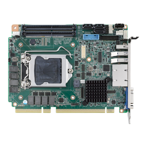
Page 16: Board Layout: Jumper And Connector Locations
Board Layout: Jumper and Connector Locations SATA0-3 DIMMA1 USB2H2 DIMMB1 USB3H1 USB2A1 USB2H1 CPUFAN1 PWR1 COM12 JWDT1-JOBS1 LANLED USB2C1 USB3C1 LPC2 USB3C2 LAN1 GPIO1 HDAUDIO1 JCASE1 Figure 1.1 Jumper and Connector Locations PCE-3032/4132 User Manual... -
Page 17: Block Diagram
Block Diagram Figure 1.2 PCE-3032 Block Diagram Figure 1.3 PCE-4132 Block Diagram PCE-3032/4132 User Manual... -
Page 18: Safety Precautions
1, 2 and 3. In this case you connect either pins 1 and 2, or 2 and 3. A pair of needle-nose pliers may be useful when set- ting jumpers. PCE-3032/4132 User Manual... -
Page 19: Bios (Jcmos1)
1.8.2 BIOS (JCMOS1) PCE-3032/4132 CPU card contains a jumper that can erase BIOS CMOS data and reset the system BIOS information. Normally this jumper should be set with pins 1-2 closed. If you want to reset those data, set JCMOS1 to 2-3 closed for just a few sec- onds, and then move the jumper back to 1-2 closed. -
Page 20: Watchdog Timer Output (Jwdt1) And Hardware Monitor Alarm (Jobs1)
Watchdog Timer Output (JWDT1) and Hardware Monitor Alarm (JOBS1) PCE-3032/4132 contains a watchdog timer that will reset the CPU in the event the CPU stops processing. This feature means PCE-3032/4132 will recover from a soft- ware failure or an EMI problem. The JWDT1 jumper settings control the outcome of what the computer will do in the event the watchdog timer is tripped. -
Page 21: Chapter 2 Connecting Peripherals
Chapter Connecting Peripherals... -
Page 22: Introduction
USB Ports (USB2A1, USB2C1, USB3C1, USB3C2, USB2H1, USB2H2, USB3H1) PCE-3032/4132 provides up to 10 x USB (Universal Serial Bus) on-board ports with complete Plug & Play and hot swap support. These USB ports comply with USB Specification 2.0 and 3.0, support transfer rates up to 480 Mbps (USB2.0), and 5 Gbps (USB3.0). -
Page 23: Vga Connector (Vga)
This CPU card has VGA outputs that can drive conventional CRT displays. VGA is a standard 15-pin D-SUB connector commonly used for VGA. DP Connector (DP2) DP2 is a 20-pin connector, supporting resolution up to 1920 x 1200. Please place order no. 1700021831-01 for standard DP connector on bracket. PCE-3032/4132 User Manual... -
Page 24: Serial Ports (Com12)
RS-232 Serial Ports (COM12) COM12 PCE-3032/4132 offers two serial ports. These ports can connect to serial devices, such as a mouse or a printer, or to a communications network. The IRQ and address ranges for both ports are fixed. However, if you want to disable the port or change these parameters later, you can do this in the system BIOS setup. -
Page 25: Front Panel Connectors (Fp1)
HDD LED, power LED, SNMP SM_Bus, reset, power on/off. Power LED status Power status Deep S5 ON Deep S5 OFF Deep S5 ON Deep S5 OFF Flash(fast) Flash(fast) Flash(fast) Flash(fast) Flash(fast) Flash(fast) Flash(fast) Flash(fast) Flash(slow) Flash(slow) Flash(slow) PCE-3032/4132 User Manual... -
Page 26: H/W Monitor/Watchdog Timer
4-5 Closed: Enables hardware monitor alarm (Default) 4-5 Open: Disables hardware monitor alarm 2.8.2 Watchdog Timer (JWDT1) This is for an setting action trigger on the watchdog timer. 2-3 Close: Enable watchdog timer (Default) 2-3 Open: No action PCE-3032/4132 User Manual... -
Page 27: Lan Ports (Lan1 & Lan2)
LAN Ports (LAN1 & LAN2) LAN1 PCE-3032/4132 is equipped with two high-performance 1000 Mbps Ethernet LANs. They are supported by all major network operating systems. The RJ-45 jacks on the rear plate provide convenient connectivity. Table 2.1: LAN LED Indicators... -
Page 28: High Definition Audio Module Interface (Hdaud1)
2.10 High Definition Audio Module Interface (HDAUD1) HDAUDIO1 This HDAUD1 pin header is the connection interface to Advantech's audio module. Note! Advantech audio module ordering information. P/N: PCA-AUDIO-HDB1E. 2.11 GPIO Header (GPIO1) GPIO1 Provides 10-Pin pin header for 8-bit Digital I/O usage. Refer to Appendix B for detailed information on the pin assignments and programming guide in Appendix C. -
Page 29: Case Open Connector (Jcase1)
2.12 Case Open Connector (JCASE1) JCASE1 The 2-pin case open connector is for chassis with a case open sensor. When the case is open, the buzzer on motherboard will beep. PCE-3032/4132 User Manual... -
Page 30: Front Panel Lan Indicator Connector (Lanled1)
LAN1 (1, 3 pin) LAN2 (2, 4 pin) 1000Mbps Link On 1000Mbps Active Flash Flash 1000Mbps Link Off 100Mbps Link On 100Mbps Active Flash Flash 100Mbps Link Off 10Mbps Link On 10Mbps Active Flash Flash 10Mbps Link Off PCE-3032/4132 User Manual... -
Page 31: Serial Ata Interface (Sata0~Sata3)
CD/DVD drivers with long cables. 2.15 LPC Extension Interface (LPC2) LPC2 LPC2 is a 14-pin female pin header for adopting Advantech LPC module, such as PCA-COM232-00A1E, PCA-COM485-00A1E, PCA-TPM-00B1E. Note! When setting PCA-COM485 to RS-422 mode, BIOS auto-flow control... -
Page 32: 12/5V Power Connector (Pwr1)
Due to no 5V supply from the golden fingers, please use a power converter: 1703040100 to connect from the peripheral power connector on the power supply to PWR1 on board. Note! Please note that if PWR1 is not connected, PCE-3032/4132 can not be powered on. PCE-3032/4132 User Manual... -
Page 33: Chapter 3 Ami Bios Setup
Chapter AMI BIOS Setup... -
Page 34: Introduction
The Setup program uses a number of menus for making changes and turning the special features on or off. This chapter describes the basic navigation of the PCE-3032/4132 setup screens. Figure 3.1 Setup Program Initial Screen... -
Page 35: Entering Setup
Press the <Tab> key or the <Arrow> keys to move between fields. The date must be entered in MM/DD/YY format. The time must be entered in HH:MM:SS format. Power Type Choose this item correspond with your power supply type. PCE-3032/4132 User Manual... -
Page 36: Advanced Bios Features Setup
Advanced BIOS Setup option by highlighting it using the <Arrow> keys. All Advanced BIOS Setup options are described in this section. The Advanced BIOS Setup screen is shown below, and the sub menus are described on the following pages. Figure 3.3 Advanced BIOS Features Setup PCE-3032/4132 User Manual... - Page 37 0 - ~ Hot Plug 1 - SHPC Native Hot Plug control 2 - ~ Power Management Events 3 - PCIe Advanced Error Reporting control 4 - PCIe Capability Structure control 5 - Latency Tolerance Reporting control PCE-3032/4132 User Manual...
- Page 38 Enable or Disable Hyper-Threading Technology. Enable/Disable AES (Advanced Encryption Standard). Intel Trusted Execution Technology Enables utilization of additional hardware capabilities provided by Intel Trusted Execution Technology. Changes require a full power cycle to take effect. PCE-3032/4132 User Manual...
- Page 39 3.2.2.3 Power & Performance PCE-3032/4132 User Manual...
- Page 40 Figure 3.6 Power & Performance CPU - Power Management CPU-Power Management Control Options. 3.2.2.4 PCH-FW Configuration Figure 3.7 PCH-FW Configuration PCE-3032/4132 User Manual...
- Page 41 3.2.2.5 Trusted Computing Figure 3.8 Trusted Computing 3.2.2.6 ACPI Settings PCE-3032/4132 User Manual...
- Page 42 Figure 3.9 ACPI Settings Enable ACPI Auto Configuration Enables or Disabled BIOS ACPI Auto Configuration. Enable Hibernation Enables or Disables System ability to Hibernate (OS/S4 Sleep State). This option may not be effective with some operating systems. PCE-3032/4132 User Manual...
- Page 43 S3 Video Repost Enable or Disable S3 Video Repost. 3.2.2.7 SMART Settings Figure 3.10 SMART Settings SMART Self Test Run SMART Self Test on all HDDs during POST. PCE-3032/4132 User Manual...
- Page 44 3.2.2.8 Super IO Configuration Figure 3.11 Super IO Configuration Serial Port 1 Configuration Set Parameters of Serial Port 1 (COMA). Serial Port 2 Configuration Set Parameters of Serial Port 2 (COMB). PCE-3032/4132 User Manual...
- Page 45 3.2.2.9 HW Monitor PCE-3032/4132 User Manual...
- Page 46 Figure 3.12 HW Monitor CPU Warning Temperature Set CPU Warning Temperature. ACPI Shutdown Temperature Set ACPI Shutdown Temperature. CPUFAN1 Smartfan Setting Fan configuration mode setting. PCE-3032/4132 User Manual...
- Page 47 Figure 3.13 S5 RTC Wake Settings Wake system from S5 Enable or disable System wake on alarm event. Select FixedTime, system will wake on the hr::min::sec specified. Select DynamicTime, System will wake on the current time + Increase minute(s). PCE-3032/4132 User Manual...
- Page 48 3.2.2.11 Serial Port Console Redirection Figure 3.14 Serial Port Console Redirection Console Redirection EMS Console Redirection Enable or Disable. PCE-3032/4132 User Manual...
- Page 49 3.2.2.12 Intel TXT Information Figure 3.15 Intel TXT Information 3.2.2.13 USB Configuration PCE-3032/4132 User Manual...
- Page 50 PCE-3032/4132 User Manual...
- Page 51 Figure 3.16 USB Configuration XHCI Hand-off This is a workaround for OSes without XHCI hand-off support. The XHCI owner- ship change should be claimed by XHCI driver. PCE-3032/4132 User Manual...
- Page 52 Controller. "Auto" uses default value: for a Root port it is 100 ms, for a Hub port the delay is taken from Hub descriptor. 3.2.2.14 Network Stack Configuration Figure 3.17 Network Stack Configuration Network stack Enable/Disable UEFI Network Stack. PCE-3032/4132 User Manual...
- Page 53 3.2.2.15 CSM Configuration Figure 3.18 CSM Configuration Enable/Disable CSM Support. PCE-3032/4132 User Manual...
-
Page 54: Chipset
3.2.2.16 NVME Configuration Figure 3.19 NVME Configuration 3.2.3 Chipset Figure 3.20 Chipset PCE-3032/4132 User Manual... - Page 55 3.2.3.1 System Agent (SA) Configuration Figure 3.21 System Agent (SA) Configuration VT-d Check to enable VT-d function on MCH. PCE-3032/4132 User Manual...
- Page 56 3.2.3.2 Graphics Configuration Primary Display Select which of IGFX/PEG/PCI Graphics device should be Primary Display or select SG for Switchable Gfx. Internal Graphics Keep IGFX enabled based on the setup options. PCE-3032/4132 User Manual...
- Page 57 Max Link Speed Configure PEG 0:1:1 Max Speed. Enable Root Port Enable or Disable the Root Port. Max Link Speed Configure PEG 0:1:2 Max Speed. PEG Port Feature Configuration PEG Port Feature Configuration. PCE-3032/4132 User Manual...
- Page 58 3.2.3.4 Memory Configuration Figure 3.23 Memory Information Maximum Memory Frequency Maximum memory frequency selections in MHz. Valid values should match the refclk, i.e. divide by 133 or 100. PCE-3032/4132 User Manual...
- Page 59 Enable or disable PowerOn by Modem. State After G3 Specify what state to go to when power is re-applied after a power failure (G3 state). PCIE Device Initial Delay The PCIE device initial delay 0~30 second. PCE-3032/4132 User Manual...
- Page 60 3.2.3.6 PCI Express Configuration Figure 3.25 PCI Express Configuration PCI Express Root Port 1~24 status PCE-3032/4132 User Manual...
- Page 61 3.2.3.7 USB Configuration Figure 3.26 USB Configuration XHCI Compliance Mode Option to enable Compliance Mode. Default is to disable Compliance Mode. Change to enable for Compliance Mode testing. PCE-3032/4132 User Manual...
- Page 62 3.2.3.8 HD Audio Configuration Figure 3.27 PCH Azalia Configuration HD Audio Control detection of the HD Audio device. Disable=HDA will be unconditionally disabled. Enable=HDA will be unconditionally enabled. Auto=HDA will be enabled if present, disabled otherwise. PCE-3032/4132 User Manual...
-
Page 63: Security
RTC Memory Lock Enable will lock bytes 38h-3Fh in the lower/upper 128-byte bank of RTC RAM. BIOS Lock Enable/Disable the PCH BIOS lock enable feature. Required to be enabled to ensure SMM protection of flash. PCE-3032/4132 User Manual... -
Page 64: Boot
Number of seconds to wait for setup activation key. Bootup NumLock State Select the keyboard Numlock state. Quiet Boot Enable/Disable Quiet Boot option. Boot Option #1 Set the system boot order. Boot Option #2 Set the system boot order. PCE-3032/4132 User Manual... -
Page 65: Save & Exit
Select this option to save user's configuration. Restore User Defaults Select this option to restore BIOS to user's configuration. *When you make some critical changes, the system will still reboot even if you chose "Save changes and exit". PCE-3032/4132 User Manual... - Page 66 PCE-3032/4132 User Manual...
-
Page 67: Chapter 4 Value-Added Software Services
Chapter Value-Added Software Services... -
Page 68: Value-Added Software Services
Advantech platforms. APIs plays the role of catalyst between developer and solution, and make Advantech embedded platforms easier and simpler to adopt and operate with customer applications. -
Page 69: Chapter 5 Chipset Software Installation Utility
Chapter Chipset Software Installation Utility... -
Page 70: Before You Begin
To facilitate the installation of the enhanced display drivers and utility software, read the instructions in this chapter carefully. The drivers for the PCE-3032/4132 are located on the software installation CD. The driver in the folder of the driver CD will guide and link you to the utilities and drivers for Windows. -
Page 71: Windows 10 Driver Setup
Insert the driver CD into your system’s CD-ROM drive. You can see the driver folder items. Navigate to the "01_Chipset" folder, choosing the operating sys- tem, and click "infinst_autol.exe" to complete the installation of the driver. Note! Wrong driver installation may cause unexpected system instability. PCE-3032/4132 User Manual... - Page 72 PCE-3032/4132 User Manual...
-
Page 73: Chapter 6 Integrated Graphic Device Setup
Chapter Integrated Graphic Device Setup... -
Page 74: Introduction
Insert the driver CD into your system’s CD-ROM drive. You can see the driver folder items. Navigate to the "02_Graphic" folder, choosing the operating system and click "setup.exe" to complete the installation of the driver. Note! Wrong driver installation may cause unexpected system instability. PCE-3032/4132 User Manual... - Page 75 Chapter LAN Configuration...
- Page 76 Introduction PCE-3032/4132 has dual Gigabit Ethernet LANs via dedicated PCI Express x1 lanes (For PCE-3032, LAN1 and LAN2 are Intel I211AT; for PCE-4132, LAN1 and LAN2 are Intel I210AT) that offer bandwidth of up to 500 MB/sec, eliminating network data flow bottlenecks and incorporating Gigabit Ethernet at 1000 Mbps.
- Page 77 Chapter Intel ME...
- Page 78 Note! ® ® If the Intel Management Engine (Intel ME) driver has not been suc- cessfully installed, you may see an error on a "PCI Simple Communica- tions Controller" in Device Manager. PCE-3032/4132 User Manual...
- Page 79 Chapter SATA RAID Setup...
- Page 80 For the detailed installation instructions for the SATA RAID driver and utility, please check the User Guide in the driver CD. Note! Before you install the Intel Rapid Storage Technology, please read the "readme.txt". PCE-3032 don't support SATA RAID mode. PCE-3032/4132 User Manual...
- Page 81 Appendix Programming the Watchdog Timer...
- Page 82 Introduction The PCE-3032/4132’s watchdog timer can be used to monitor system software oper- ation and take corrective action if the software fails to function within the programmed period. This section describes the operation of the watchdog timer and how to pro- gram it.
- Page 83 Write 1 to bit 4: Watchdog timer count mode is 1000 times faster. If bit 3 is 0, the count mode is 1/1000 seconds mode. If bit 3 is 1, the count mode is 1/1000 minutes mode. PCE-3032/4132 User Manual...
- Page 84 ; Enable the function of watchdog timer al,30h dx,al al,dx al,01h dx,al ;----------------------------------------------------------- Dec dx ; Set second as counting unit al,0f5h dx,al al,dx And al,not 08h dx,al ;----------------------------------------------------------- Dec dx ; Set timeout interval as 10 seconds and start counting al,0f6h PCE-3032/4132 User Manual...
- Page 85 ;----------------------------------------------------------- Dec dx ; Set minute as counting unit al,0f5h dx,al al,dx al,08h dx,al ;----------------------------------------------------------- Dec dx ; Set timeout interval as 5 minutes and start counting al,0f6h dx,al al,5 ; 5 minutes dx,al ;----------------------------------------------------------- PCE-3032/4132 User Manual...
- Page 86 ;----------------------------------------------------------- Dec dx ; Lock NCT6776D al,0aah dx,al Enable watchdog timer to be reset by keyboard. ;----------------------------------------------------------- Mov dx,2eh ; Unlock NCT6776D Mov al,87h Out dx,al Out dx,al ;----------------------------------------------------------- Mov al,07h ; Select registers of watchdog timer PCE-3032/4132 User Manual...
- Page 87 Out dx,al Out dx,al ;----------------------------------------------------------- Mov al,07h ; Select registers of watchdog timer dx,al al,08h dx,al ;----------------------------------------------------------- Dec dx ; Enable the function of watchdog timer al,30h dx,al al,01h dx,al ;----------------------------------------------------------- Dec dx ; Generate a time-out signal PCE-3032/4132 User Manual...
- Page 88 ;Write 1 to bit 5 of F7 register al,dx Or al,20h dx,al ;----------------------------------------------------------- Dec dx ; Lock NCT6776D al,0aah dx,al PCE-3032/4132 User Manual...
- Page 89 Appendix I/O Pin Assignments...
- Page 90 VGA Connector (VGA1) Table B.1: VGA Connector (VGA1) Signal Signal GREEN BLUE H-SYNC V-SYNC PCE-3032/4132 User Manual...
- Page 91 RS 232 Serial Port (COM12) Table B.2: RS-232 Serial Port (COM12) Signal COM1_DCD COM1_DSR COM1_SIN COM1_RTS COM1_SOUT COM1_CTS COM1_DTR COM1_RI COM2_DCD COM2_DSR COM2_SIN COM2_RTS COM2_SOUT COM2_CTS COM2_DTR COM2_RI PCE-3032/4132 User Manual...
- Page 92 Table B.3: USB 3.0 Header (USB23~USB89) Signal Signal USB_P+_P2 USB3.0_RXN_P1 USB_P-_P2 USB3.0_RXP_P1 USB3.0_TXP_P2 USB3.0_TXN_P1 USB3.0_TXN_P2 USB3.0_TXP_P1 USB3.0_RXP_P2 USB_P-_P1 USB3.0_RXN_P2 USB_P+_P1 Reserve PS/2 Keyboard/Mouse Connector (KBMS1) Table B.4: PS/2 Keyboard/Mouse Connector (KBMS1) Signal KB DATA MS DATA KB CLOCK MS CLOCK PCE-3032/4132 User Manual...
- Page 93 CPU Fan Power Connector (CPUFAN1) Table B.5: CPU Fan Power Connector (CPUFAN1) Signal +12V Detect Front Panel Connector (FP1) Table B.6: Front Panel Connector (FP1) Signal HDD_LED+ HDD_LED- PW_LED SNMP_SCL SNMP_SDA RESET# PWR-BTN PCE-3032/4132 User Manual...
- Page 94 High-definition Audio Link Connector (HDAUD1) Table B.7: High-definition Audio Link Connector (HDAUD1) Signal Signal ACZ_VCC ACZ_SYNC ACZ_BITCLK ACZ_SDOUT ACZ_SDIN0 ACZ_SDIN1 -ACZ_RST ACZ_12V LAN1 and LAN2 LED Connector (LANLED1) Table B.8: LAN1 and LAN2 LED Connector (LANLED1) Signal #LAN1_ACT #LAN2_ACT V33_AUX V33_AUX PCE-3032/4132 User Manual...
- Page 95 GPIO Header (GPIO1) Table B.9: GPIO Header (GPIO1) Signal SIO_GPIO0 SIO_GPIO4 SIO_GPIO1 SIO_GPIO5 SIO_GPIO2 SIO_GPIO6 SIO_GPIO3 SIO_GPIO7 VCC_GPIO B.10 JWDT1 and JOBS1 Table B.10: JWDT1 and JOBS1 Signal SIO_WG# SRST# ERR_BEEP OBS_BEEP PCE-3032/4132 User Manual...
- Page 96 B.11 JCASE1 Table B.11: JCASE1 Signal CASEOP# B.12 LPC2 Table B.12: LPC2 Signal CLK33M_LPC0 LPC_AD1 PLTRST_LPC0# LPC_AD0 LPC_FRAME# 3.3V LPC_AD3 LPC_AD2 LPC1_SMB_CLK PCI_SERIRQ LPC1_SMB_DATA 5VSB 5VSB PCE-3032/4132 User Manual...
- Page 97 Table B.13: PWR1 Signal B.14 DP1, DVI1 Table B.14: DP1, DVI1 Signal DDPB TX0- B DDPB TX3- B DDPB TX0+ B DDPB TX3+ B DDPB TX1- B DDPB TX1+ B TMDS0_DDB_DAT(PCE-4128) DDPB_AUX- (PCE-3028) TMDS0_DDB_CLK (PCE-4128) DDPB_AUX+ (PCE-3028) PCE-3032/4132 User Manual...
- Page 98 LPC/eSPI or PCIe 84h - 86h Reserved LPC/eSPI or PCIe LPC/eSPI or PCIe Reserved LPC/eSPI or PCIe LPC/eSPI or PCIe 8Ch - 8Eh Reserved LPC/eSPI or PCIe LPC/eSPI or PCIe (Alias to 80h) (Alias to 80h) Forwarded to LPC/eSPI PCE-3032/4132 User Manual...
- Page 99 Table B.16: System I/O Ports I/O Address (Hex) Device A10h-A1Fh H/W Monitor 2F8h-2FFh Communication Port (COM2) 378h-37Fh ECP Printer Port (LPT1) 3B0h-3BBh Graphics 3C0h-3DFh Graphics 3F8h-3FFh Communication Port (COM1) 1800h-18FFh PMBASE 778h-77Fh ECP Printer Port 240h-25Fh Communication Port for PCA-COM232/485 module PCE-3032/4132 User Manual...
- Page 100 B.18 1 MB Memory Map Table B.18: 1 MB Memory Map Address Range Device E8000h - FFFFFh BIOS D0000h - E7FFFh Unused C0000h - CFFFFh VGA BIOS A0000h - BFFFFh Video Memory 00000h - 9FFFFh Base memory PCE-3032/4132 User Manual...
- Page 101 Appendix Programming the GPIO...
- Page 102 Configure logical device, configuration register CRE0,CRE1,CRE2 --------------------------------------------------------------- MOV DX,2EH MOV AL,09H OUT DX,AC DEC DX MOV AL,30H OUT DX,AL INC DX IN AL,DX OR AL,10000000B DEC DX MOV AL,07H OUT DX,AL INC DX MOV AL,07H ; Select logical device 7 PCE-3032/4132 User Manual...
- Page 103 ;Set GPIO is normal not inverter OUT DX,AL; DEC DX MOV AL,E1H OUT DX,AL INC DX MOV AL,??H ; Put the output value into AL OUT DX,AL ------------------------------------------ Exit extended function mode | ------------------------------------------ MOV DX,2EH MOV AL,AAH OUT DX,AL PCE-3032/4132 User Manual...
- Page 104 No part of this publication may be reproduced in any form or by any means, electronic, photocopying, recording or otherwise, without prior written permis- sion of the publisher. All brand and product names are trademarks or registered trademarks of their respective companies. © Advantech Co., Ltd. 2021...
Need help?
Do you have a question about the PCE-3032 and is the answer not in the manual?
Questions and answers