Table of Contents
Advertisement
Quick Links
Advertisement
Table of Contents

Related Manuals for Advantech PCM-9581


Summary of Contents for Advantech PCM-9581
- Page 1 PCM-9581 Intel Pentium M SBC with Audio, VGA, LCD Users’ Manual...
- Page 2 Creative is a trademark of Creative Technology LTD. CHRONTEL is a trademark of Chrontel Inc. All other product names or trademarks are properties of their respective owners. For more information on this and other Advantech products, please visit our websites at: http://www.advantech.com http://www.advantech.com/epc For technical support and service, please visit our support website at: http://support.advantech.com...
-
Page 3: Packing List
Packing List Before you begin installing your card, please make sure that the following materials have been shipped: • 1 PCM-9581 all-in-one single board computer • 1 CD disk for utility and drivers • 1 startup manual • 1 Mini Jumper*10 PCS Package (p/n: 9689000002) •... - Page 4 There is a danger of a new battery exploding if it is incorrectly installed. Do not attempt to recharge, force open, or heat the battery. Replace the battery only with the same or equivalent type recommended by the manufacturer. Discard used batter- ies according to the manufacturer’s instructions. PCM-9581 User’s Manual...
- Page 5 Additional Information and Assistance 1. Visit the Advantech web site at www.advantech.com where you can find the latest information about the product. 2. Contact your distributor, sales representative, or Advantech's customer service center for technical support if you need additional assistance.
- Page 6 PCM-9581 User’s Manual...
-
Page 7: Table Of Contents
Contents Chapter 1 Introduction ............2 Introduction ............... 2 Features ................2 Specifications ..............3 Board layout: dimensions..........6 Figure 1.1:Board layout: dimensions (component side). 6 Figure 1.2:Board layout: dimensions (solder side)..7 Chapter 2 Installation ............10 Jumpers................10 Table 2.1:Jumpers............10 2.1.1 Jumpers setting drawing .......... - Page 8 Figure 4.9:Frequency/Voltage Control ......37 4.2.10 Load Optimized Defaults..........38 4.2.11 Set Password ..............38 4.2.12 Save & Exit Setup............39 4.2.13 Exit Without Saving............39 Chapter 5 PCI Graphic Setup.........42 Introduction ..............42 5.1.1 Chipset ................42 PCM-9581 User’s Manual viii...
- Page 9 5.1.2 Display memory............42 5.1.3 Display types..............42 5.1.4 Dual/Simultaneous Display .......... 43 Figure 5.1:Selecting Display Settings......44 Installation of the PCI Graphic driver ......45 5.2.1 Installation for Windows 98/ME/2000/XP ....45 Further Information ............47 Chapter 6 Audio Setup.............50 Introduction ..............
- Page 10 Appendix D Optional Extras ..........100 PCM-10586-6100 Cable kit for PCM-9581F....100 Table D.1:PCM-10586-6100 wiring kit 9581F ..100 PCM-10586-6A00 Cable kit for PCM-9581FG... 101 Optional USB cable (CN25,26,27) ......102 ATX Power Control Cable (CN15)....... 102 Appendix E Mechanical Drawings........104 PCM-9581 User’s Manual...
-
Page 11: General Information
General Information This chapter gives background information on the PCM-9581. Sections include: • Introduction • Features • Specifications • Board layout and dimensions Chapter 1... -
Page 12: Chapter 1 Introduction
Chapter 1 Introduction 1.1 Introduction The PCM-9581 is a solid, general purpose single board computer (SBC) to satisfy various industrial and multimedia applications. With socket 478 or onboard Pentium M 1.1 G, 1.6G(optional), Gigabit Ethernet, USB 2.0, ECC DDR memory, 2 channel 36-bit or 48-bit (optional) LVDS, TV-out function and Mini-PCI interface, the PCM-9581’s design is based on the... -
Page 13: Specifications
1.3 Specifications Standard SBC Functions • CPU: Supports onboard Intel® Pentium® M and Celeron® M or socket478 • BIOS: Award 256 KB Flash memory • System memory: Two 184 pin DIMM sockets, support ECC Double Data Rate (DDR)128 MB to 2 GB, accepts 128/256/512/1000 MB DDR200/266 DRAM. - Page 14 • Intel 82551ER [Intel 82551QM optional] (PCM-9581F) • Intel 82540EM (PCM-9581FG) • Ethernet interface: • IEEE 802.3u 100BASE-T Fast Ethernet compatible (PCM-9581F) • IEEE 802.3z/ab 1000 BASE-T Gigabit Ethernet compatible (PCM- 9581FG) • I/O address switchless setting • Built-in boot ROM PCM-9581 User’s Manual...
- Page 15 Audio Function (optional) • Chipset: Intel 82801DB (ICH4) • Audio controller: AC’97 3D surround stereo sound • Supports Speaker out, CD-input, Line-in, Line-out, Microphone Mechanical and Environmental • Dimensions: (L x W)203 x 146 mm (8" x 5.75") • Power supply Voltage:ATX, with Vcore 2 phase, +5V power only can work •...
-
Page 16: Board Layout: Dimensions
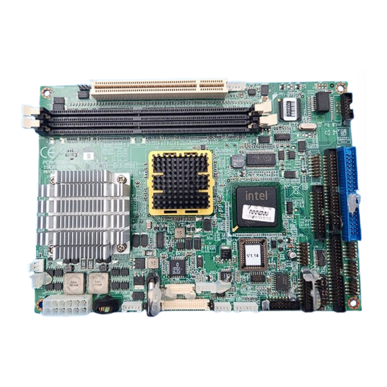
A D V A N T E C H P C M -95 81 R E V . A 1 19 A 69 58 10 0 M A D E IN T A IW A N Figure 1.1: Board layout: dimensions (component side) PCM-9581 User’s Manual... -
Page 17: Figure 1.2:Board Layout: Dimensions (Solder Side)
Figure 1.2: Board layout: dimensions (solder side) Chapter 1... - Page 18 PCM-9581 User’s Manual...
- Page 19 Installation This chapter explains the setup proce- dures of PCM-9581 hardware, includ- ing instructions on setting jumpers and connecting peripherals, switches and indicators. Be sure to read all safety precautions before you begin the instal- lation procedure. Chapter 2...
-
Page 20: Chapter 2 Installation
Chapter 2 Installation 2.1 Jumpers The PCM-9581 has a number of jumpers that allow you to configure your system to suit your application. The table below lists the functions of the various jumpers. Table 2.1: Jumpers Label Function PCI VIO Select RS 232/422/485 Select CMOS Charge &... - Page 21 JP2: RS 232/422/485 Select PINS RS-232 RS-422 RS-485 Open Open Close Open Close Open Close Open Open Close Open Open 8,10 Close Open Open 9,11 Open Close Close 10,12 Open Close Close 13,15 Close Open Open 14,16 Close Open Open 15,17 Open Close...
-
Page 22: Connectors
□ ○ ■ ■ 2.2 Connectors On-board connectors link the PCM-9581 to external devices such as hard disk drives, a keyboard, or floppy drives. The table below lists the func- tion of each of the board’s connectors. Table 2.2: Connectors... - Page 23 Table 2.2: Connectors CN15 ATX Power Connector CN16 DF13 40Pin LVDS Connector CN17 Inverter Connector CN18 CD-IN Connector CN19 PS2 KB/MS Connector CN20 Compact Flash Connector CN22 Mini PCI Connector CN23 10/100 M LAN Connector CN24 SIR Connector CN25 USB 0,1 Connector CN26 USB 2,3 Connector CN27...
-
Page 24: Locating Jumpers And Connectors
A D VA N T E C H P C M -9 5 81 R E V . A 1 19 A 69 58 1 0 0 M A D E IN T A IW A N Figure 2.1: Jumper & Connector (component side) PCM-9581 User’s Manual... -
Page 25: Figure 2.2:Jumper & Connector (Solder Side)
Figure 2.2: Jumper & Connector (solder side) Chapter 2... -
Page 26: Setting Jumpers
A pair of needle-nose pliers may be helpful when working with jumpers. If you have any doubts about the best hardware configuration for your application, contact your local distributor or sales representative before you make any changes. Generally, you simply need a standard cable to make most connections. PCM-9581 User’s Manual... -
Page 27: Clear Cmos (Jp3)
2.5 Clear CMOS (JP3) Warning! To avoid damaging the computer, always turn off the power supply before setting “Clear CMOS.” Before turning on the power supply, set the jumper back to “3.0 V Battery On.” This jumper is used to erase CMOS data and reset system BIOS informa- tion. -
Page 28: Ide, Cdrom Hard Drive Connector (Cn5, Cn6)
2.7 IDE, CDROM hard drive connector (CN5, CN6) The PCM-9581 provides 2 IDE channels which you can attach up to four Enhanced Integrated Device Electronics hard disk drives or CDROM to the PCM-9581’s internal controller. The PCM-9581's IDE controller uses a PCI interface. -
Page 29: Floppy Drive Connector (Cn8)
2.9 Floppy drive connector (CN8) You can attach up to two floppy drives to the PCM-9581’s on-board con- troller. This is useful for notebooks with 26 pin slim-FDD cable (part no:1906000001), for example. You can use any combination of 5.25”(360 KB and 1.2MB) and/or 3.5”(720 KB, 1.44MB, and 2.88 MB) drives. -
Page 30: Parallel Port Connector (Cn4)
You can select ECP/EPP/SPP DMA channel via BIOS setup. 2.11 Keyboard and PS/2 mouse connector (CN19) The PCM-9581 board provides a keyboard connector that supports both a keyboard and a PS/2 style mouse. In most cases, especially in embedded applications, a keyboard is not used. If the keyboard is not present, the standard PC/AT BIOS will report an error or fail during power-on self- test (POST) after a reset. -
Page 31: Power Connectors (Cn10,Cn15)
2.13 Power connectors (CN10,CN15) 2.13.1 ATX power connector, +5V (CN15) Supplies main power to the PCM-9581 (+5V) and to devices that require. 2.13.2 CPU Fan power supply connector (CN10) Provides power supply +12V to CPU cooling fan, and fan speed detects signal input. -
Page 32: Cd Audio-In Connector (Cn18)
2.15.2 CD audio-in connector (CN18) All CD-ROM drives can provide analog audio signal output when used as a music CD player. The CN18 on PCM-9581 is a connector to input CD audio signal into the audio controller. The audio cable of your CD-ROM drive will be used to connect to CN18. -
Page 33: Dvi Lcd Panel Connector(Cn7)
Digital Visual Interface (DVI) is the standard interface for high-perfor- mance connection between PCs and Flat Panel Displays, Digital CRT dis- plays, Projectors, and HDTV. The PCM-9581 is able to drive a DVI connector display at a pixel resolution up to 1600 x 1200 at 85Hz. -
Page 34: 1000Base-T Connector (Cn2, Pcm-9581Fg)
CD disc. 2.20 USB connectors (CN25,CN26,CN27) The PCM-9581 board provides up to six USB (Universal Serial Bus) 1.1/ 2.0 ports. This gives complete Plug and Play, and hot attach/detach for up to 127 external devices. The USB interfaces comply with USB specifica- tion Rev. - Page 35 Software Configuration This chapter details the software con- figuration information. It shows you how to configure the card to match your application requirements. The AWARD System BIOS is covered in Chapter 4. Sections include: • Introduction • Connections for standard LCDs •...
-
Page 36: Chapter 3 Software Configuration
Chapter 3 Software Configuration 3.1 Introduction The PCM-9581 system BIOS and custom drivers are located in a 256 Kbyte, Flash ROM device, designated U6. A single Flash chip holds the system BIOS, VGA BIOS and network Boot ROM image. The display can be configured via CMOS settings. -
Page 37: Connections To Three Standard Lcds
3.2 Connections to Three Standard LCDs The following tables illustrate typical LCD connection pinouts for the PCM-9581. 3.2.1 LG LM150X06 (1024x768(16 colors) LVDS LCD) Table 3.1: Connections to LCD/ Flat Panel (CN16) LCD Connector Flat Panel Connector Unipac-UB104S01 DF-13 40P... - Page 38 PCM-9581 User’s Manual...
- Page 39 Chapter 4 Ducks that Need Love! Award BIOS Setup This chapter describes how to set BIOS configuration data.
-
Page 40: Chapter 4 Award Bios Setup
The CMOS memory has lost power and the configuration informa- tion has been erased. The PCM-9581 Series' CMOS memory has an integral lithium battery backup. The battery backup should last ten years in normal service, but when it finally runs down, you will need to replace the complete unit. -
Page 41: Award Bios Setup
4.2 Award BIOS setup Award’s BIOS ROM has a built-in Setup program that allows users to modify the basic system configuration. This type of information is stored in battery-backed CMOS RAM so that it retains the Setup information when the power is turned off. 4.2.1 Entering setup Power on the computer and press <Del>... -
Page 42: Standard Cmos Features Setup
4.2.2 Standard CMOS Features setup When you choose the Standard CMOS Features option from the Initial Setup Screen menu, the screen shown below is displayed. This standard Setup Menu allows users to configure system components such as date, time, hard disk drive, floppy drive and display. Once a field is high- lighted, on-line help information is displayed in the left bottom of the Menu screen. -
Page 43: Advanced Bios Features Setup
4.2.3 Advanced BIOS Features setup By choosing the Advanced BIOS Features Setup option from the Initial Setup Screen menu, the screen below is displayed. This sample screen contains the manufacturer’s default values for the PCM-9581 Series. Figure 4.3: Advanced BIOS Features setup... -
Page 44: Advanced Chipset Features Setup
4.2.4 Advanced Chipset Features setup By choosing the Advanced Chipset Features option from the Initial Setup Screen menu, the screen below is displayed. This sample screen contains the manufacturer’s default values for the PCM-9581 Series. Figure 4.4: Advanced Chipset Features setup 4.2.5 Integrated Peripherals Choosing the Integrated Peripherals option from the Initial Setup Screen menu should produce the screen below. -
Page 45: Power Management Setup
4.2.6 Power Management Setup By choosing the Power Management Setup option from the Initial Setup Screen menu, the screen below is displayed. This sample screen contains the manufacturer’s default values for the PCM-9581 Series. Figure 4.6: Power Management Setup 4.2.7 PnP/PCI Configurations By choosing the PnP/PCI Configurations option from the Initial Setup Screen menu, the screen below is displayed. -
Page 46: Pc Health Status
4.2.8 PC Health Status The PC Health Status option displays information such as CPU and moth- erboard temperatures, fan speeds, and core voltage. Figure 4.8: PC Health Status PCM-9581User’s Manual... -
Page 47: Frequency/Voltage Control
4.2.9 Frequency/Voltage Control By choosing the Frequency/Voltage Control option from the Initial Setup Screen menu, the screen below is displayed. This sample screen contains the manufacturer’s default values for the PCM-9581 Figure 4.9: Frequency/Voltage Control Caution Incorrect settings in Frequency/Voltage Control may damage the system CPU, video adapter, or other hardware. -
Page 48: Load Optimized Defaults
Load Optimized Defaults loads the default system values directly from ROM. If the stored record created by the Setup program should ever become corrupted (and therefore unusable), these defaults will load auto- matically when you turn the PCM-9581 Series system on. 4.2.11 Set Password Note... -
Page 49: Save & Exit Setup
At the “Confirm Password” prompt, retype the new password, and press <Enter>. Select Save to CMOS and EXIT, type <Y>, then <Enter>. To Disable Password Choose the Set Password option from the CMOS Setup Utility main menu and press <Enter>. When you see “Enter Password,”... - Page 50 PCM-9581User’s Manual...
- Page 51 PCI Graphic Introduction Installation of PCI Graphic drivers -for Windows 98/2000/XP Further information Chapter 5...
-
Page 52: Chapter 5 Pci Graphic Setup
The PCM-9581 has an onboard PCI/AGP flat panel/VGA interface. The specifications and features are described as follows: 5.1.1 Chipset The PCM-9581 uses a Intel 855GME + Chrontel 7009 chipset for its graphic controller. It supports LVDS LCD displays, conventional analog CRT monitors, DVI connection, and TV-out function. -
Page 53: Dual/Simultaneous Display
5.1.4 Dual/Simultaneous Display The PCM-9581 uses a Intel 855GME Chrontel 7017 controller that is capable of providing simultaneous dual view display of the same content on a flat panel and CRT. To set up dual view (simultaneous mode) under Windows 9x, Windows ME, Windows NT/2000/XP, follow these steps: Step 1. -
Page 54: Figure 5.1:Selecting Display Settings
Figure 5.1: Selecting Display Settings PCM-9581 User’s Manual... -
Page 55: Installation Of The Pci Graphic Driver
5.2 Installation of the PCI Graphic driver Complete the following steps to install the PCI graphic driver. Follow the procedures in the flow chart that apply to the operating system that you are using within your PCM-9581. Notes: 1. The windows illustrations in this chapter are intended as examples only. - Page 56 Press “Yes” to reboot. PCM-9581 User’s Manual...
-
Page 57: Further Information
5.3 Further Information For further information about the AGP/VGA installation in your PCM- 9581, including driver updates, troubleshooting guides and FAQ lists, visit the following web resources: Advantech websites: www.advantech.com www.advantech.com.tw Chapter 5... - Page 58 PCM-9581 User’s Manual...
- Page 59 Audio Setup The PCM-9581F is equipped with an audio interface that records and plays back CD-quality audio. This chapter provides instructions for installing the software drivers included on the audio driver diskettes. Chapter 6...
-
Page 60: Chapter 6 Audio Setup
6.2.1 Before you begin Please read the instructions in this chapter carefully before you attempt installation. The audio drivers for the PCM-9581 board are located on the audio driver CD. Run the supplied SETUP program to install the drivers; don’t copy the files manually. - Page 61 Step 1. To install Audio driver for Windows 98/2000/XP, please run the set up wizard "Install Shield Wizard for Realtek AC'97 Audio" in CD-ROM. Example of installation steps is shown as bellow. Chapter 6...
- Page 62 Step 2. In the Hardware Update Wizard window, click "Next". Step 3. In the following Hardware Update Wizard window, click "Fin- ish" for Windows to complete audio driver installation. PCM-9581 User’s Manual...
- Page 63 Chapter 6...
- Page 64 PCM-9581 User’s Manual...
-
Page 65: Lan Configuration
LAN Configuration • Introduction • Features • Installation of Ethernet Driver for - Windows 2000 Drivers Setup Steps - Windows NT Drivers Setup Steps -Windows Wake-on-LAN Setup Chapter 7... -
Page 66: Chapter 7 Pci Bus Ethernet Interface
7.3 Installation of Ethernet Driver Before installing the Ethernet driver, note the procedures below. You must know which operating system you are using in your PCM-9581, and then refer to the corresponding installation procedure. Then just follow the steps described. You will quickly and successfully complete the installation, even if you are not familiar with instructions for Windows. -
Page 67: Installation For Windows 2000
7.3.1 Installation for Windows 2000 Note: The CD-ROM drive is designated as "D" throughout this section. Click "Setup" icon in path "D:\BISCUIT\9581\LAN\" Chapter 7... - Page 68 Choose "Modify" item and click "Next" to go next step. Highlight "Drivers for wired Ethernet adapters" and click "Next". PCM-9581 User’s Manual...
- Page 69 Click "Install" to begin the installation. Click "Finish" to exit the wizard. Chapter 7...
- Page 70 Then the Installer will show the result after driver installed. PCM-9581 User’s Manual...
-
Page 71: Installation For Windows Nt
7.3.2 Installation for Windows NT 1. Select "Start", "Settings", "Control Panel" and double click "Network" icon. 2. Then this menu will show on the screen. And click "Yes" to install net- work driver. Chapter 7... - Page 72 3. Select "Wired to the network" and click "Next" 4. Click "Start Search" to search a Network Adapter. Then click "Next" to go next step PCM-9581 User’s Manual...
- Page 73 5. Base on current network environment to modify the Network Protocol then Click "Next" Chapter 7...
- Page 74 6.Click "Next" to go to next step 7. Click "Next" to install Network Adapter driver. PCM-9581 User’s Manual...
- Page 75 8. Check the License Agreement first then select "I accept the terms in the license agreement" and click "Next". 9. Select "Typical" and Click "Next". Chapter 7...
- Page 76 10. Click "Install" to start to install driver. 11. Click "Finish" to finish install driver. PCM-9581 User’s Manual...
-
Page 77: Further Information
7.4 Further information Intel website: www.intel.com Advantech websites: www.advantech.com www.advantech.com.tw Chapter 7... - Page 78 PCM-9581 User’s Manual...
- Page 79 Programming the GPIO and Watchdog Timer The PCM-9581 is equipped with a watchdog timer that resets the CPU or generates an interrupt if processing comes to a standstill for any reason. This feature ensures system reliability in industrial standalone or unmanned environments.
-
Page 80: Appendix A Prog. Gpio & W'dog Timer
Extended Function Index Registers (EFIRs) The EFIRs are write-only registers with port address 2Eh or 4Eh on PC/ AT systems. Extended Function Data Registers (EFDRs) the EFDRs are read/write registers with port address 2Fh or 4Fh on PC/ AT systems. PCM-9581 User’s Manual... -
Page 81: Gpio Example Program-1
A.1.2 GPIO Example program-1 ------------------------------------------------ Enter the extended function mode, interruptible double-write ------------------------------------------------ MOV DX,2EH MOV AL,87H OUT DX,AL OUT DX,AL --------------------------------------------------------------- Configured logical device 7(GP10~GP17), configuration register CRF0,CRF1,CRF2 --------------------------------------------------------------- MOV DX,2EH MOV AL,07H; point to Logical Device Number Reg. OUT DX,AL MOV DX,2FH MOV AL,07H;... - Page 82 OUT DX,AL MOV DX,2FH MOV AL,??H; Put the output value into AL ??H OUT DX,AL ------------------------------------------ Exit extended function mode | ------------------------------------------ MOV DX,2EH MOV AL,AAH OUT DX,AL PCM-9581 User’s Manual...
-
Page 83: Watchdog Programming
A.2 Watchdog programming Bellow is a sample of programming code for controlling the Watchdog Timer function. ----------------------------------------------------------------------------------- Enter the extended function mode, interruptible double-write | ----------------------------------------------------------------------------------- MOV DX,2EH MOV AL,87H OUT DX,AL OUT DX,AL ----------------------------------------------------------------------------- Configured logical device 8, configuration register CRF6 | ----------------------------------------------------------------------------- MOV DX,2EH MOV AL,07H;... - Page 84 MOV DX,2EH MOV AL,F6H OUT DX,AL MOV DX,2FH MOV AL,05H; Set 5 seconds OUT DX,AL ;------------------------------------------ ; Exit extended function mode | ;------------------------------------------ MOV DX,2EH MOV AL,AAH OUT DX,AL PCM-9581 User’s Manual...
-
Page 85: Pin Assignments
Pin Assignments This appendix provides specialized information regarding: • CPU Fan Power Connector • Ethernet 10/100Base-T Connector • Ethernet 100/1000Base-T Connector • Ethernet LED connector • Audio Connector • Main Power Connector • Keyboard and PS/2 Mouse Connector • Floppy Drive Connector •... -
Page 86: Appendix B Pin Assignments
Appendix B Pin Assignments B.1 CPU fan connector (CN10) Table B.1: CPU Fan connector(CN10) Signal +12V SPEED DETECT PCM-9581 User’s Manual... -
Page 87: Ethernet 10/100Base-T Connector (Cn23)
B.2 Ethernet 10/100Base-T Connector (CN23) Table B.2: Ethernet 10/100Base-T connector (CN23) Signal VCC_LAN ACTLED LILED Chapter B... -
Page 88: Ethernet 10/100/1000 Base-T Connector (Cn2)
B.3 Ethernet 10/100/1000 BASE-T connector (CN2) Table B.3: Ethernet 100/1000-T connector (CN2) Signal RJ45 PIN7 RJ45 PIN8 RJ45 PIN4 RJ45 PIN5 RJ45 PIN3 RJ45 PIN6 RJ45 PIN1 RJ45 PIN2 PCM-9581 User’s Manual... -
Page 89: Ethernet Led Connector(Cn1)
B.4 Ethernet LED connector(CN1) Table B.4: Giga bit Ethernet LED (CN1) Signal LINK LINK100 LINK1000 B.5 ACLink audio connector (CN14) Table B.5: Audio connector Signal Signal SPK_R+ SPK_R- SPK_L+ SPK_L- LOUT_R LOUT_L LIN_R LIN_L Chapter B... -
Page 90: Cd-In Connector (Cn18)
B.6 CD-IN Connector (CN18) Table B.6: CD-IN Connector (CN18) Signal CD_L CD_R B.7 ATX Main Power Connector (CN15) Table B.7: ATX power connector (CN15) Signal Signal 5VSB PS-ON# PCM-9581 User’s Manual... -
Page 91: Keyboard And Ps/2 Mouse Connector (Cn19)
B.8 Keyboard and PS/2 Mouse Connector (CN19) Table B.8: Keyboard and mouse connector (CN19) Signal KB CLOCK KB DATA MS CLOCK MS DATA Chapter B... -
Page 92: Floppy Disk Drive Connector (Cn8)
Vcc (5 V) DRIVE SELECT 0 Vcc (5 V) DISK CHANGE NC (READY) NC (HD OUT) MOTOR ON DIRECTION SELECT NC (1.6 MB IN) STEP WRITE DATA WRITE GATE TRACK 00 WRITE PROTECT READ DATA SIDE SELECT PCM-9581 User’s Manual... -
Page 93: Ide Hard Drive Connector (Cn5, Cn6)
B.10 IDE Hard Drive Connector (CN5, CN6) Table B.10: IDE HDD connector (CN5, CN6) Signal Signal Reset DIOW DIOR IORDY DACK IDE IRQ IOCS16 ADDR 1 ADDR 0 ADDR 2 HD SELECT0 HD SELECT 1 IDE ACTIVE* Chapter B... -
Page 94: Parallel Port Connector (Cn4)
B.11 Parallel Port Connector (CN4) Table B.11: Parallel Port Connector (CN4) Signal Signal STROBE* AUTOFD* INIT* SLCTINI* ACK* BUSY SLCT * low active PCM-9581 User’s Manual... -
Page 95: Front Panel Led (Cn3)
B.12 Front Panel LED (CN3) Table B.12: 1 HDD LED+ Signal Signal HDD LED HDD LED - Power LED+ POWER LED- SUS LED+ SUS LED- LAN ACT+ LAN ACT- LAN Link + LAN Link - PWR BTN+ PWR BTN- RESET+ RESET- Chapter B... -
Page 96: Usb Connector (Cn25,26,27)
B.13 USB Connector (CN25,26,27) Table B.13: USB Connector (CN25,26,27) Signal Signal +5 V +5 V UV0-/2-/4- UV1-/3-/5- UV0+/2+/4+ UV1+/3+/5+ B.14 SIR Connector (CN24) Table B.14: USB Connector (CN24) Signal Signal IRRX IRTX PCM-9581 User’s Manual... -
Page 97: Tv Out Connector (Cn12)
B.15 TV Out Connector (CN12) Table B.15: TV Out Connector (CN12) Signal CVBS Chapter B... -
Page 98: Lcd Inverter Backlight Connector (Cn17)
B.16 LCD Inverter Backlight Connector (CN17) Table B.16: Inverter Backlight Connector (CN17) Signal +12 V ENABKL +5 V B.17 CRT Display Connector (CN13) Table B.17: CRT Display Connector (CN13) Signal Signal DDC POWER(+5V) GREEN BLUE DDC DATA H-SYNC V-SYNC DDC CLOCK PCM-9581 User’s Manual... -
Page 99: Lvds Connector (Cn16)
B.18 LVDS Connector (CN16) Table B.18: CRT Display Connector (CN13) Signal Signal LCD VDD (+3.3V) LCD VDD (+3.3V) LCD VDD (+3.3V) LCD VDD (+3.3V) OD0- ED0- OD0+ ED0+ O31- ED1- OD1+ ED1+ OD2- ED2- OD2+ ED2+ OCK- ECK- OCK+ ECK+ DDC_CLK DDC_DAT OD3-... -
Page 100: Com Port Connector (Cn11)
COM2 CTS COM2 DTR/485RX- COM2 RI COM3 DCD COM3 DSR COM3 RX COM3 RTS COM3 TX COM3 CTS COM3 DTR COM3 RI COM4 DCD COM4 DSR COM4 RX COM4 RTS COM4 TX COM4 CTS COM4 DTR COM4 RI PCM-9581 User’s Manual... -
Page 101: Compactflash Card Connector (Cn20)
B.20 CompactFlash Card Connector (CN20) Table B.20: CompactFlash Card Connector (CN20) Signal Signal SDD3 SDD4 SDD5 SDD6 SDD7 SDCS#1 SDA2 SDA1 SDA0 SDD0 SDD1 SDD2 SDD11 SDD12 SDD13 SDD14 SDD15 SDCS#3 SDIOR SDIOW IRQ15 CSEL IDERST SDIORDY SDDASP S66DET SDD8 SDD9 SDD10 Chapter B... -
Page 102: Gpio Connector (Cn9)
B.21 GPIO Connector (CN9) Table B.21: GPIO Connector (CN9) Signal GPIO0 GPIO4 GPIO1 GPIO5 GPIO2 GPIO6 GND- GPIO3 GPIO7 PCM-9581 User’s Manual... -
Page 103: Tmds Connector(Cn7)
B.22 TMDS Connector(CN7) Table B.22: TMDS Connector(CN7) Signal Signal DVI_CLK DVI_DATA HP_DET MI2C DATA MI2C CLK Chapter B... -
Page 104: Mini Pci Connector
Signal TIP Key RING Key 8PMJ-33, 4 8PMJ-13, 4 8PMJ-63, 4 8PMJ-23, 4 8PMJ-73, 4 8PMJ-43, 4 8PMJ-83, 4 8PMJ-53, 4 LED1_GRNP LED2_YELP LED1_GRNN LED2_YELN CHSGND RESERVED INTB# 3.3V INTA# RESERVED RESERVED GROUND 3.3VAUX RST# GROUND 3.3V PCM-9581 User’s Manual... - Page 105 System Assignments This Appendix contains information of a detailed nature: It includes: • System I/O ports • 1st MB memory map • DMA channel assignments • Interrupt assignments Appendix C...
-
Page 106: Appendix C System Assignments
3C0-3CF Reserved 3D0-3DF Color/graphics monitor adapter 3E8-3EF Series port 3 3F0-3F7 Diskette controller 3F8-3FF Serial port 1 * PNP audio I/O map range from 220 ~ 250H (16 bytes) MPU-401 select from 300 ~ 330H (2 bytes) PCM-9581 User’s Manual... -
Page 107: 1St Mb Memory Map
C.2 1st MB memory map Table C.2: 1st MB memory map Addr. range (Hex) Device F0000h - FFFFFh System ROM *CC000h - EFFFFh Unused (reserved for Ethernet ROM) C0000h - CBFFFh Expansion ROM (for VGA BIOS) B8000h - BFFFFh CGA/EGA/VGA text B0000h - B7FFFh Unused A0000h - AFFFFh... -
Page 108: Interrupt Assignments
IRQ 15 Secondary IDE for CFC * Ethernet interface IRQ select: 9, 11, 15 * PNP audio IRQ select: 9, 11, 15 * PNP USB IRQ select: 9, 11, 15 * PNP ACPI IRQ select: 9, 11, 15 PCM-9581 User’s Manual... - Page 109 Optional Extras for the PCM-9581 Appendix D...
-
Page 110: Appendix D Optional Extras
Appendix D Optional Extras The PCM-9581 requires several cables for normal operation. You can make them yourself or purchase an optional cable kit assembly, which includes the following: D.1 PCM-10586-6100 Cable kit for PCM-9581F Table D.1: PCM-10586-6100 wiring kit 9581F Part No. -
Page 111: Pcm-10586-6A00 Cable Kit For Pcm-9581Fg
D.2 PCM-10586-6A00 Cable kit for PCM-9581FG Table D.2: PCM-10586-6A00 wiring kit for PCM-9581FG Part No. Cable PCM-9581F Terminating Description Connector Connector 1701100151 Network,1000 RJ45 8-pin modular Base-T jack 1701260250 Parallel Port 25pin,female D- 1701440350 2.5 and 1.8 IDE 44-pin, 2mm,female cable IDC (350mm) 1701400452... -
Page 112: Optional Usb Cable (Cn25,26,27)
D.3 Optional USB cable (CN25,26,27) Optional USB cable (10-pin,26 cm) Part no: 1703100260 Optional USB cable (10pin,12cm) Part no. 1703100121 for MBPC-300 D.4 ATX Power Control Cable (CN15) part no.: 1700000265 PCM-9581 User’s Manual... -
Page 113: Mechanical Drawings
Mechanical Drawings Appendix E... -
Page 114: Appendix E Mechanical Drawings
01-3 A D V A N T EC H P C M -9581 R E V . A 1 19A 6958100 M A D E IN TA IW A N Figure E.1: PCM-9581 Mechanical Drawing (component side) PCM-9581 User’s Manual... - Page 115 Figure E.2: PCM-9581 Mechanical Drawing (solder side) Appendix E...
- Page 116 PCM-9581 User’s Manual...
Need help?
Do you have a question about the PCM-9581 and is the answer not in the manual?
Questions and answers