
Related Manuals for Advantech PCE-5026


Summary of Contents for Advantech PCE-5026
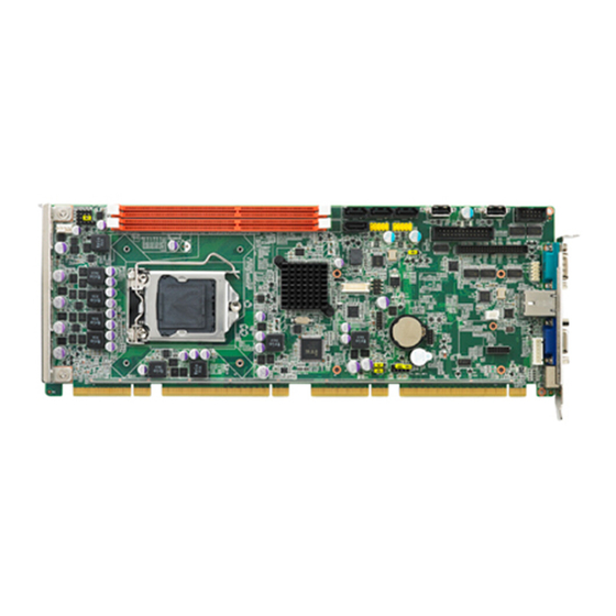
- Page 1 User Manual PCE-5026 LGA1155 ® ® Intel Core™i7/i5/i3/Pentium PICMG 1.3 System Host Board with DDR3 / SATA2.0 / USB2.0 / Single GbE LAN...
- Page 2 No part of this manual may be reproduced, copied, translated or transmitted in any form or by any means without the prior written permission of Advantech Co., Ltd. Information provided in this manual is intended to be accurate and reliable. How- ever, Advantech Co., Ltd.
-
Page 3: Declaration Of Conformity
Whether your new Advantech equipment is destined for the labo- ratory or the factory floor, you can be assured that your product will provide the reliability and ease of operation for which the name Advantech has come to be known. - Page 4 Memory Compatibility PCE-5026 Compatible Memory Brand Capacity Speed Type ECC Vendor PN Memory Advantech PN 1066 DDR3 N TS128MLK64V1U SEC K4B1G0846G‐BCH9 96D3‐1G1066NN‐TR 1066 DDR3 N TS256MLK64V1U SEC K4B1G0846G‐BCH9 96D3‐2G1066NN‐TR 1333 DDR3 N TS128MLK64V3U ELPIDA EDJ1108BFBG‐DJ‐F 96D3‐1G1333NN‐TR Transcend 1333 DDR3 N TS256MLK64V3U SEC K4B1G0846G‐BCH9 96D3‐2G1333NN‐TR4 1600 DDR3 N TS512MLK64V6N MICRON IUM22 D9PFJ...
-
Page 5: Processor Support
PCE-5026VG-00A1E Note! If PCE-5026 is used on different backplanes which have different PCIe configurations the message below will be displayed the first time the unit is powered on. The user has to turn off AC power and then turn it back on for PCIe re-configuration. - Page 6 It should be free of marks and scratches and in perfect working order upon receipt. As you unpack the PCE-5026, check it for signs of ship- ping damage. (For example, damaged box, scratches, dents, etc.) If it is damaged or it fails to meet the specifications, notify our service department or your local sales representative immediately.
-
Page 7: Table Of Contents
Table 1.2: Connectors ..............5 Board Layout: Jumper and Connector Locations........6 Figure 1.1 Jumper and Connector Locations....... 6 Block Diagram................... 7 Figure 1.2 PCE-5026 Block Diagram........... 7 Safety Precautions ..................7 Jumper Settings ..................8 1.8.1 How to Set Jumpers..............8 1.8.2... - Page 8 3.2.2 Advanced BIOS Features Setup..........28 Figure 3.3 Advanced BIOS Features Setup Screen....28 Figure 3.4 Advantech BIOS Update V1.3........29 Figure 3.5 PCI Subsystem Settings........... 30 Figure 3.6 PCI Express Settings ..........31 Figure 3.7 ACPI Settings ............32 Figure 3.8 Trust Computing............
- Page 9 HDD LED (JFP2 / HDDLED)..............78 Table B.12:HDD LED (JFP2 / HDDLED) ........78 B.13 ATX Soft Power Switch (JFP1 / PWR_SW) ..........79 Table B.13:ATX Soft Power Switch (JFP1 / PWR_SW) ..... 79 B.14 Hi-definition Audio Link Connector (HDAUD1)........79 PCE-5026 User Manual...
- Page 10 Table B.21:1 MB Memory Map ........... 84 B.22 PCI Bus Map................... 84 Table B.22:PCI Bus Map ............84 Appendix C Programming the GPIO ....85 Supported GPIO Register ............... 86 GPIO Registers..................86 GPIO Example Program-1 ..............86 PCE-5026 User Manual...
-
Page 11: Chapter 1 Hardware Configuration
Chapter Hardware Configuration... -
Page 12: Introduction
Introduction PCE-5026, id a PICMG 1.3 full size form-factor system host board, designed with an Intel® H61 PCH for industrial applications needing high computing power and strong I/O capability. PCE-5026 features either Intel® 22nm or 32nm manufacturing technol- ogy processors: Intel® Core™ i7/i5/i3 and Pentium® LGA1155. It comes with inte- grated memory and graphic controllers, supporting DDR3 1066/1333/1600* DRAM up to 16 GB (8GB per DIMM). -
Page 13: Specifications
1.3.2 Memory RAM: – PCE-5026: Up to 16 GB (8GB per DIMM) in two 240-pin DIMM sockets. Sup- ports dual-channel DDR3 1066/1333/1600* MHz SDRAM WITHOUT ECC function. Note! Wrong memory configuration may cause no boot or system instability problems. -
Page 14: Ethernet Lan
Board weight: 0.490 kg Jumpers and Connectors Connectors on the PCE-5026 system host board link it to external devices such as hard disk drives and a keyboard. In addition, the board has a number of jumpers used to configure the system for your application. -
Page 15: Table 1.2: Connectors
Serial ATA1 SATA2 Serial ATA2 SATA3 Serial ATA3 SATA4 Serial ATA4 CPU1 CPU Socket DIMMA1 Memory connector channel A DIMMB1 Memory connector channel B GPIO1 GPIO pin header (SMD pitch-2.0 mm) LPC1 COM port module expansion pin-header PCE-5026 User Manual... -
Page 16: Board Layout: Jumper And Connector Locations
Locations USB12 USB6 USB34 CPU FAN1 USB5 DIMMB1 DVI1 JFP1 3 optional SATA1~4 LPT1 LANLED1 JERP1 DIMMA1 COM2 COMD1 LAN1 VGA1 KBMS1 SPI_CN1 CPU1 GPIO1 LPC1 JCMOS1 AUDIO1 KBMS2 JCASE1 JIR1+JOBS1+JWDT1 Figure 1.1 Jumper and Connector Locations PCE-5026 User Manual... -
Page 17: Block Diagram
Block Diagram Figure 1.2 PCE-5026 Block Diagram Safety Precautions Warning! Always completely disconnect the power cord from your chassis when- ever you work with the hardware. Do not make connections while the power is on. Sensitive electronic components can be damaged by sud- den power surges. -
Page 18: Jumper Settings
1.8.2 BIOS CMOS (JCMOS1) The PCE-5026 CPU card contains a jumper that can erase BIOS CMOS resetting data about the system BIOS information. Normally this jumper should be set with pins 1-2 closed. If you want to reset data, set JCMOS1 to 2-3 closed for just a few seconds, and then move the jumper back to 1-2 closed. -
Page 19: Watchdog Timer Output (Jwdt1)
1.8.3 Watchdog Timer Output (JWDT1) The PCE-5026 contains a watchdog timer that will reset the CPU in the event the CPU stops processing. This feature means the PCE-5026 will recover from a soft- ware failure or an EMI problem. The JWDT1 jumper settings control the outcome of what the computer will do in the event the watchdog timer is triggered. -
Page 20: System Memory
System Memory PCE-5026 has two 240-pin memory sockets for Non-ECC DDR3 1066/1333/1600* memory modules with maximum capacity of 16 GB. (Maximum 8 GB for each DIMM) Note! PCE-5026 does NOT support registered DIMMs (RDIMMs). 1.10 Memory Installation Procedures To install DIMMs, first make sure the two handles of the DIMM socket are in the “open”... - Page 21 Remove the socket protection cap. Align the cuts on the processor with the edges of the socket. Replace the socket cap; lower the retainer bar and clip it shut. PCE-5026 User Manual...
-
Page 22: Processor Cooler Installation
CPU card: part number 1960047831N001. Buy it only for the PCE-5026 CPU card since it is NOT compatible with other brand CPU coolers (it is also not compatible with Intel boxed CPU cooler). -
Page 23: Chapter 2 Connecting Peripherals
Chapter Connecting Peripherals... -
Page 24: Introduction
LPT1. USB Ports (USB12, USB34, USB5, USB6) The PCE-5026 provides up to 6 USB (Universal Serial Bus) on-board ports with com- plete Plug & Play and hot swap support for up to 127 external devices. These USB ports comply with USB Specification 2.0, supporting transfer rates up to 480 Mbps (USB2.0). -
Page 25: Vga Connectors (Vga1)
Serial Ports (COMD1 & COM2) COM2 COMD1 The PCE-5026 offers two serial ports. These ports can connect to serial devices, such as a communication network device. The IRQ and address ranges for both ports are fixed. However, if you want to disable the port or change these parameters later, you can do this in the system BIOS setup. -
Page 26: Ps/2 Keyboard And Mouse Connector (Kbms1/Kbms2)
CPU Fan Connector (CPUFAN1) This connector supports cooling fans of 500 mA (6 W) or less, and it also supports smart fan control when using 4-pin or 3-pin cooler. CPUFAN1 PCE-5026 User Manual... -
Page 27: Front Panel Connectors (Jfp1, Jfp2 & Jfp3)
Front Panel Connectors (JFP1, JFP2 & JFP3) There are several external switches to monitor and control the PCE-5026. JFP1~3 2.8.1 ATX Soft Power Switch (JFP1) If your computer case is equipped with an ATX power supply, you should connect the power on/off button on your computer case to JFP1. -
Page 28: External Speaker (Jfp2)
2.8.4 External speaker (JFP2) JFP2 is a 4-pin connector for an external speaker. The PCE-5026 provides an onboard buzzer as an alternative to an external speaker. To enable the buzzer, set pins 3 and 4 as closed. JFP1 PWR_SW Reset... -
Page 29: H/W Monitor Alarm (Jobs1)
LAN Port (LAN1) LAN1 LED1 LED2 The PCE-5026 is equipped with one or two high-performance 1000 Mbps Ethernet LANs. They are supported by all major network operating systems. The RJ-45 jacks on the rear plate provide convenient connectivity. Table 2.2: LAN LED Indicators... -
Page 30: High Definition Audio Module Interface (Hdaud1)
Flash 10Mbps Link Off 2.11 High Definition Audio Module Interface (HDAUD1) HDAUD1 This HDAUD1 pin header is the connection interface to Advantech's 7.1 channel high definition audio module. Note! Advantech 7.1 channel high-definition audio module: PCA-AUDIO- HDA1E. PCE-5026 User Manual... -
Page 31: Figure 2.1 Jumper And Connector Locations Of Pca-Audio Hda1E
CPU card with the HD audio cable (PN:1701120251) Figure 2.1 Jumper and connector locations of PCA-AUDIO-HDA1E Note! Please remove the yellow jumper cap on the CPU card's HDAUD1 pin- header before connecting the HD audio cable to it. PCE-5026 User Manual... -
Page 32: Gpio Header (Gpio1)
Appendix C. 2.13 Case Open Connector (JCASE1) JCASE1 The 2-pin case open connector is for chassis with a case open sensor. When the case is open, the buzzer on motherboard will beep. PCE-5026 User Manual... -
Page 33: Front Panel Lan Indicator Connector (Lanled1)
LED2 1000Mbps Link On Green On 1000Mbps Active Green on Flash 1000Mbps Link Off 100Mbps Link On Orange On 100Mbps Active Orange On Flash 100Mbps Link Off 10Mbps Link On 10Mbps Active Flash 10Mbps Link Off LANLED1 PCE-5026 User Manual... -
Page 34: Serial Ata Interface (Sata1~Sata4)
When you install Linux OS, we recommend you to set AHCI mode in BIOS setting, otherwise the system may not recognize hard drives (using IDE mode) during Linux OS installation. 2.16 LPC Extension Interface (LPC1) LPC1 LPC1 is a 14-pin female pinheader for adopting for adopting Advantech LPC module. PCE-5026 User Manual... -
Page 35: Ami Bios Setup
Chapter AMI BIOS Setup... -
Page 36: Introduction
The Setup program uses a number of menus for making changes and turning the special features on or off. This chapter describes the basic navigation of the PCE-5026 setup screens. Figure 3.1 Setup Program Initial Screen... -
Page 37: Entering Setup
Date using the <Arrow> keys. Enter new values through the keyboard. Press the <Tab> key or the <Arrow> keys to move between fields. The date must be entered in MM/DD/YY format. The time must be entered in HH:MM:SS format. PCE-5026 User Manual... -
Page 38: Advanced Bios Features Setup
3.2.2 Advanced BIOS Features Setup Select the Advanced tab from the PCE-5026 setup screen to enter the Advanced BIOS Setup screen. You can select any of the items in the left frame of the screen, such as CPU Configuration, to go to the sub menu for that item. You can display an Advanced BIOS Setup option by highlighting it using the <Arrow>... -
Page 39: Figure 3.4 Advantech Bios Update V1.3
3.2.2.1 Advantech BIOS Update V1.3 Figure 3.4 Advantech BIOS Update V1.3 You can update BIOS via USB storage device in FAT32 format. Note! BIOS file name must be UPDATE.BIN. PCE-5026 User Manual... -
Page 40: Figure 3.5 Pci Subsystem Settings
Enable/Disable 64-bit capable devices to be decoded above 4G address space (only if system supports 64-bit PCI decoding). PCI Common Settings PCI Latency Timer Value to be programmed into PCI Latency Timer Register. VGA Palette Snoop Enables/Disables VGA palette registers snooping. PCE-5026 User Manual... -
Page 41: Figure 3.6 Pci Express Settings
Defines number of retry attempts software will take to retrain the link if previous training attempt was unsuccessful. Link Training Timeout Defines number of micro-seconds software will wait before polling “Link Train- ing” bit in link status register. Value range from 10 to 1000 uS. PCE-5026 User Manual... -
Page 42: Figure 3.7 Acpi Settings
Enable or disable Hibernate (OS/S4 Sleep State). This option may not be effec- tive with some OSs. Lock Legacy Resources Enable or Disable Lock Legacy Resources. PowerOn by Modem Enable or Disable Power On by Modem PCE-5026 User Manual... -
Page 43: Figure 3.8 Trust Computing
3.2.2.4 Trust Computing Figure 3.8 Trust Computing Security Device Support Enable or disable BIOS support for security device. You can purchase Advan- tech’s TPM (Trust Platform Module), PCA-TPM-00A1E, for your security device. PCE-5026 User Manual... -
Page 44: Figure 3.9 S5 Rtc Configuration
S5 RTC Wake Setting Figure 3.9 S5 RTC Configuration Wake System with Fixed Time Enable or disable system wake on alarm event, When enabled, system will wake on the hr:min:sec specified. 3.2.2.6 CPU Configuration Figure 3.10 CPU Configuration PCE-5026 User Manual... -
Page 45: Figure 3.11Sata Configuration
BIOS, two 64-byte cache lines are fetched into a 128-byte sector, regardless of whether the additional cache line has been requested or not. You may choose to enable or disable it. 3.2.2.7 SATA Configuration Figure 3.11 SATA Configuration PCE-5026 User Manual... -
Page 46: Figure 3.12Intel Trusted Execution Technology Configuration
Figure 3.12 Intel Trusted Execution Technology Configuration Intel Trusted Execution Technology Configuration This enables or disables Intel® Trusted Execution Technology. Note! Hardware platform should support Trust Platform Module (TPM1.2) to enable Intel Trusted Execution Technology. Advantech TPM module P/N: PCA-TPM-00A1E PCE-5026 User Manual... -
Page 47: Figure 3.13Usb Configuration
Device Reset Time-out Allows you to select the USB device reset time-out value. [1, 5,10, 20 sec] Device Power-up Delay This item appears only when you set the Device power-up delay item to [man- ual]. PCE-5026 User Manual... -
Page 48: Figure 3.14Smart Settings
3.2.2.10 Smart Settings Figure 3.14 Smart Settings Smart Self test Run SMART Self Test on all HDDs during POST. 3.2.2.11 Super I/O Configuration Figure 3.15 Super I/O Configuration PCE-5026 User Manual... -
Page 49: Figure 3.16Serial Port 1 Configuration
Figure 3.16 Serial Port 1 Configuration Figure 3.17 Serial Port 2 Configuration PCE-5026 User Manual... -
Page 50: Figure 3.18Parallel Configuration
Serial Port 1 -2 Configuration “Enable” or “Disable” Serial Port Note! Only serial port 2 can be configured to IrDA or ASKIR mode via BIOS setting menu. Parallel Port Configuration “Enable” or “Disable” Parallel Port PCE-5026 User Manual... -
Page 51: Figure 3.19Pc Health Status
ACPI Shutdown Temperature Use this to set the ACPI shutdown temperature threshold. When the system reaches the shutdown temperature, it will be automatically shut down by ACPI OS to protect the system from overheating damage. PCE-5026 User Manual... -
Page 52: Figure 3.20Cpu Ppm Configuration
Enable/Disable CPU C3 (ACPI C2) report to OS. CPU C6 Report Enable/Disable CPU C6 (ACPI C2) report to OS. CPU C7 Report Enable/Disable CPU C7 (ACPI C2) report to OS. ACPI T State Enable/Disable ACPI T state support PCE-5026 User Manual... -
Page 53: Chipset
3.2.3 Chipset Figure 3.21 Chipset 3.2.3.1 PCH-I/O Configuration Figure 3.22 PCH I/O Configuration LAN1 Controller Enable or Disable LAN1 Controller. PCE-5026 User Manual... -
Page 54: Figure 3.23Pci Express Configuration
Power Off, power On or Last State to restore AC power loss 3.2.3.2 PCI Express Configuration Figure 3.23 PCI Express Configuration Subtractive Decode Enable or disable PCI Express Subtractive Decode. PCI Express Configuration PCI Express Root Port 1 to 8 Setting. PCE-5026 User Manual... -
Page 55: Figure 3.24Usb Configuration
Control the USB EHCI(USB2.0) functions. One EHCI controller must always be enabled. EHCI2 Control the USB EHCI(USB2.0) functions. One EHCI controller must always be enabled. USB Ports Per-port Disable Control Control each of the USB ports disabling. PCE-5026 User Manual... -
Page 56: Figure 3.25Pch Azalia Configuration
3.2.3.4 PCH Azalia Configuration Figure 3.25 PCH Azalia Configuration Azalia Control detection of the Azalia device. Disable=Azalia will be disabled Enable=Azalia will be enabled Auto=Azalia will be enabled if present, disabled otherwise. PCE-5026 User Manual... -
Page 57: Figure 3.26System Agent (Sa) Configuration
3.2.3.5 System Agent (SA) Configuration Figure 3.26 System Agent (SA) Configuration VT-d Check to enable VT-d function on MCH PCE-5026 User Manual... -
Page 58: Figure 3.27Graphics Configuration
Select the video device which will be activated during POST. This has no effect if external graphics present. Secondary boot display selection will appear based on your selection. VGA modes will be supported only on primary display. Note: DOS mode only supports either VGA or DVI single output. PCE-5026 User Manual... -
Page 59: Figure 3.28Nb Pcie Configuration
Control ASPM support for the PEG: Device 1 Function 0. This has no effect if PEG is not the currently active device. Enable PEG Enable/Disable/Auto the PEG. De-emphasis Control Configure the De-emphasis control on PEG PCE-5026 User Manual... -
Page 60: Boot
3.2.3.8 Memory Configuration Overview of detailed memory information. Figure 3.29 Memory Information 3.2.4 Boot Figure 3.30 Boot PCE-5026 User Manual... -
Page 61: Security
Security Figure 3.31 Security Select Security Setup from the PCE-5026 Setup main BIOS setup menu. All Security Setup options, such as password protection and virus protection are described in this section. To access the sub menu for the following items, select the item and press <Enter>... -
Page 62: Save & Exit
Discard changes and Reset Select this option to quit Setup and reset computer without making any permanent changes to the system configuration. Save Changes Select this option to save your changes. Discard Changes Select this option to discard your changes. PCE-5026 User Manual... - Page 63 This option allows you to attempt to launch the EFI Shell application (shellx64.efi) from one of the available file system devices. *When you do some critical changes, the system will still reboot even you choose “Save changes and exit.” PCE-5026 User Manual...
- Page 64 PCE-5026 User Manual...
-
Page 65: Chipset Software Installation Utility
Chapter Chipset Software Installation Utility... -
Page 66: Before You Begin
To facilitate the installation of the enhanced display drivers and utility software, read the instructions in this chapter carefully. The drivers for the PCE-5026 are located on the software installation CD. The driver in the folder of the driver CD will guide and link you to the utilities and drivers under a Windows system. -
Page 67: Windows® Xp / Windows® 7 Driver Setup
Navigate to the “01-Chipset” folder and click “setup.exe” to com- plete the installation of the driver. Note! Wrong driver installation may cause unexpected system instability. The drivers on this CD support both Windows XP 32-bit /64-bit and Win- dows 7 32-bit/64-bit. PCE-5026 User Manual... - Page 68 PCE-5026 User Manual...
-
Page 69: Chapter 5 Integrated Graphic Device Setup
Chapter Integrated Graphic Device Setup... -
Page 70: Introduction
See Chapter 4 for information on installing the INF driver. Insert the Advantech driver DVD into your system and navigate to folder named “02_VGA” to choose proper operating system, then install driver by clicking “setup.exe” or “install.exe.”... -
Page 71: Lan Configuration
Chapter LAN Configuration... -
Page 72: Introduction
Introduction PCE-5026 features single Gigabit Ethernet via dedicated Intel 82579V which offers 500 Mbps bandwidth, eliminating the bottleneck of network data flow and incorporat- ing Gigabit Ethernet at 1000 Mbps. Features 10, 100, 1000 BASE-T IEEE 802.3 specification conformance. -
Page 73: Intel Me
Chapter Intel ME... -
Page 74: Introduction
“setup.exe” to complete the installation of the driver. Note! If the Intel® Management Engine (Intel® ME) driver has not been suc- cessfully installed, you may see an error on a “PCI Simple Communica- tions Controller” in Device Manager. PCE-5026 User Manual... -
Page 75: Appendix A Programming The Watchdog Timer
Appendix Programming the Watchdog Timer... -
Page 76: Introduction
Introduction The PCE-5026’s watchdog timer can be used to monitor system software operation and take corrective action if the software fails to function within the programmed period. This section describes the operation of the watchdog timer and how to pro- gram it. -
Page 77: Table A.1: Watchdog Timer Registers
Write 1 to bit 4: Watchdog timer count mode is 1000 times faster. If bit 3 is 0, the count mode is 1/1000 seconds mode. If bit 3 is 1, the count mode is 1/1000 minutes mode. PCE-5026 User Manual... -
Page 78: Example Program
; Enable the function of watchdog timer al,30h dx,al al,dx al,03h dx,al ;----------------------------------------------------------- Dec dx ; Set second as counting unit al,0f5h dx,al al,dx And al,not 08h dx,al ;----------------------------------------------------------- Dec dx ; Set timeout interval as 10 seconds and start counting PCE-5026 User Manual... - Page 79 ;----------------------------------------------------------- Dec dx ; Set minute as counting unit al,0f5h dx,al al,dx al,08h dx,al ;----------------------------------------------------------- Dec dx ; Set timeout interval as 5 minutes and start counting al,0f6h dx,al al,5 ; 5 minutes dx,al PCE-5026 User Manual...
- Page 80 ; Enable watchdog timer to be reset by mouse al,0f7h dx,al al,dx al,80h dx,al ;----------------------------------------------------------- Dec dx ; Lock NCT6776F al,0aah dx,al Enable watchdog timer to be reset by keyboard ;----------------------------------------------------------- Mov dx,2eh ; Unlock NCT6776F Mov al,87h Out dx,al Out dx,al ;----------------------------------------------------------- PCE-5026 User Manual...
- Page 81 Mov dx,2eh ; Unlock NCT6776F Mov al,87h Out dx,al Out dx,al ;----------------------------------------------------------- Mov al,07h ; Select registers of watchdog timer dx,al al,08h dx,al ;----------------------------------------------------------- Dec dx ; Enable the function of watchdog timer al,30h dx,al al,03h dx,al ;----------------------------------------------------------- PCE-5026 User Manual...
- Page 82 Dec dx ; Generate a time-out signal al,0f7h dx,al ;Write 1 to bit 5 of F7 register al,dx al,20h dx,al ;----------------------------------------------------------- Dec dx ; Lock NCT6776F al,0aah dx,al PCE-5026 User Manual...
-
Page 83: Appendix B I/O Pin Assignments
Appendix I/O Pin Assignments... -
Page 84: Parallel Port Connector (Lpt1)
Parallel Port Connector (LPT1) Table B.1: Parallel port Connector (LPT1) Signal Signal STROBE* AUTOFD* INIT* SLCTINI* ACK* BUSY SLCT No pin * low active VGA Connector (VGA1) Table B.2: VGA Connector (VGA1) Signal Signal GREEN BLUE H-SYNC V-SYNC PCE-5026 User Manual... -
Page 85: Rs-232 Seral Port (Comd1)
RS-232 Seral Port (COMD1) Table B.3: COM Connector (COMD1) Signal SOUT RS-232 Serial Port (COM2) Table B.4: RS-232 Serial Port (COM2) Signal SOUT PCE-5026 User Manual... -
Page 86: Usb 2.0 Header (Usb12 & Usb34)
USB 2.0 Header (USB12 & USB34) Table B.5: USB Header (USB12 & USB34) Signal Signal USB1_VCC5 USB2_D+ USB2_VCC5 USB1_D- USB2_D- No pin USB1_D+ PS/2 Keyboard/Mouse Connector (KBMS1) Table B.6: PS/2 Keyboard/Mouse Connector (KBMS1) Signal KB DATA MS DATA KB CLOCK MS CLOCK PCE-5026 User Manual... -
Page 87: External Keyboard Connector (Kbms2)
Table B.8: CPU Fan Power Connector (CPUFAN1) Signal +12V Detect Power LED and Keyboard Lock Connector (JFP3 / PWR_LED & KEY LOCK) Table B.9: Power LED and Keyboard Lock Connector (JFP3 / PWR_LED & KEY LOCK) Signal LED power (+3.3 V) KEYLOCK# PCE-5026 User Manual... -
Page 88: External Speaker Connector (Jfp2 / Speaker)
SPK_CN17P2 SPK_CN17P3 SPK_CN17P4 B.11 Reset Connector (JFP1 / RESET) Table B.11: Reset Connector (JFP1 / RESET) Signal RESET # B.12 HDD LED (JFP2 / HDDLED) Table B.12: HDD LED (JFP2 / HDDLED) Signal HDD LED SATA LED PCE-5026 User Manual... -
Page 89: Atx Soft Power Switch (Jfp1 / Pwr_Sw)
Hi-definition Audio Link Connector (HDAUD1) Table B.14: Hi-Definition Audio Link Connector (HDAUD1) Signal Signal ACZ_VCC ACZ_SYNC ACZ_BITCLK ACZ_SDOUT ACZ_SDIN0 ACZ_SDIN1 ACZ_RST ACZ_12V B.15 SM Bus Connector (JFP2 / SNMP) Table B.15: SM Bus Connector (JFP2 / SNMP) Signal SMB_DATA SMB_CLK PCE-5026 User Manual... -
Page 90: Lan1 Led Connector (Lanled1)
B.16 LAN1 LED Connector (LANLED1) Table B.16: LAN1 LED Connector (LANLED1) Signal #LAN1_ACT V33_AUX #LAN1_LINK1000 #LAN1_LINK100 V33_AUX B.17 GPIO Header (GPIO1) Table B.17: GPIO Header (GPIO1) Signal SIO_GPIO0 SIO_GPIO4 SIO_GPIO1 SIO_GPIO5 SIO_GPIO2 SIO_GPIO6 SIO_GPIO3 SIO_GPIO7 VCC_GPIO PCE-5026 User Manual... -
Page 91: Fixed I/O Ranges Decoded By Intel Pch
RTC Controller RTC Controller RTC Controller DMA Controller, LPC, DMA Controller, LPC, PCI, or PCIe PCI, or PCIe DMA Controller DMA Controller 81h-83h DMA Controller and DMA Controller 84h-86h LPC, PCI, or PCIe DMA Controller DMA Controller PCE-5026 User Manual... - Page 92 SATA Controller, PCI, SATA Controller, PCI, 376h SATA or PCIe or PCIe SATA Controller, PCI, SATA Controller, PCI, 3F6h SATA or PCIe or PCIe Interrupt Controller Interrupt Controller Interrupt 4D0h-4D1h CF9h Reset Generator Reset Generator Processor I/F PCE-5026 User Manual...
-
Page 93: System I/O Ports
Available IRQ6 Available IRQ7 LPT1 IRQ8 System COMS/Real-time clock IRQ9 SCI IRQ IRQ10 Communication port (COM3-6) for PCA-COM232 module IRQ11 Communication port (COM8-11) for PCA-COM485 module IRQ12 PS/2 mouse IRQ13 Numeric data processor IRQ14 Available IRQ15 Available PCE-5026 User Manual... -
Page 94: Mb Memory Map
PCI Slot 2 AD30 INT C, D, A, B GNT B REQ B PCI Slot 3 AD29 INT D, A, B, C GNT C REQ C PCI Slot 4 AD28 INT A, B, C, D GNT D REQ D PCE-5026 User Manual... -
Page 95: Appendix C Programming The Gpio
Appendix Programming the GPIO... -
Page 96: Supported Gpio Register
Enter the extended function mode, interruptible double-write ------------------------------------------------ MOV DX,2EH MOV AL,87H OUT DX,AL OUT DX,AL -------------------------------------------------------------- Configure logical device, configuration register CRE0,CRE1,CRE2 -------------------------------------------------------------- MOV DX,2EH MOV AL,09H OUT DX,AC DEC DX MOV AL,30H OUT DX,AL INC DX IN AL,DX OR AL,10000000B PCE-5026 User Manual... - Page 97 ;Set GPIO is normal not inverter OUT DX,AL; DEC DX MOV AL,E1H OUT DX,AL INC DX MOV AL,??H ; Put the output value into AL OUT DX,AL ------------------------------------------ Exit extended function mode | ------------------------------------------ MOV DX,2EH MOV AL,AAH OUT DX,AL PCE-5026 User Manual...
- Page 98 No part of this publication may be reproduced in any form or by any means, electronic, photocopying, recording or otherwise, without prior written permis- sion of the publisher. All brand and product names are trademarks or registered trademarks of their respective companies. © Advantech Co., Ltd. 2012...
Need help?
Do you have a question about the PCE-5026 and is the answer not in the manual?
Questions and answers