Table of Contents
Advertisement
Quick Links
EKEVO 6/N6 L-E / L-EF3
EKEVO 7/N7 L-E / L-EF3
EKEVO 8/N8 L-E / L-EF3
EKEVO 9/N9 L-E / L-EUF
Original Operating Instructions
For authorised specialist engineers
Fuel-oil burner
de ................................................... 4200 1089 7500
fr ..................................................... 4200 1089 7600
it ..................................................... 4200 1089 7700
nl .................................................... 4200 1089 7800
EKEVO 6, EKEVO 7 L-E
EKEVO 8, EKEVO 9 L-E
EKEVO 6, EKEVO 7 L-EF3 4200 1073 8000
EKEVO 8, EKEVO 9 L-EUF 4200 1073 7800
N6/N7 L-E
EKEVO 6, EKEVO 7 L-E
EKEVO 8, EKEVO 9 L-E
EKEVO 6, EKEVO 7 L-EF3 4200 1089 9200
EKEVO 9 L-EUF
N6/N7 L-E
EKEVO 6, EKEVO 7 L-E
EKEVO 8, EKEVO 9 L-E
EKEVO 6,7,8,9 L-EF3
EKEVO 9 L-EUF
04/2019 - Art. Nr. 4200 1089 7900A
4200 1054 2800
N6/N7 L-EF3
4200 1073 7400
N8/N9 L-E
N8/N9 L-EF3
N9 L-EUF
4200 1045 0401
4200 1089 9000
N6/N7 L-EF3
4200 1089 9100
N8/N9 L-E
N8/N9 L-EF3
4200 1089 9300
N9 L-EUF
4200 1095 6600
4201 1023 4800
N6/N7 L-E
4201 1023 5000
N6/N7 L-EF3
4201 1023 4900
N8/N9 L-E
4201 1023 5200
N8/N9 L-EF3, N9 L-EUF
4200 1044 9701
4200 1052 0100
4200 1052 7300
4200 1052 7100
4200 1095 6800
4200 1095 6700
4200 1095 6900
4200 1095 7000
14 064 890
14 064 901
14 071 787
14 071 798
Advertisement
Table of Contents

Related Manuals for elco EKEVO 6 L-E


Summary of Contents for elco EKEVO 6 L-E
- Page 1 EKEVO 6/N6 L-E / L-EF3 EKEVO 7/N7 L-E / L-EF3 EKEVO 8/N8 L-E / L-EF3 EKEVO 9/N9 L-E / L-EUF Original Operating Instructions For authorised specialist engineers Fuel-oil burner de ........... 4200 1089 7500 fr ............. 4200 1089 7600 it ............. 4200 1089 7700 nl ............
-
Page 2: Table Of Contents
General information Contents General information Contents ..............................2 Important information..........................3 Burner description ..........................4-5 Installation Air duct connection, Rotating air box ...................... 6 General information regarding burner installation .................. 7 Boiler lining for L-E, L-EF3 et L-EUF burner................... 8 Burner installation ........................... -
Page 3: Important Information
Any other type of application requires the approval of Safety measures Installation location ELCO. The burner may only be used in The burner must not be operated in The burner and accessories must be accordance with the instructions set out rooms with aggressive vapours (e.g. -
Page 4: Burner Description
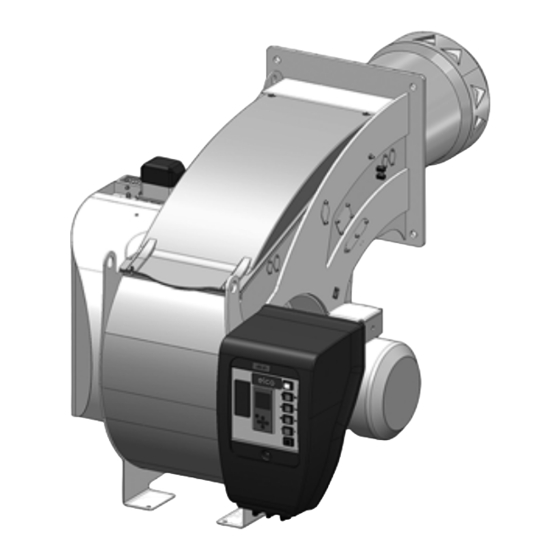
General information N6/N7/N8/N9 Burner description Power controller (option) Casing Burner tube Integrated switch cabinet Burner flange Air box Lifting rings (underneath the metal cover for the N8 burner) Connection cooling sight glass Air pressure switch Electric motor Y10 Actuator for air and fuel-oil flow regulator 102 Pump Note:... - Page 5 102 Pump Note: The construction principle for EKEVO 6 - EKEVO 9 L-E burners is largely identical. To provide an example, only the scenario with burner EKEVO 6 L-E is shown on this page. 04/2019 - Art. Nr. 4200 1089 7900A...
-
Page 6: Installation Air Duct Connection, Rotating Air Box
Installation EKEVO 6/EKEVO 7/EKEVO 8/EKEVO 9 Air duct connection Rotating air box EKEVO 6/EKEVO 7 EKEVO 6/EKEVO 7 for dimensions: see technical data EKEVO 8/EKEVO 9 EKEVO 8/EKEVO 9 for dimensions: see technical data * Rotation procedure of air box: see chapter «Servicing»... -
Page 7: General Information Regarding Burner Installation
Installation General information regarding burner installation Tightening torques During installation, commissioning and maintenance, the following torques for screw connections must be observed. Recommended tightening torques Standard unions N.B.: In general, the correct tightening torques have been applied when the unions are tightened hand-tight using a screwdriver (ISO 272) or angled Allen key. -
Page 8: Boiler Lining For L-E, L-Ef3 Et L-Euf Burner
Installation Boiler lining for L-E, L-EF3 und L-EUF burner Boiler lining N6-N8 L-E / EKEVO 6-EKEVO 8 L-E The burner lining must be installed at a right angle to the burner tube. Possible trimming work (bevelling, rounding) as required for reverse boilers, for example, should done at a diameter not below 70% of the combustion chamber diameter. -
Page 9: Burner Installation
Installation Burner installation Burner flange seal (option 1) thermocord, the operator should wear The surface of the The sealing tape in the accessories kit loose-fitting, long-sleeved clothing. In Seal corners with entire circumference sealing tape must be affixed to the burner as shown the event of high fibre dust must be sealed in the drawing below. -
Page 10: Combustion Components
Installation Combustion components Combustion components N/EKEVO 6/7 L-E adjustment data/check G (mm) Burner A (mm) B (mm) C (mm) D (mm) E (mm) F (mm) H (mm) min. max. N/EKEVO 6.2400 N/EKEVO 6.2900 N/EKEVO 7.3600 N/EKEVO 7.4500 04/2019 - Art. Nr. 4200 1089 7900A... -
Page 11: Combustion Components N/Ekevo 8 L-E Adjustment Data/Check
Installation Combustion components Combustion components N/EKEVO 8 L-E adjustment data/check EKEVO/N8.5800 EKEVO/N8.7100 04/2019 - Art. Nr. 4200 1089 7900A... -
Page 12: Combustion Components N/Ekevo 9 L-E Adjustment Data/Check
Installation Combustion components Combustion components N/EKEVO 9 L-E adjustment data/check EKEVO/N9.8700 EKEVO/N9.10400 04/2019 - Art. Nr. 4200 1089 7900A... -
Page 13: Combustion Components N/Ekevo 6 - N/Ekevo 9 L-E/L-Ef3/L-Euf Adjustment Data/Check
Installation Combustion components Combustion components N/EKEVO 6 - N/EKEVO 9 L-E/L-EF3/L-EUF adjustment data/check Burner Burner N/EKEVO 6.2400 L-EF3 N/EKEVO 6.2400 L-EF3 15-18 N/EKEVO 6.2900 L-EF3 N/EKEVO 6.2900 L-EF3 15-18 N/EKEVO 7.3600 L-EF3 N/EKEVO 7.3600 L-EF3 15-18 N/EKEVO 7.4500 L-EF3 N/EKEVO 7.4500 L-EF3 15-18 N/EKEVO 8.5700 L-EF3 N/EKEVO 8.5700 L-EF3... -
Page 14: Ignition Electrodes N/Ekevo 6 - N/Ekevo 9 L-E/L-Ef3/L-Euf Adjustment Data/Check
Installation Combustion components Ignition electrodes N/EKEVO 6 - N/EKEVO 9 L-E/L-EF3/L-EUF adjustment data/check Note: If there are any ignition or flame detection problems, check the setting and dimensions of the electrodes. If the wear is too great, replace the electrodes. N/EKEVO 6 - N/EKEVO 9 L-EF3 N/EKEVO 6/7 L-E Burner... - Page 15 Installation Combustion components Ignition electrodes N/EKEVO 6 - N/EKEVO 9 L-E/L-EF3/L-EUF adjustment data/check Burner Ø A [mm] B [mm] C [mm] G [mm] H [mm] J [mm] K [mm] N/EKEVO 2,5... 3 62,7 16,9 94,8 12,5 12,5 8 L-E N/EKEVO 2,5...
-
Page 16: Installation
Installation Combustion components Installation Installing the combustion components • Check the settings for the ignition electrode and the combustion components as shown. • Insert the combustion components into the flame tube, tighten the securing screws S3. • Connect the oil supply (fast-closing couplings). -
Page 17: Air Pressure Switch
Installation Air pressure switch Air pressure switch in other important gas consumption The air pressure switch is provided for countries. monitoring the pressure of the N.B.(Gas and air pressure switches) combustion air fan. Pressure switch The pressure switches must be set in LGW... -
Page 18: Hydraulics
Hydraulics Fuel-oil system diagram With booster pump Forced draught burner Fuel-oil filter Shut-off valve Oil level indicator Intake valve Tank Leak warning device Fast-closing valve Fill pipe Limit value encoder Vent line Pump installation Pressure maintaining valve Direct suction Forced draught burner Fast-closing valve Fuel-oil filter Fill pipe... -
Page 19: General Information Regarding The Fuel-Oil System
Hydraulics General information regarding the fuel-oil system Fuel-oil hydraulics diagram Air pressure switch N6, N7 Fan motor 119 Pressure tap 120 Air flap 143 Manometer with shut-off valve (141) 174 Ventilator 349 Actuator Oil ignition transformer Pump motor Y16 Fuel-oil safety valve, supply Y18 Fuel-oil safety valve, return 105 Fuel-oil hose 110 Fuel-oil nozzles... - Page 20 Hydraulics General information regarding the fuel-oil system Fuel-oil hydraulics diagram Pump motor N8, N9 Y16 Fuel-oil safety valve, supply Y18 Fuel-oil safety valve, return 143 Manometer with shut-off valve (option) 175 Fuel-oil filter 176 Fuel-oil pump 187 Pressure regulation valve (integrated in pump) 188 Fuel-oil hydraulic block 200 Measuring point fuel oil suction...
- Page 21 Hydraulics General information regarding the fuel-oil system Fuel-oil hydraulics diagram Pump motor EKEVO 8,9 Y16 Fuel-oil safety valve, supply Y18 Fuel-oil safety valve, return 141 Pump input pressure measuring point 143 Manometer with shut-off valve (141) (option) 175 Fuel-oil filter 176 Fuel-oil pump 311 Fuel-oil pressure switch, return (max.)
-
Page 22: Fuel-Oil Pressure Switch
Hydraulics Fuel-oil pressure switch Fuel-oil pressure switch 3 bar. The set shut-off pressure should Fuel-oil pressure switches are used to also take the switching differential into monitor burners to ensure that they do consideration. not exceed or fall below specific fuel-oil When the setting procedure is complete, pressures. -
Page 23: General Information Regarding The Fuel-Oil System
Hydraulics General information regarding the fuel-oil system Fuel-oil connection Venting Hoses are used to make a connection to With the ring line, if any, in operation, the fuel-oil tubes or the gate valves. To open the supply line and return gate prevent kinks and therefore any risk of valves. -
Page 24: Pump Type Ta
Hydraulics Pump type TA Areas of application Pumping capacity Capacity (l/hr) - Domestic oil and heavy-grade oil. - Two-line system. Description of functions The gearbox draws the fuel-oil from the tank and supplies it under pressure to the valve which controls the oil pressure for the nozzle line. - Page 25 Hydraulics Pump type TA General Attachment Flange attachment Connections Cylindrical in acc. with ISO 228/1 Supply line and return G 1/2 Nozzle outlet G 1/2 Pressure test connection G 1/4 Vacuum test connection G 1/4 Shaft Ø 12 mm Bypass-plug Used in the vacuum connection for two-line installation Weight...
-
Page 26: Commissioning Fuel-Oil Hydraulic Block
Commissioning Fuel-oil hydraulic block When replacing the solenoid valves during servicing, ensure that the right valve type is fitted the right way round. The solenoid valve in the supply line (type 321 F 2523) must be fitted so that the flow direction punched on the valve flange is the same as the flow direction of the oil (from the pump to the nozzle rods). -
Page 27: Return Nozzle Rod Rdn
Commissioning Return nozzle rod RDN Return nozzle rod RDN Stroke setting (control needle) Hydraulic piston system Fuel-oil connection, return Fuel-oil connection, supply Return nozzle fluidics W-50° Please note: Description needle head. If the pump pressure is too The stroke (1) is set at the factory, The return nozzle rod RDN is suitable for little (<... -
Page 28: Nozzle Selection, Type W1 - 50
Commissioning Nozzle selection, type W1 - 50° Return nozzle Fluidics nozzle W1 is a return nozzle with integral, spring-loaded stop needle. The flow is regulated by changing the return pressure, while the supply pressure is held constant. Before commissioning, the nozzle size must be compared with the output conveyed. -
Page 29: Nozzle Selection, Type W1 - 45
Commissioning Nozzle selection, type W1 - 45° Return nozzle Depending on burner size and the furnaces concerned, it may be possible to use Fluidics nozzles W1 with a spray angle of 45°. The correct nozzle is selected as appropriate to the combustion chamber delivered with the burner. -
Page 30: Allocation Of Nozzle - W1 - 45°/50
Commissioning Allocation of nozzle - W1 - 45°/50° Supply pressure 25 / 28 bar Size of the control shaft ~Maximum power ~Maximum power with a maximum pressure Fluidics fuel oil nozzle 25 bar 28 bar of 2 bar in the circulation loop Fluidics W1 100 1300... -
Page 31: Nozzle Selection, Type W2 - 45°/50
Commissioning Nozzle selection, type W2 - 45°/50° Return nozzle Fluidics nozzle W is a return nozzle with integral, spring-loaded stop needle. The flow is regulated by changing the return pressure, while the supply pressure is held constant. Before commissioning, the nozzle size must be compared with the output conveyed. -
Page 32: Allocation Of Nozzle - W2 - 45°/50
Commissioning Allocation of nozzle - W2 - 45°/50° Supply pressure 25 / 28 bar ~Maximum power ~Maximum power Regulation spindle size Fluidics fuel oil nozzle 25 bar 28 bar Pressure in the loop pipe 2 bar max. Fluidics W2 100 1150 1250 Fluidics W2 115... -
Page 33: M14 Nozzle Adapter Nozzle Selection - Sonic Model
Commissioning M14 nozzle adapter Nozzle selection - Sonic model Only L-EF3: To use the burner with inverted combustion chambers, Sonic nozzles with a spray angle of 45° can be used. A special adapter is required in order to fit this model into the nozzle rod (see illustration). -
Page 34: Return Nozzle Rod Rdg
Commissioning Return nozzle rod RDG 1 Nozzle head 2 Slide 3 Pressure spring, supply 4 Thrust rod 5 Sealing cone, return 6 Sealing ring, supply 7 Pressure channel Stroke H = 9 mm Return piston opens at approx. 13 bar; fully open at approx. -
Page 35: Nozzle Selection, Type Sonic 60
Commissioning Nozzle selection, type Sonic 60° Diagram - Sonic-Spray DZ 1000-60° return nozzle with regulated return. extra-light fuel-oil Supply pressure 28 bar. Return pressure at the hydraulic block [bar] The Sonic-Spray return nozzle is Preference should be given to the use of available from the supplier with various 45°... -
Page 36: Allocation Of Nozzle - Sonic 60
Commissioning Allocation of nozzle - Sonic 60° Supply pressure 25 / 28 bar Size of the control shaft ~Maximum power ~Maximum power with a maximum pressure Sonic fuel oil nozzle 25 bar 28 bar of 2 bar in the circulation loop Sonic 160kg-60°... -
Page 37: Nozzle Selection, Type Sonic 45
Commissioning Nozzle selection, type Sonic 45° Diagram - Sonic-Spray DZ 1000-45° return nozzle with regulated return. Fuel: domestic fuel-oil, Supply pressure 28 bar. Return pressure at the hydraulic block [bar] The Sonic-Spray return nozzle is Preference should be given to the use of available from the supplier with various 45°... -
Page 38: Allocation Of Nozzle - Sonic 45
Commissioning Allocation of nozzle - Sonic 45° Supply pressure 25 / 28 bar Size of the control shaft ~Maximum power ~Maximum power with a maximum pressure Sonic fuel oil nozzle 25 bar 28 bar of 2 bar in the circulation loop Sonic 140kg-45°... -
Page 39: Electronic Burner Controller
Commissioning Electronic burner controller Description The electronic burner controller is a programmable automatic firing device with an integrated electronic compound controller. There may be additional functions, depending on the equipment and model. The following burner-specific controllers are used. Burner controller BT 320 BT 330 Manufacturer... -
Page 40: Electrical Cabinet Door Layout
Commissioning Switch cabinet door layout Manual terminal for controlling the burner control unit NEXTRON Switch / light indicator control voltage Power control +/- Manual / Automatic switch Local - 0 REMOTE switch Power controller (option) EKEVO Note: The above information is for standard equipment. -
Page 41: Servomotor Ste
Commissioning Servomotor STE Servomotor STM 40 The BT300 electronic control system works with the STE4.5 numerically controlled servomotor. For monitoring the function and direction of rotation, there is a driver with digital feedback via encoder disc. Observe the commissioning procedure for BT300. -
Page 42: Servomotor Lamtec 6 / 16 Nm
Commissioning Lamtec 6 / 16 Nm servomotor Technical data 6 Nm: Voltage: 230 V AC Frequency: 50 Hz Angle of rotation: 90° Running time: 60 sec. for 90° Nominal torque: 6 Nm Static holding moment: 4,5 Nm Dimensions (W x H x D): 101 mm x 117 mm x 170,5 mm Potentiometer (fitted): 5 k... -
Page 43: Flame Sensor
Commissioning Flame sensor The flame sensor is a component of the Depending on the requirements of the In some gas burners, flame monitoring flame monitoring system. burner and fuels, the flame sensor may is achieved by means of ionisation. In be an optical sensor that monitors light this case, no optical flame sensor is In interaction with the automatic... - Page 44 Commissioning Flame sensor Table: cell setting Burner FFS08 (IR) QRA 2 A [mm] Angle α [°] A [mm] Angle α [°] A [mm] Angle α [°] N/EKEVO 6 Standard N/EKEVO 7 L-E Standard N/EKEVO 7 L-EF3 Standard N/EKEVO 8-9 Standard EKEVO 6/7 N/EKEVO 8/9 Burner...
-
Page 45: Electrical Connection Checks Before Commissioning
Commissioning Electrical connection Checks before commissioning All electrical installation and Before working on electrical connection work must only be carried components, switch off the electricity out by a suitably qualified electrician. supply via an omnipolar cut-off switch. N.B.: The applicable Check that the power supply is guidelines and directives completely off and take all safety... -
Page 46: Fuel-Air Compound Control
Commissioning Fuel-air compound control Fuel-air compound control Proceed in accordance with the Equipment option: This compound pneumatic control commissioning instructions for the control system with precision-adjustment electronic compound control system To improve the efficiency of the system, capability has been designed to allow when making gradual adjustments to the combustion manager can be the fuel and air flow rates to be steadily... -
Page 47: Burner Power Adjusting Sequence
Commissioning Burner power adjusting sequence The burner is operated and adjusted Adjusting sequence Please note: using a handheld device or a PC (serial (Short description) If changes are made to the primary gas interface). • Switch on burner (switch on control pressure, test all burner power settings. -
Page 48: Inspection
Commissioning Inspection Before commissioning the system for Fuel-oil commissioning the first time, the following inspections must be carried out: Open all the gate valves on the fuel-oil supply system. • Observe the operating instructions of • Set the fuel selection via remote the boiler manufacturer. -
Page 49: Preventilation
Commissioning Preventilation Preventilation: Assuming the conditions in the area or Please note: the boiler unit in the case of electronic Care must be taken to ensure that the are the same for preventilation and compound controls (BT300/ boiler system is adequately preventilated. -
Page 50: Fuel-Oil Start-Up Mode, Fuel-Oil Operating Mode
Commissioning Fuel-oil start-up mode Fuel-oil operating mode General safety functions Fuel-oil start-up mode The solenoid valves open and release be closed when the burner is in its off If heat is required by the furnace, the position so as to prevent cold air from the oil, which is under pressure, to the electronic combustion manager flowing through the burner, heat... -
Page 51: Servicing Maintenance
Servicing Maintenance Burner and boiler servicing must only - Check the ignition electrodes and stage to avoid greater consequential be carried out by a professionally ignition sparking. Clean and readjust if damage. Listen to the motor bearing qualified heating engineer. The necessary noise to identify possible irregularities. -
Page 52: Maintenance Replacing The Control Unit
Servicing Maintenance Replacing the control unit Warning! parts. Using defective or damaged com- tion, and may even cause injury (risks of Replace any damaged or defective com- ponents may cause malfunctioning and serious or fatal injury). ponents! Replace safety components hazardous operation. - Page 53 Servicing Maintenance Checking the combustion N8/N9 N6/N7 components • N6/N7: Unscrew the 2 screws S, remove the burner cover. • N8/N9: Live the front end of the burner and remove rearwardly. • EKEVO : Unscrew the 6 screws W, remove the housing cover. •...
-
Page 54: Maintenance, Checking / Installing The Combustion Components
Servicing Maintenance Checking / installing the combustion components Cleaning the cover Checking the flue gas temperature • Check the flue gas temperature at • Do not use abrasive products or Important regular intervals. products containing chlorine. After every operation: check the •... -
Page 55: Rotation Procedure Of Air Box Ekevo 6/Ekevo 7
Servicing EKEVO 6/EKEVO 7 Rotation procedure of air box Rotation procedure of air box Remove the flexible air hose. Disassemble the servomotor from the air flap and fasten it to the casing. Disassemble the cover of the air box. Unfasten the air box support, swing it towards the new desired position and fasten it again (rotation possible in 45°... -
Page 56: Rotation Procedure Of Air Box Ekevo 8/Ekevo 9
Servicing EKEVO 8/EKEVO 9 Rotation procedure of air box Installation instructions for air box rotation on the burner By default the air box opening on the EK EVO is pointing in the direction of the boiler. However, if an air duct connection is provided, it is possible to orient the air box, with certain adjustments, in the direction of this duct. - Page 57 Servicing EKEVO 8/EKEVO 9 Rotation procedure of air box 6. Removing and rotating the air box closed. The drive can then be coupled to support the air flap shaft. Retighten the screws Before you can orient the air box in the on the coupling.
- Page 58 Servicing EKEVO 8/EKEVO 9 Rotation procedure of air box Figure Wiring adjustment Air pressure switch pressure tap Basic position Pos. A as basic position 45° Pos. A 3 additional adhesive attachment flanges on burner feet 90° Pos. A 3 additional adhesive attachment flanges on burner feet 135°...
-
Page 59: Fan Wheel Setting N6/N7/N8/N9 - Ekevo 6/7/8/9
1 - Blow turbine 2 - Air conveyor Burner Burner [mm] [mm] N/EKEVO 6 L-E N/EKEVO 6 L-EF3 N/EKEVO 7.3600 L-E N/EKEVO 7.3600 L-EF3 N/EKEVO 7.4500 L-E N/EKEVO 7.4500 L-EF3 N/EKEVO 8.5800 L-E N/EKEVO 8.5700 L-EF3 N/EKEVO 8.7100 L-E... -
Page 60: Fan Wheel Setting Ekevo 6/7
Servicing Fan wheel setting EKEVO 6/7 Because of its design the turbine can be fitted to the drive shaft only in a fixed position. The same position is consequently ensured every time it is assembled. There is no need for any further adjustment of the axial cover through the air conveyor. -
Page 61: Exhaust Gas Measurement
Servicing Exhaust gas measurements Exhaust gas measurement the permissible smoke spot number in the Gas temperature 15 °C In order to ensure efficient and fault-free exhaust gas must not be exceeded. Standard pressure 1013 mbar operation, the burner must be adjusted with Calculating the volumetric flow rate for reference to the specific system. -
Page 62: Diagnosing And Remedying Faults
Servicing Exhaust gas measurements Diagnosing and remedying faults Exhaust gas loss Natural Town Exhaust gas loss by way of free heat will Fuel-oil EL Fuel-oil S Liquid gas occur as a result of the temperature difference between the fuel-air mixture 0.50 0.490 0.370... - Page 63 Servicing Diagnosing and remedying faults 8. Cleaning and lubricating 4. Nozzle - uneven 6. Combustion components - instructions atomisation poor combustion values Depending on the cleanliness status of heavy internal oil deposits the combustion air, the fan impeller, Cause Remedy or heavy coke deposits ignition electrodes, flame sensors and (fuel-oil mode)
-
Page 64: Faults
Servicing Faults • According to DIN 4788, components If system faults occur, proceed with The start-up program will be initiated checking the basic conditions for with technical safety-related and should be carefully monitored. proper operation of the system. functions may not be repaired. On The possible cause of the fault may be the other hand, they may be quickly found by referring to the fault... -
Page 65: Manufacturer Certification In Accordance With 1. Bimschv
04/2019 - Art. Nr. 4200 1089 7900A... - Page 66 04/2019 - Art. Nr. 4200 1089 7900A...
- Page 67 04/2019 - Art. Nr. 4200 1089 7900A...
- Page 68 Made in the EU. Non contractual document. 04/2019 - Art. Nr. 4200 1089 7900A...
Need help?
Do you have a question about the EKEVO 6 L-E and is the answer not in the manual?
Questions and answers