Table of Contents
Advertisement
VG5.950 M(V)/TC (/PED)
VG5.1200 M(V)/TC (/PED)
All manuals and user guides at all-guides.com
Original operating instructions
For authorised specialist engineers
Gas burners
de, fr................................. 4200 1041 0903
it, nl.................................. 4200 1041 1003
en..................................... 4200 1041 1103
de, fr, it, nl, en................. 4200 1041 0803
VG5 M/TC (PED) 4201 1006 6900
VG5 MV/TC (PED) 4201 1016 9500
......................................... 4200 1060 1202
06/2016 - Art. Nr. 4200 1041 1103A
en
Advertisement
Table of Contents

Related Manuals for elco VG5.950 M/TC


Summary of Contents for elco VG5.950 M/TC
- Page 1 All manuals and user guides at all-guides.com VG5.950 M(V)/TC (/PED) VG5.1200 M(V)/TC (/PED) Original operating instructions For authorised specialist engineers Gas burners de, fr......... 4200 1041 0903 it, nl........4200 1041 1003 en........4200 1041 1103 de, fr, it, nl, en....4200 1041 0803 VG5 M/TC (PED) 4201 1006 6900 VG5 MV/TC (PED) 4201 1016 9500 .........
-
Page 2: Table Of Contents
All manuals and user guides at all-guides.com Overview Contents Page Overview Contents ..............................2 Important information..........................3 Burner description ..........................4 Operation Operation, safety function........................5 Control and safety unit BT 3xx .......................6 Terminal allocation chart ........................7-8 Control and safety unit BT 3xx gas operation..................9 Menu overview BT 3xx .........................10 MBC-SE gas train..........................11 VGD gas train with SKP 25 regulator ....................12... -
Page 3: Important Information
Any other type of When routing the gas lines and fittings, application requires the approval of the general installation instructions and ELCO. guidelines, as well as the following Installation, start-up and maintenance national regulations, must be observed: must only be carried out by authorised... -
Page 4: Burner Description
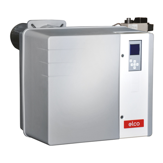
All manuals and user guides at all-guides.com Overview Burner description VG5 M/TC (PED) Control and safety unit Display Air pressure switch F12 Motor thermal protection Motor relay Blower motor Igniter Control panel Y10 Air flap servomotor Adjusting knob for dimension Y Housing Furnace pressure take-off pipe Burner tube... -
Page 5: Operation Operation, Safety Function
All manuals and user guides at all-guides.com Operation Operation Safety function Function description 8 µA. Safety functions - Control thermostat requests heat. - If no flame is produced when the - The control program of the control unit burner is started (gas release), the starts if the air pressure switch contact burner is switched off at the end of the is in the rest position and the gas... -
Page 6: Control And Safety Unit Bt 3Xx
All manuals and user guides at all-guides.com Operation Control and safety unit BT 3xx The control and safety unit BT 3xx Manual locking and unlocking Using the reset button , the control controls and monitors the forced draught and safety unit can be locked manually gas burner. -
Page 7: Terminal Allocation Chart
All manuals and user guides at all-guides.com Operation Terminal allocation chart L1 auxiliary power Flame check supply Ionisation L1 power supply Grounding of Fault Burner motor Flame the burner display UV detector detector Connector 3 2 1 3 2 1 4 3 2 1 Terminal Terminal... - Page 8 All manuals and user guides at all-guides.com Operation Terminal allocation chart Terminal 1 2 3 4 5 6 1 2 3 4 5 6 1 2 3 4 5 6 1 2 3 4 5 6 1 2 3 4 5 6 Connector Fuel oil PC interface...
-
Page 9: Control And Safety Unit Bt 3Xx Gas Operation
All manuals and user guides at all-guides.com Operation Control and safety unit BT 3xx gas operation Boiler safety circuit Gas safety circuit Burner on Minimum gas pressure switch Air pressure switch Flame signal Air flap Gas flap Ignition transformer Gas valve 1 Gas valve 2 Air motor Fault... -
Page 10: Menu Overview Bt 3Xx
All manuals and user guides at all-guides.com Operation BT 3xx menu overview In addition to the function of control and over the burner's entire output Operating values are shown in real time safety unit, the control and safety unit BT modulation range. -
Page 11: Mbc-Se Gas Train
All manuals and user guides at all-guides.com Operation MBC-SE gas train The gas train consists of: - a gas connection flange 1 with O-ring - a gas throttle 2, controlled by a servomotor - a gas connection pipe 3 - an MBC-SE gas valve train with gas filter 4 (mini filter) MBC SE gas valve Electrical connection of solenoid... -
Page 12: Vgd Gas Train With Skp 25 Regulator
All manuals and user guides at all-guides.com Operation VGD gas train with SKP 25 regulator The gas train consists of: - a gas connection flange 1 with O-ring - a gas throttle 2, controlled by a servomotor - a VGD gas valve train with gas filter 4 (mini filter) VGD gas valve Electrical connection of solenoid... -
Page 13: Vgx Mv/Tc Burner
All manuals and user guides at all-guides.com Function VGx MV/TC burner Speed control – VSM100 module Module description VSM100 The VSM100 allows the BurnerTronic to control the speed of the fan motors. The BurnerTronic treats the VSM100 as an additional compound channel. - Page 14 All manuals and user guides at all-guides.com Function VGx MV/TC burner Speed control – VSM100 module Menu description Menu 1: Setting the servomotors, setting without flame Fan activation in the settings menu: for Burnertronic version <3.3.0.0 During operation with the frequency converter, the fan This activation must be motor starts automatically as...
-
Page 15: Air Regulation Acs150 Speed Controller
All manuals and user guides at all-guides.com Function VGx MV/TC burner Air regulation ACS150 speed controller ACS150 manual control panel Overview The following table summarises the key functions and displays of the basic control panel. Art. Use/Function LCD display - Divided into five areas: a. -
Page 16: Assembly Burner Assembly
All manuals and user guides at all-guides.com Installation Burner installation Preparing the boiler front Burner head assembly • Prepare the burner mounting plate/ • Screw the bolts into the burner fixing boiler door in accordance with the plate/boiler door and position the diagram. -
Page 17: Gas Train, Accessories (For Ped Option)
All manuals and user guides at all-guides.com Installation Gas train Accessories (for PED option) Gas train installation • Check the correct position of the O-ring B in the gas connecting flange C. • Secure the gas train with M10 nuts so that the SKP regulator or the coils of the MBC-SE are positioned perpendicular to the gas train. -
Page 18: Checking The Burner Head For Natural Gas And Propane Gas
All manuals and user guides at all-guides.com Installation Checking the burner head for natural gas/propane gas Checking the burner head • Check the adjustment settings of the ionisation probe and of the ignition electrode as per the diagrams. Recommended setting for VG 5.950/1200 M/TC natural gas On the gas diffusers labelled A,... -
Page 19: Burner Head Assembly
All manuals and user guides at all-guides.com Installation Burner head assembly Burner head assembly • Remove the cover (3 screws W). • Check that the O-Ring J1 is in the correct position in the gas bend. • Fit the extension rod with the 0-40 scale (supplied loose in the packaging) for setting the turbulator (see image). -
Page 20: Electrical Connection Checks Before Commissioning
All manuals and user guides at all-guides.com Installation Electrical connection Checks before commissioning General regulations applying to the specified by the draft combustion gas connection ordinance. • The gas train must only be connected It is the responsibility of the fitter or his to the gas mains by a recognised representative to obtain approval for the specialist. -
Page 21: Commissioning Adjustment Values, Measuring The Ionisation Current
All manuals and user guides at all-guides.com Commissioning Adjustment data Ionisation current measurement Frequency Gas pressure Burner output Dimen- Air flap position Gas throttle position Furnace (only MV burners) controller Type of sion Burner pressure setting Full Full Part Full Full mbar Part load... -
Page 22: Air Regulation
All manuals and user guides at all-guides.com Commissioning Air regulation Air regulation - by three pressure regulators (VG5 MV/ TC burners) Combustion air is regulated at two • pressure side, by the gap between points: the baffle plate and the burner tube. •... -
Page 23: Vgx Mv/Tc Burner
All manuals and user guides at all-guides.com Commissioning VGx MV/TC burner Air regulation by ventilation speed ACS150 speed controller Parameter setting mode In Parameters mode, you can: • display and change parameter values • select and change signals, which are displayed in Display mode •... - Page 24 All manuals and user guides at all-guides.com Commissioning VGx MV/TC burner Air regulation by ventilation speed ACS150 speed controller INITIALIZATION DATA INPUT Set the maximum external reference REF1 value Set the minimum value (in percent) corresponding to the minimum signal for AI1 Set the maximum drive output frequency limit Select the motor stop mode MOTOR ROTATION DIRECTION...
-
Page 25: Mbc-Se/Vgd Gas Train Setting
All manuals and user guides at all-guides.com Commissioning MBC-SE/VGD gas valve adjustment Pressure regulator setting MBC-SE gas train setting Pressure regulator setting The gas pressure regulator is set at 10 mbar in the factory. Check the gas pressure after the burner is first started (measuring point at gas train outlet flange) and if necessary, correct gas pressure pBr via adjustment screw S in... -
Page 26: Confirming The "Manual Handshake" Data
All manuals and user guides at all-guides.com Commissioning Confirmation of "Manual Handshake" data The following sequence for confirming or cancelling the data entry is the same for a number of different changes to the parameters. For this reason, this sequence is not illustrated in detail for each of the parameter settings outlined below. The parameter modifications which require a "Manual Handshake"... -
Page 27: Menu 1: Setting The Servomotors
All manuals and user guides at all-guides.com Commissioning Menu 1: setting the servomotors Pre-setting without flame Setting is carried out in 2 phases: Important - Pre-setting without flame At this point, no setting position for the - Setting the flame, to fine tune the servomotors has been defined, settings based on the combustion therefore the burner cannot be started... - Page 28 All manuals and user guides at all-guides.com Commissioning Menu 1: setting the servomotors Pre-setting without flame End of settings menu without flame When all the positions of the servomotors have been determined according to the required settings, it is possible to move on to the next set-up stage, setting with flame. To do this, place the cursor in the lower part of the screen on the symbol and confirm by pressing the...
-
Page 29: Setting With Flame
All manuals and user guides at all-guides.com Commissioning Menu 1: setting the servomotors Setting with flame - If the boiler heating The air flap switches to the request is not present, the ignition/pre-ignition position. burner remains on standby. In this case, it is still possible to return to the previous setting menu "Pre-setting without flame". - Page 30 All manuals and user guides at all-guides.com Commissioning Menu 1: setting the servomotors Setting with flame Setting the ignition position If a flame has been detected, the control and safety unit sets the burner to the ignition position as soon as it receives the regulation authorisation. - Set the fuel controller position and the air flap position according to the desired output level.
-
Page 31: Operating Mode
All manuals and user guides at all-guides.com Commissioning Menu 1: setting the servomotors Setting with flame Operating mode Closing the "Setting with flame" menu The burner setting is now complete. It is still possible, however, to correct the individual values. To do this, position the cursor on the value to be modified, using the key. -
Page 32: Setting The Gas Pressure Switch/Air Pressure Switch
All manuals and user guides at all-guides.com Commissioning Setting the gas pressure switch Setting the air pressure switch Setting the min. gas pressure switch • Turn the dial clockwise until the gas • To set the switch-off pressure: remove pressure switch shuts down the the gas pressure switch cover. -
Page 33: Servicing Maintenance
All manuals and user guides at all-guides.com Servicing Maintenance Replacing the control unit Burner and boiler servicing must only be Work recommended as part of annual - Flame monitor and automatic carried out by a professional heating burner maintenance: combustion control unit function check engineer trained in these operations. - Page 34 All manuals and user guides at all-guides.com Servicing Maintenance Removing the plate • Clean the ventilation turbine and check • Turn off power supply to the motor (4P it is not damaged. connector). • To do this, unscrew but do not remove the 7 screws X securing the motor plate.
- Page 35 All manuals and user guides at all-guides.com Servicing Maintenance Replacing the flame tube Important For this operation, it is necessary to Combustion values must be checked either open the furnace gate or remove under normal operating conditions the burner. (boiler room door closed, hood fitted, - Variant 1 - Access via the furnace gate etc.) after any work is carried out...
-
Page 36: Menu 3: Fault Memory, Entering A Telephone Number For The Maintenance Company And The Maintenance Contract Number
All manuals and user guides at all-guides.com Servicing Menu 3: Fault memory Entering a telephone number for the maintenance company and the maintenance contract number Menu - Fault memory To access the fault memory menu, press any key when the burner is ready for operation or in operation, or when it is in malfunction mode. - Page 37 All manuals and user guides at all-guides.com Servicing Menu 3: Fault memory Entering a telephone number for the maintenance company and the maintenance contract number Continued: Fault diagnosis help signals: Symbol Cause Symbol Cause Symbol Cause Power supply fault Burner safety circuit Air pressure switch malfunction during - min.
-
Page 38: Menu 4: Operating Statistics
All manuals and user guides at all-guides.com Servicing Menu 4: Operating statistics Operating statistics menu To access the operating statistics menu, press any key when the burner is ready for operation or in operation, or when it is in malfunction mode. It is not possible to access the operating statistics menu during the start-up phase. -
Page 39: Setting The Brightness And Contrast Of The Display
All manuals and user guides at all-guides.com Servicing Setting the brightness and contrast of the display This menu offers access to the display contrast and brightness settings. To access the menu, press any key when the burner is ready for operation or in operation, or when it is in malfunction mode. - Page 40 All manuals and user guides at all-guides.com www.elco.net Made in EU. Non contractual document. 06/2016 - Art. Nr. 4200 1041 1103A...
Need help?
Do you have a question about the VG5.950 M/TC and is the answer not in the manual?
Questions and answers